
Grove RT518 Crane Parts Manual – Illustrated Parts Catalog PDF Download
Original price was: $34.95.$19.95Current price is: $19.95.
Complete Grove RT518 (Serial 46326) parts manual in PDF – exploded views, hydraulic schematics, valve banks, cylinders, transmission, engine and every component group indexed for fast part lookup.
Description
Grove RT518 Crane Parts Manual – Illustrated Parts Catalog
This Grove RT518 Crane Parts Manual is the illustrated parts catalog for the RT518 carrier-mounted crane, published by Manitowoc Cranes and dated Jul 31, 2012. It covers the machine by assembly group and lists every part number, description and quantity needed to identify, order and fit replacement components. Instead of searching generic diagrams, you work directly from Grove’s own exploded views and numbered part lists for the RT518.
File Details
- Manual type: Illustrated Parts Manual (Parts Catalog)
- Brand: Grove (Manitowoc Cranes)
- Model: RT518
- Serial number: 46326
- Date: Jul 31, 2012
- Language: English
- Format: PDF (instant download)
- Page count: 715 pages
Chapters & Component Groups Covered
The manual is organized by assembly group so a part can be traced from the complete unit down to the individual fastener. Major groups include:
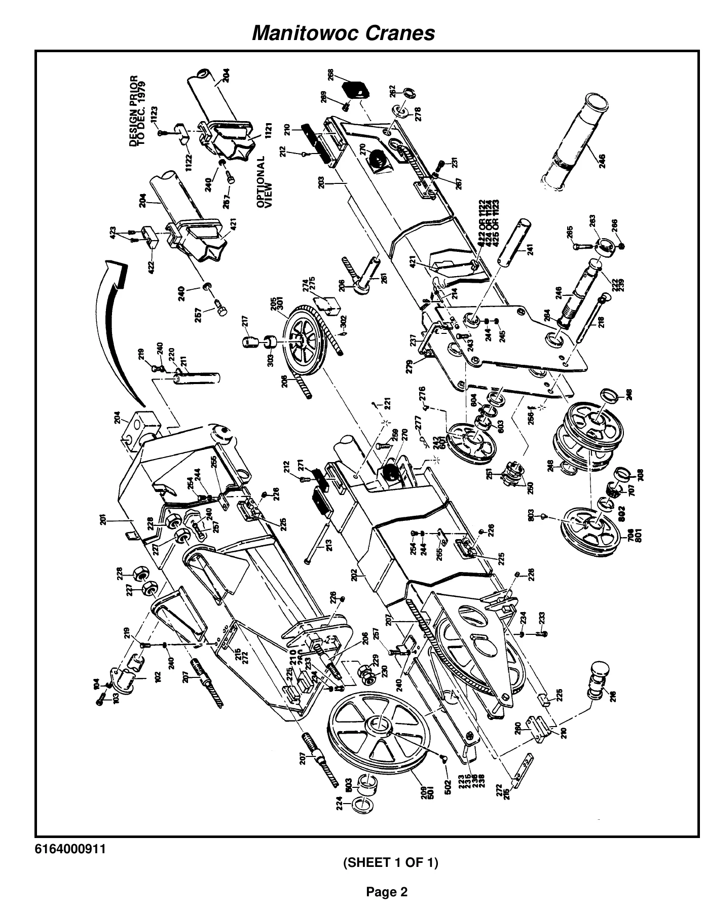
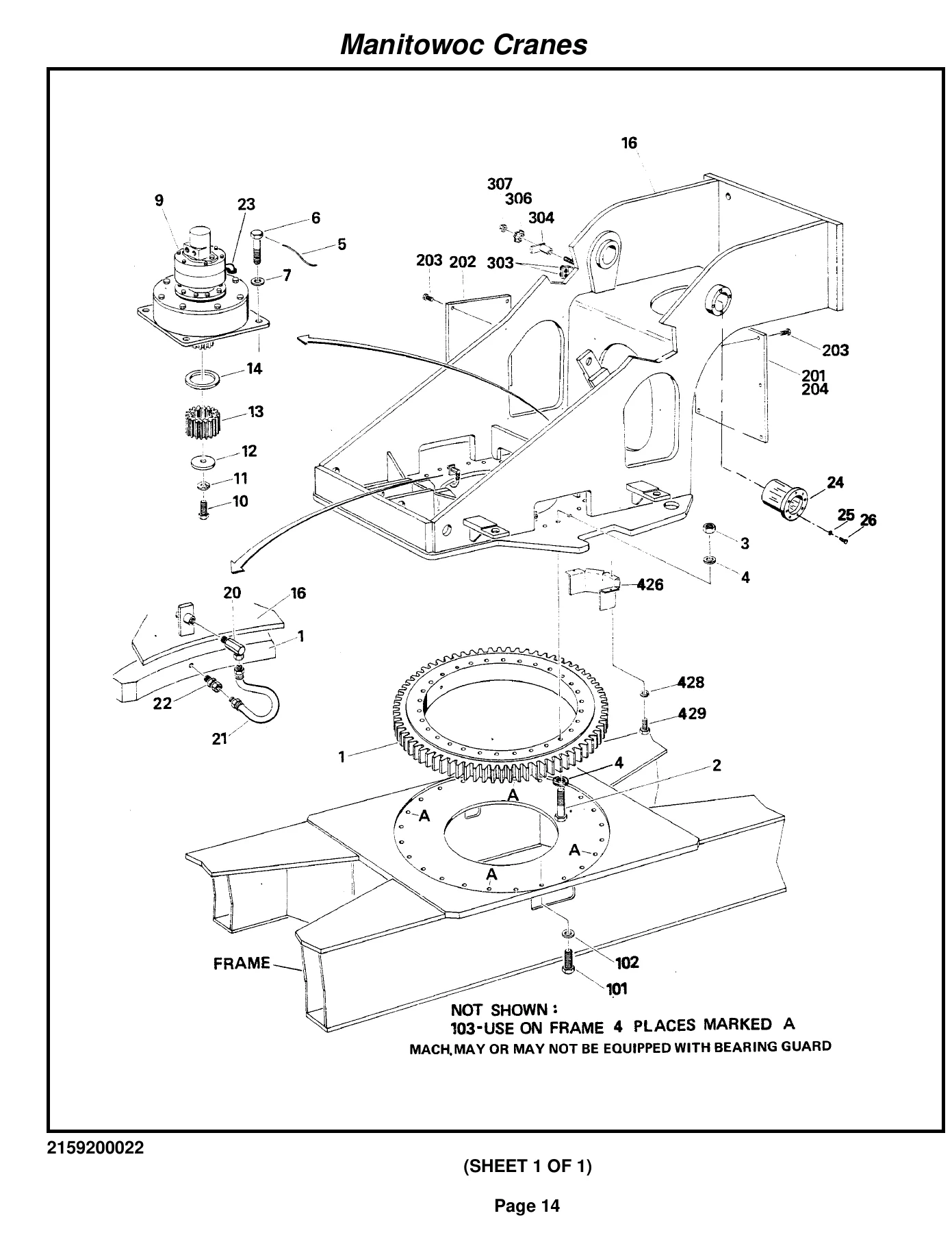
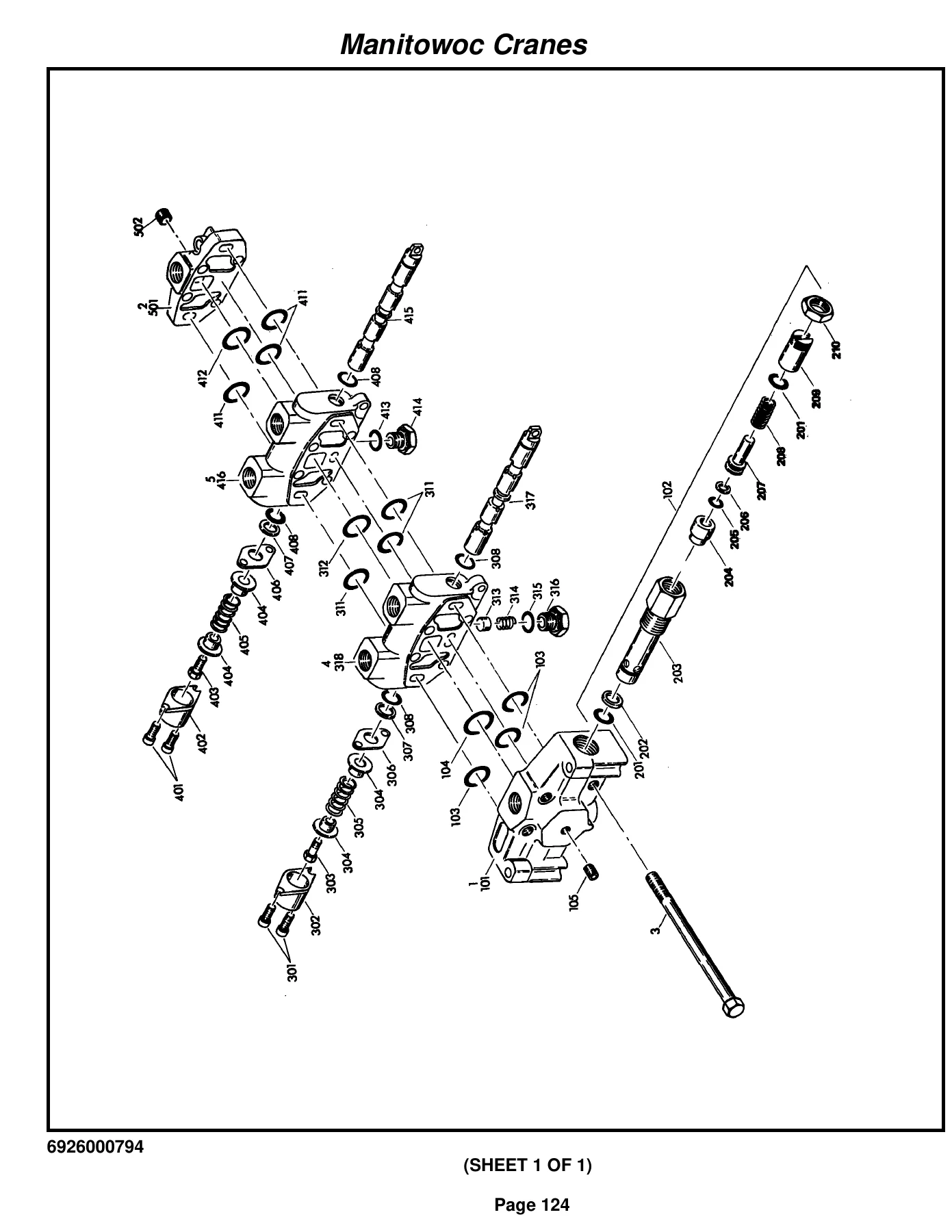
IMAGES PREVIEW
- Boom – 3 section, 28-70 ft cable extended, 3 sheave; complete telescope cylinder assembly
- Boom angle indicator installation
- Hydraulic lines installations (mid telescope, lift, swing, outrigger, front/rear steer, axle lockout, pressure check panel, valve section loop line)
- Superstructure / turntable – drive assembly and bearing installation, bearing bolt installation, cover plate installation
- Swing box – complete assembly, swing box and brake, swing brake assembly, orbit motor assembly, motor control valve assembly, gear reduction
- Counterweight installation
- Lift cylinder installation and cylinder assembly
- Hoist installation – main and/or auxiliary, hoist assembly Model HO15B-16, tubing installation
- Hydraulic motor assembly, swivel assemblies (electric/air/hydraulic), slip ring assembly 36 conductor
- Control valve & linkage – valve bank assemblies (A-35 series, A-20 series), 4-way sections, inlet/outlet sections, relief valves, cartridge assemblies, solenoid assemblies
- Reducing/relief valve installation (swing), pressure and sequence valve
- Rotation indicator – driver assembly, indicator assembly, transmitter assembly
- Solenoid and flow divider valve installations
- Guard installation (pinion), remote cranking pump switch installation, hydraulic test panel installation
- Idler drum and cable follower installation, cable follower, idler drum assembly
- Free swing hydraulic schematic
- Brake valve and air tank installation
- Superstructure cab – cab installation, cab assembly, controls installation
- Pedal and valve assembly (accelerator), control valve assembly
- Dual brake valve assembly, control assembly (without return to center steering)
- Seat assembly, rubber control rod boot
- Transmission shift control valve assembly
- Fire extinguisher assembly and installation
- Instruments and lights installation
- Electrical system installation, fuse and connector panel assembly
- 12-volt cab fan assembly and installation
- Lowerworks / carrier – axle installation, axle assembly (hub and shaft group, differential carrier, housing, brake assembly)
- Steer cylinder assembly (3 in), outrigger beam installation
- Stabilizer cylinder assembly, extension cylinder assembly
- Transmission – installation, assembly, front cover and case, clutch and gear group, axle disconnect, low clutch, forward clutch, reverse and second shift, control valve
- Air lockout cylinder assembly
- Drive line installation and assemblies
- Engine installation – Cummins V-378
- Exhaust and air cleaner installation, air cleaner assembly
- Oil filter assembly, torque converter installation and assembly
- Throttle cylinder assembly, steer pump assembly, pump and disconnect assembly
- Hood installation (engine), hydraulic reservoir installation
- Fuel tank installation, tire and wheel assembly
- Air tank and valve installation, check valve assembly, air-hydraulic actuator assembly
- Transmission and converter lines installation, air system schematic
- Brake lines installation (hydraulic)
- Outrigger valve installation – selector, 4 stack solenoid, sequence, solenoid, relief
- Axle lockout installation, selector valve, lockout cylinder assembly
- Lights installation, battery installation, battery box installation
- Lug nut and washer installation
- Air dryer assembly
- Parking brake installation, spring brake chamber assembly
- Cover installation (front), outrigger pad and storage, float assembly
- Fender installation, back-up alarm installation
- Rear axle lockout valve installation, rear steer indicator installation
- Pintle hook installation and assembly, tie down installation (hook block)
- Engine block heater installation
- Supply, pressure and return lines
- Mirror installation (rear view)
- Decal installation – RT500 Series
Beyond the main groups, the manual also contains an Alphabetical Index, a Numerical Index, a Recommended Spare Parts List, a Belt and Filter Maintenance List, and a Foot Note Index. Taken together, this gives a technician a complete parts identification system for the whole RT518 – from the boom sheaves and telescope cylinder right through to the axle brake shoes, cab hardware, and decals.
What This Parts Manual Gives You
A parts catalog is only useful if it gets you to the right number fast, and this RT518 manual is built for exactly that. Each assembly group has its own exploded illustration with callout numbers keyed to a table of part numbers, descriptions and quantities. That means you can confirm fitment before ordering, avoid returns on costly hydraulic and driveline parts, and understand how a component is assembled before you take it apart.
Because the manual is broken down by system – boom, swing, hoist, valve banks, transmission, axle, cab – you can locate anything from a single O-ring in a valve section to a complete telescope cylinder assembly. Hydraulic schematics such as the free swing diagram and the air system schematic help you trace lines and understand how the circuits interact. The valve bank breakdowns go right down to cartridges, springs, plugs and O-rings, so service kits and individual seals can be identified rather than replacing an entire valve.
Why Technicians Rely on the Correct Grove Parts Numbers
Grove cranes use a very large number of group-specific components, and many of them look similar on the outside. Using the illustrated catalog means you match the part to the exact assembly on your RT518 Serial 46326, including superseded numbers and revision notes that appear throughout the tables. That precision matters most on safety-relevant assemblies – swing brakes, hoist brakes, holding valves, outrigger cylinders and load-holding relief valves – where the wrong seal or spring can cause a failure that is far more expensive than the part itself.
Instant PDF Delivery – No Shipping, Any Device
This Grove RT518 Crane Parts Manual is delivered as an instant PDF download as soon as payment is confirmed. There is nothing to ship and nothing to wait for. You can open it on a laptop in the workshop, a tablet on the machine, or a phone at the parts counter, and print any page you need – whether that is a single exploded view to take under the crane or a full section to keep in the toolroom. The whole 715-page catalog stays in one file, so every assembly group, index and spare parts list is available whenever you need it.
Reviews
There are no reviews yet.