
Grove TMS750B Crane Parts Catalog 2013 – Serial Number 79397 PDF Download
Original price was: $34.95.$22.95Current price is: $22.95.
Complete illustrated parts catalog for the Grove TMS750B crane with serial number 79397. Published August 2013, this 1,205-page PDF covers every major assembly from boom and cylinders to axles, transmission, cab, and hydraulic systems with exploded views and part numbers.
Description
Grove TMS750B Crane Parts Catalog – Serial Number 79397 (August 2013)
This Grove TMS750B Crane Parts Catalog is the comprehensive illustrated parts reference for machines built with serial number 79397. Published August 2, 2013 by Manitowoc Cranes, this PDF gives you exploded-view illustrations and part numbers for every major system on the crane, making it an essential tool for anyone ordering replacement parts, verifying component assemblies, or maintaining a TMS750B in service.
File Details
- Manual Type: Illustrated Parts Catalog
- Brand: Grove (Manitowoc Cranes)
- Model: TMS750B
- Serial Number: 79397
- Publication Date: August 2, 2013
- Language: English
- File Format: PDF
- Page Count: 1,205 pages
Chapters Covered
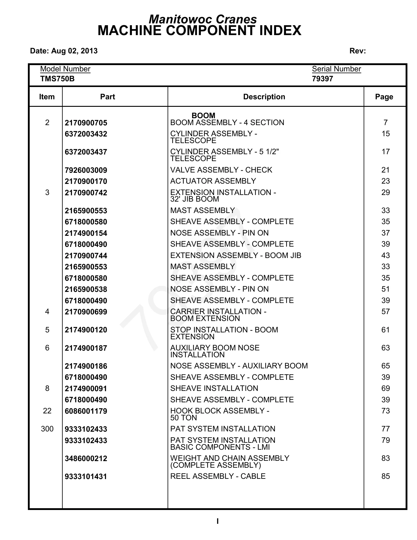
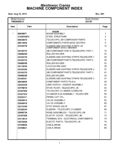
- Boom Assembly – 4 Section
- Cylinder Assembly – Telescope
- Cylinder Assembly – 5 1/2″ Telescope
- Valve Assembly – Check
- Actuator Assembly
- Extension Installation – 32″ Jib Boom
- Mast Assembly
- Sheave Assembly – Complete
- Nose Assembly – Pin On
- Extension Assembly – Boom Jib
- Carrier Installation – Boom Extension
- Stop Installation – Boom Extension
- Auxiliary Boom Nose Installation
- Sheave Installation
- Hook Block Assembly – 50 Ton
- PAT System Installation
- Basic Components – LMI
- Weight and Chain Assembly
- Reel Assembly – Cable
- Roller Guide Assembly
- Console Assembly – DS350G
- Superstructure
- Turntable Drive Installation
- Box Assembly – Swing
- Swing Box and Brake Assembly
- Brake Assembly – Swing
- Motor Assembly – Orbit
- Lower Shaft and Lift Cylinder Installation
- Cylinder Assembly – 10.00″ Lift
- Upper Shaft and Boom Pivot Installation
- Hoist Installation – Main and Auxiliary
- Hoist Assembly
- Group Assembly – Right Hand, Left Hand, Center
- Drum Assembly
- Motor Assembly – Hydraulic Vane Type
- Brake Assembly
- Cable Follower and Idler Drum Assembly
- Counterweight Installation – Removable
- Cylinder Assembly – Lockout
- Swivel Installation – Electric/Hydraulic
- Swivel Assembly – Electric/Air and Hydraulic
- Swivel Assembly – 10 Port
- Ring Assembly – Slip
- Bearing Bolt Installation
- Lock Pin Installation – Turntable
- Manifold Installation – Hydraulic Return
- Valve Installation – Control – Main and Auxiliary
- Valve Bank Assembly – 2 Section
- Valve Assembly – 1 Section Control
- Valve Assembly – Control
- Valve Assembly – Sequence
- Valve Assembly – Pressure Reducing
- Valve Assembly – 5 Station Solenoid
- Valve Cover Installation
- Cooler Installation – Oil Hydraulic
- Motor Assembly – Oil Cooler
- Fan Assembly – Oil Cooler
- Cooler Assembly – Oil
- Cover Installation – Oil Cooler
- Hydraulic Lines Installation – Swing
- Hydraulic Lines Installation – Swing and Swing Brake
- Hydraulic Lines Installation – Lift
- Hydraulic Lines Installation – Main and Auxiliary Hoist
- Hydraulic Schematic – Main and Auxiliary Hoist
- Hydraulic Lines Installation – Telescope
- Hydraulic Lines Installation – Pressure Check Panel
- Air Lines Installation – Cab
- Switch Stowage Installation – Remote CWT
- Control Assembly
- Superstructure Cab Electrical System Installation
- Harness Assembly – S/S
- Electrical System Installation – Cab
- Harness Assembly – Cab Rear
- Cab Installation
- Cab Assembly
- Cab Section
- Door Assembly – Cab
- Window Assembly
- Pedal Assembly – Air Throttle
- Console Installation – Front
- Harness Installation – Front Console S/S
- Harness Assembly – Front Console S/S
- Wiper Installation – Skylight
- Window Assembly – Skylight
- Bottom Cover Installation
- Pedal and Valve Installation – Telescope
- Valve Assembly – Control
- Acoustical Installation
- Pedal Installation – Swing Brake
- Work Light Installation
- Flasher Light Installation
- Light Assembly – Strobe
- Spotlight Installation
- Control Seat Installation – Single Axis
- Control Seat Assembly – Single Axis
- Seat Assembly
- Controller Assembly – Single Axis
- Windshield Washer Installation
- Fan Installation – Cab Circulating
- Fan Assembly – 12 Volt Cab
- Extinguisher Installation – Fire
- Mat Installation – Floor
- Control Handles Installation
- Heater and Defroster Installation
- Heater Assembly – Propane
- Propane Tank and Exhaust Installation
- Kit, Tank Mounting
- Lowerworks/Carrier Frame Assembly
- Suspension Assembly
- Axle/Steering Installation – Front
- Link Assembly – Drag
- Gear Assembly – Power (W/O Return to Center Steering)
- Shaft Assembly – Double U-Joint
- Arm Assembly – Torque
- Torque Arm Assembly
- Axle Assembly
- Wheel and Drum Assembly
- Hub Cap Assembly
- Cylinder Assembly – 2″ Steer
- Axle Installation – Rear
- Axle Assembly – Rear
- Differential Carrier Assembly
- Housing Parts
- Brake Parts
- Beam Assembly – Equalizer
- Drive Line Assembly
- Axle Bearing – Rear
- Adapter Assembly
- Air Lines Installation – Rear Axle
- Fenders and Decking Installation
- Fender Assembly – Left Front, Right Front, Left Rear, Right Rear
- Tray Assembly – Front
- Sling Box Installation
- Cylinder Installation – 5th Outrigger Jack
- Cylinder Assembly – 4 1/2″ Outrigger Jack
- Outrigger Beam Installation
- Cylinder Assembly – Stabilizer
- Cylinder Assembly – 2 1/2″ Outrigger Extension
- Stowage Installation – Outrigger Float
- Float Assembly – Outrigger
- Fuel Tank and Ladder Installation
- Engine Installation
- Transmission Assembly
- Transmission Assembly – Air System
- Transmission Assembly – Main Housing Assembly
- Transmission Assembly – Yokes and Bars Assembly
- Transmission Assembly – Mainshaft – Countershaft
- Transmission Assembly – Main Drive, Idle, Bearing Assembly
- Transmission Assembly – Cylinder Assembly
- Transmission Assembly – Auxiliary Assembly
- Pump Assembly – Steer
- Controller Assembly – Slave Unit
- Cylinder Assembly – Throttle
- Filter Assembly – Fuel
- Harness Assembly – Engine
- Radiator and Air Cooler Installation
- Pump and Manifold Installation
- Pump Assembly
- Drive Assembly – Pump
- Drive Line Assembly
- Coupling Assembly – 2″ Tube
- Coupling Assembly – 1.50″ Tube
- Clutch Control Rod Installation
- Boot, Rubber Control Rod
- Transmission Shift Installation
- Control Assembly – Master Unit
- Cleaner Installation – Air
- Cleaner Assembly – Air
- Exhaust System Installation
- Quick Start Installation
- Battery Installation
- Hood Installation – Engine
- Weatherstrip Installation – Engine Hood
- Exterior Lights and Horn Installation
- Light Assembly – Turnsignal and Marker
- Light Assembly – Left Rear
- Light Assembly – Right Rear
- Light Assembly – Identification
- Alarm Installation – Back-Up
- Mirror Installation – Rear View
- Head and Loop Assembly – Mirror
- Rest Installation – Boom
- Air Tank and Valve Installation
- Dryer Assembly – Air
- Valve Assembly – Spring Brake
- Valve Assembly – Check
- Valve Extension Installation – Tire
- Electrical Systems Installation – Carrier
- Harness Assembly – Carrier
- Harness Assembly – Outrigger
- Reservoir Installation – Hydraulic
- Valve Installation – Control – Outrigger
- Valve Assembly – 5 Stack
- Valve Assembly – 4 Stack Outrigger Solenoid
- Valve Assembly – Integrated Outrigger
- Valve Assembly – Relief
- Hydraulic Lines Installation – Supply, Pressure and Return
- Hydraulic Lines Installation – Outrigger
- Hydraulic Lines Installation – Power Steering
- Valve Assembly
- Valve Assembly – Residual Check
- Cab Installation
- Plenum Assembly – Heater
- Column Assembly – Steering
- Valve Assembly – Dual Brake
- Pedal Assembly – Air Throttle
- Light Assembly – Dome
- Wheel Assembly – Steering
- Seat Assembly
- Fan Assembly – 12 Volt Cab
- Air Lines Installation – Cab
- Door Assembly – Carrier Cab
- Ventilator Assembly
- Console Installation – Front
- Flasher Light Installation
- Light Assembly – Strobe
- Extinguisher Installation – Fire
- Acoustical Installation
- Mat Installation – Floor
- Air Lines Installation – Carrier
- Electrical System Installation
- Harness Assembly – Cab
- Decal Installation – TMS700B
What This Parts Catalog Gives You
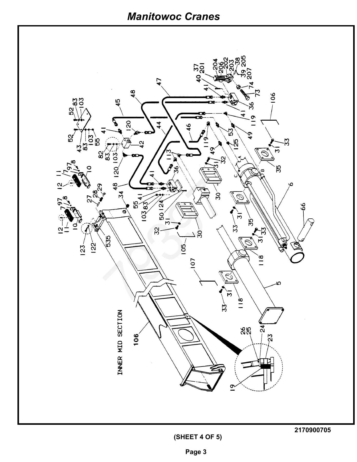
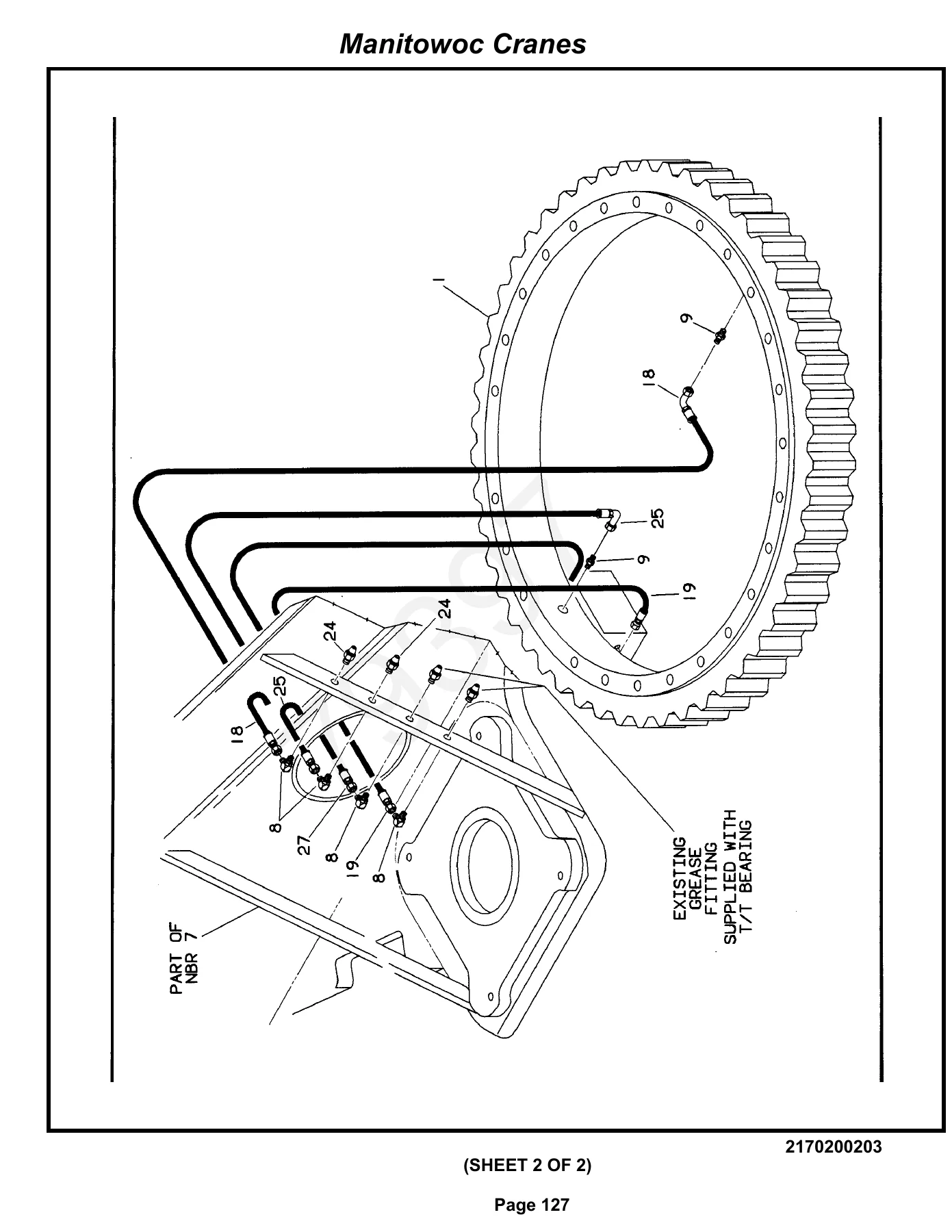
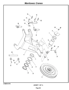
The Grove TMS750B Parts Catalog isn’t just a list of numbers — it’s a complete visual breakdown of how the crane is assembled. Every section opens with an exploded-view illustration that shows how components fit together, with each part tagged by item number that cross-references to a detailed table containing the part number, description, and quantity required. This makes it possible to identify a component visually, confirm you’re ordering the right part, and understand how it interfaces with surrounding assemblies before you ever pick up a wrench.
For a machine as complex as the TMS750B, having the illustrated parts catalog on hand saves hours of guesswork. Whether you’re rebuilding a telescope cylinder, replacing a swing brake, tracking down a hydraulic valve, or simply replacing a worn wear pad, the exploded diagrams and part tables give you the exact reference you need. The catalog covers the entire crane — from the boom sections and jib attachments down through the carrier frame, axles, transmission, engine, outriggers, cab, and all the electrical and hydraulic systems that tie everything together.
Who This PDF Is For
This Grove TMS750B parts manual PDF is built for crane owners, fleet maintenance managers, repair technicians, and parts departments that need fast, accurate part identification. If you maintain a TMS750B with serial number 79397 — or you’re responsible for keeping one running — this catalog eliminates the back-and-forth of trying to describe a broken component over the phone. You can point to the exact item in the diagram, pull the part number from the table, and order with confidence.
Why the Right Parts Reference Matters
Cranes are unforgiving machines. A wrong part number doesn’t just waste money — it can mean a component that doesn’t fit, a system that won’t function correctly, or worse, a safety-critical assembly that fails under load. The Grove TMS750B serial 79397 parts catalog gives you the manufacturer’s own exploded views and part listings, so the part you order is the part that was engineered for your machine. That’s especially important on a crane with multiple design iterations and serial-number-specific configurations, where subtle differences between machines can mean the difference between a direct fit and a costly return.
IMAGES PREVIEW
Instant PDF Delivery — No Waiting, No Shipping
This Grove TMS750B crane parts catalog is delivered as a downloadable PDF immediately after purchase. There’s no physical book to ship, no waiting for delivery, and no shelf space required. The file opens on any device — laptop, tablet, or smartphone — and every page is printable if you prefer a paper copy for the shop or the parts counter. Whether you’re working in the field, at the bench, or at a desk, the catalog is right there when you need it.
Stop guessing at part numbers and start working from the same illustrated reference the professionals use. Get the Grove TMS750B Parts Catalog for serial number 79397 today and have the complete parts breakdown for your crane in your hands in minutes.

Reviews
There are no reviews yet.