
Hamm 3412 & 3520 Tier 3 Electrical Circuit Diagrams Manual – HAMMTRONIC 3412HT to 3625HT Wiring Schematics
Original price was: $59.95.$39.95Current price is: $39.95.
183-page PDF electrical circuit diagram manual for Hamm 3412, 3520, 3412HT, and 3625HT Tier 3 road rollers. Covers CAN-Bus schemas, fuse and relay layouts, EMR-3 and MC6 control devices, Common-Rail diesel engine circuits, lighting systems, sensors, connectors, hydraulic schemas, and spare parts lists.
Description
Hamm 3412 & 3520 Tier 3 Electrical Circuit Diagrams Manual
This comprehensive electrical circuit diagram manual covers the Hamm 3412 and 3520 series road rollers equipped with Tier 3 engines, along with the HT variants spanning 3412HT through 3625HT. The 183-page PDF provides complete wiring schematics, CAN-Bus layouts, fuse and relay assignments, control device pinouts, and hydraulic schemas for these heavy compaction machines. Whether you are diagnosing a fault in the Common-Rail diesel engine circuit, tracing a lighting fault, or verifying a sensor signal, this manual delivers the wiring information needed to get the job done correctly.
File Details
- Manual Type: Electrical Circuit Diagrams / Wiring Schematics
- Brand: HAMM
- Models Covered: 3412, 3520, 3412HT, 3625HT
- Language: English, German
- Page Count: 183 pages
- File Format: PDF
- Document Numbers: 02069545.02, 02108306
- Date: 19.05.2008
- Serial Numbers: Valid from H1760001, H1770001, H1800001
Chapters Covered
- CAN-Bus Schemas
- Fuse Box & Relay Layouts
- Control Devices (EMR-3, MC6)
- Diesel Engine Common-Rail
- Lighting Systems
- Sensors & Switches
- Connectors & Plugs
- Hydraulic Schemas
- Spare Parts Lists
CAN-Bus Schemas
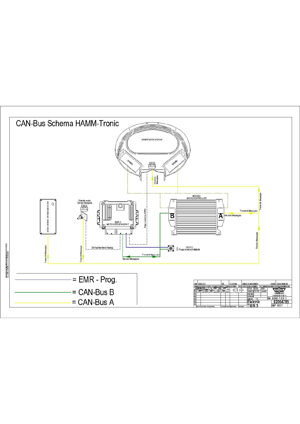
The manual opens with detailed CAN-Bus network schematics for both HAMM-Tronic and Standard configurations. These pages show the communication architecture linking the instrument panel display, engine control unit, and various control modules. The HAMM-Tronic schema includes the EMR-3 motor control unit, the MC6 microcontroller, and the CAN-Bus A and B lines, with transmit and receive message paths clearly marked. This is the starting point for any network communication fault diagnosis on these machines.
Fuse Box, Relay & Power Distribution
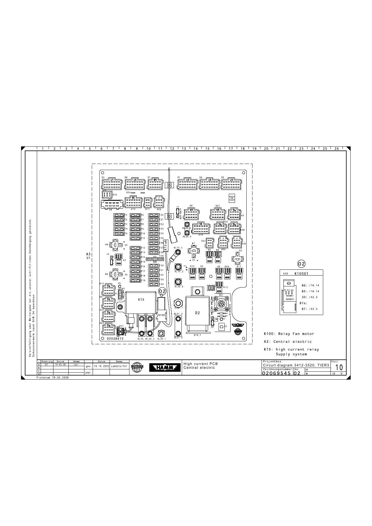
Complete fuse box layouts for the engine room and cab console are provided, with fuse positions, amperage ratings, and the circuits they protect. The high current PCB section details the central electric distribution board, including the K100 relay for the fan motor and the K15 high current relay for the supply system. Relay arrangement diagrams cover the full set of relays from the diesel engine control device and fuel preheating through to the flasher, charge pump, driving lights, parking brake, back-up alarm, blade, starting release, pilot light preheat, and vibration circuits. Power supply schematics show the starting motor, battery, alternator, and battery isolating switch wiring.
Control Devices — EMR-3, MC6 & EDC16
The EMR-3 diesel engine control device is documented across multiple pages with full connector pinouts for the D1X1 and D1X2 plugs, including terminal assignments for sensors, injectors, fuel rail, and diagnostic interfaces. The MC6 microcontroller (Page A and Page B) is covered for the HT series, with power output, sensor input, and switching input connections. The EDC16 variant is also included. These pages are essential for troubleshooting engine management faults, verifying wiring continuity, and understanding the control device signal paths.
Diesel Engine Systems — Common-Rail
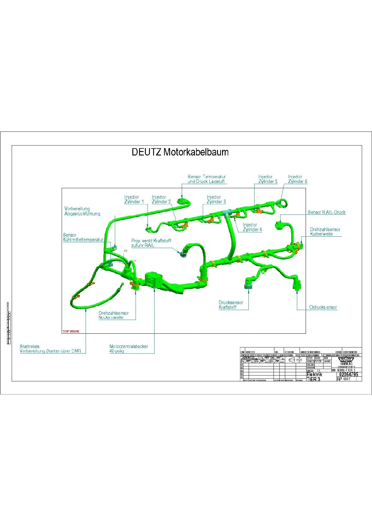
Four dedicated pages cover the Common-Rail diesel engine electrical circuits for both the 3412/3520 and 3412HT/3625HT series. These include the cold start equipment, injection valves for each cylinder, fuel rail valve, pressure sensor fuel rail, fuel low pressure sensor, speed sensors for camshaft and crankshaft, engine oil pressure sensor, charge-air pressure and boost-air thermosensor, coolant temperature sensor, and fuel prefilter sensor. Each circuit is traced from the sensor or actuator back to the control device, with wire colours and connector references.
Sensors, Switches & Operator Controls
Individual circuit diagrams cover coolant level sensors, air filter and hydraulic oil filter pressure switches, inclination sensors, hydraulic oil temperature sensors, padfoot drum switches, speed adjustment potentiometers, fuel level transmitters, refuel pump circuits, fuel preheating, and the drive lever potentiometer. Operator controls including the multifunction handle, parking brake switch, back-up alarm, Schubschild (blade) controls, vibration control, gear shifting, traction control, and steering column switch are all documented with their respective connector pinouts.
Lighting & Cab Systems
Lighting STVZO schematics cover driving lights, parking lights, blinkers, side lamps, working spotlights, rotating-beam lights, and the Lighting ROPS version with its associated connectors. Cab systems include windshield wiper front and rear, cab lighting, door contact switches, radio assembly, instrumentation lighting, tachograph, heating and air conditioning, and the sprinkling system for special equipment. The CDS Display and Compacometer HCM with acceleration sensor are also covered.
Connectors & Plugs
The manual includes an extensive section of connector and plug pinouts for the diesel engine, engine room, front roller, instrument panel, operator platform, cab, air conditioning, heating, sprinkling, and the E-Box. Each connector is shown with its pin numbering and wire assignments, making it straightforward to identify the correct terminal when repairing or replacing harness sections. Central plug layouts for the diesel engine and cab are also provided.
Hydraulic Schemas
Beyond the electrical circuits, this manual also includes hydraulic schematics for the 3412HT, 3414HT, 3516HT through 3620HT, and 3625HT models. These cover the drive and vibration hydraulic circuits, tandem aggregates, variable displacement pumps, planetary axles, travel motors, vibration bearings, and the optional Schubschild (blade) control. Legends with component references are provided for the 3412-3414 and 3516-3520 series, making this a dual-purpose electrical and hydraulic reference document.
Spare Parts Lists
Spare parts lists with component positions, page references, part numbers, descriptions, and machine type applicability are included for fuses, fuse holders, headers, connectors, plugs, sockets, and other electrical components. These lists help identify the correct replacement part for a specific machine serial number range.
Why This Manual Matters
Electrical faults on modern road rollers can be among the most time-consuming and frustrating problems to diagnose without the right documentation. The Hamm 3412 and 3520 Tier 3 electrical circuit diagram manual eliminates the guesswork by providing the complete wiring architecture, component pinouts, fuse and relay assignments, and CAN-Bus communication paths for these machines. Whether you are a workshop technician, a fleet maintenance manager, or an owner-operator performing your own repairs, having the correct schematic in front of you turns hours of wire tracing into a straightforward process.
This manual supports a wide range of jobs: diagnosing a no-start condition through the starting and charging circuits, tracing a fault in the Common-Rail injection system, repairing lighting or wiper circuits, troubleshooting CAN-Bus communication errors between the display and control devices, verifying sensor signals at the EMR-3 or MC6 connectors, and understanding how the hydraulic drive and vibration systems are electrically controlled. The fuse and relay layouts alone are worth the investment, allowing you to quickly identify which circuit is protected by which fuse and which relay controls a given function.
IMAGES PREVIEW
Delivered as an instant PDF download, there is no shipping wait and no physical book to keep track of. The file works on any device — laptop, tablet, or smartphone — and can be printed for use in the workshop. Every page is presented as a clean, legible scan of the original document, with the wiring diagrams, connector views, and component illustrations clearly visible. Whether you need to repair a single circuit or perform a complete electrical system overhaul, this manual gives you the information you need to do the job right the first time.

Reviews
There are no reviews yet.