
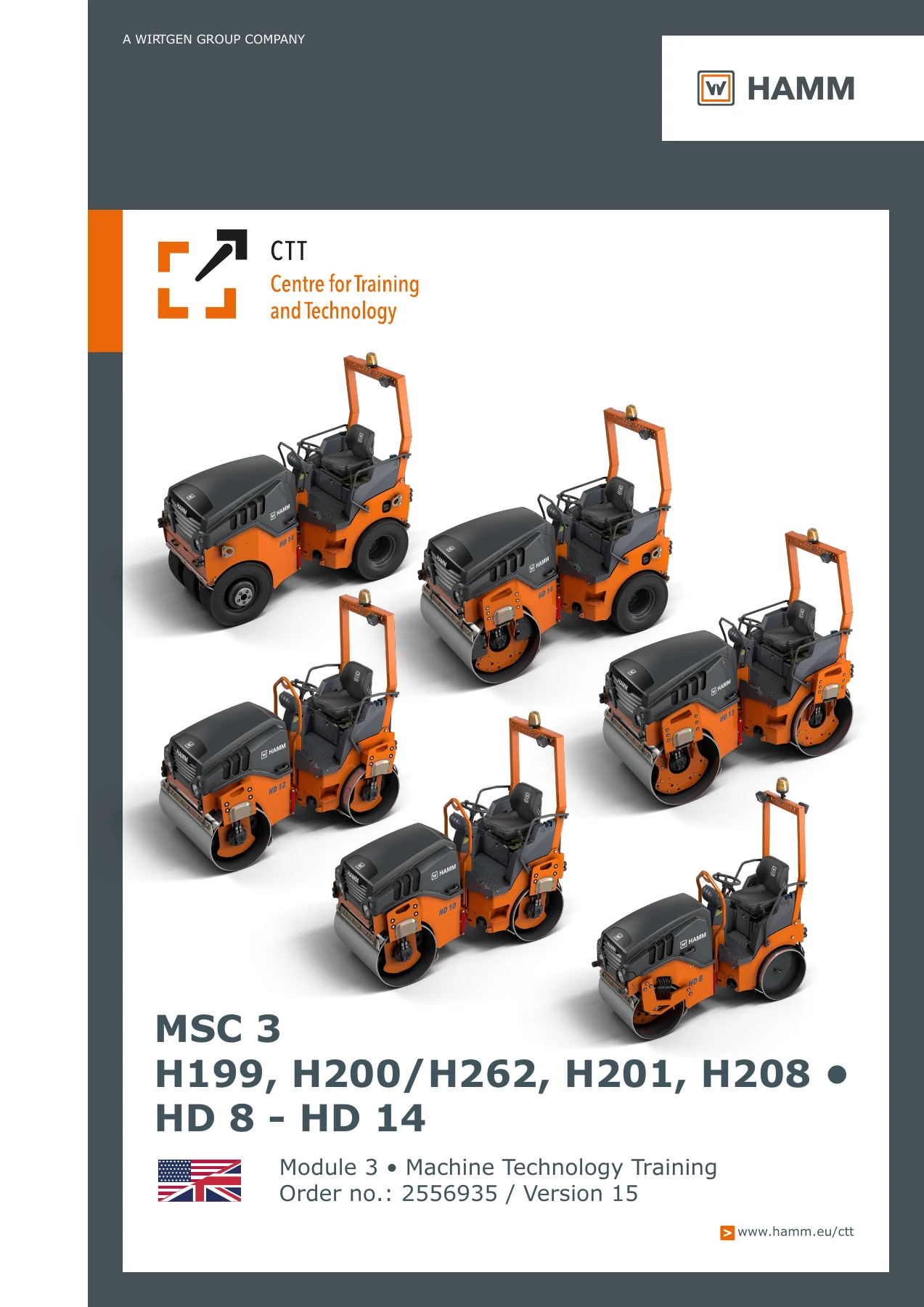
Hamm HD8-HD14 Tandem Roller Machine Technology Training Module 3 Manual – PDF Download
Original price was: $41.95.$27.95Current price is: $27.95.
Hamm HD 8 through HD 14 tandem and combination roller machine technology training manual. Module 3 covers the complete machine: engine, hydraulics, electrical, advance drive, steering, water system, roller drum, edge forming unit and special equipment. 195 pages of detailed technical instruction for H199, H200/H262, H201 and H208 type designations.
Description
Hamm HD8-HD14 Machine Technology Training – Module 3
This Hamm HD8-HD14 Machine Technology Training manual is the complete Module 3 technical training document used to instruct service personnel on the full machine systems of the Hamm HD 8 through HD 14 tandem and combination roller range. Covering the H199, H200/H262, H201 and H208 type designations, this 195-page PDF walks through every major assembly with cutaway illustrations, hydraulic schematics, wiring references and factory technical data tables.
Whether you run an HD 8 VV, HD 10C VV, HD 10 VV, HD 10 VO, HD 10 VT, HD 12 VV, HD 12 VO, HD 12 VT, HD 13 VV, HD 13 VO, HD 13 VT, HD 14 VV, HD 14 VO, HD 14 VT or HD 14 TT, this training manual gives you the system-level understanding that generic operator books never provide. It is the document Hamm technicians study to understand how the machine is built, how each circuit flows, and how the major components interact.
File Details
- Manual Type: Machine Technology Training Manual (Module 3)
- Brand: Hamm (Wirtgen Group)
- Models Covered: HD 8, HD 10C, HD 10, HD 12, HD 13, HD 14
- Type Designations: H199, H200/H262, H201, H208
- Variants: VV, VO, VT, TT
- Language: English
- Page Count: 195
- File Format: PDF
- Order No.: 2556935
- Version: 15
- Publisher: Hamm AG, Tirschenreuth
Chapters Covered
- Machine overview
- Operator’s stand
- Engine
- Fuel system
- Exhaust system
- Cooling engine/hydraulic
- Hydraulics
- Electrical system
- Advance drive
- Steering system
- Water system
- Chip spreader
- Roller drum
- Edge forming unit
- Special equipment
Machine Overview
The opening chapter lays out the complete HD 8 to HD 14 model matrix, breaking down which type designation belongs to which machine and variant. You get the full roller type and model decoding: drum width, Compactline identification, and the meaning behind VV (vibration front and rear), VO (vibration front, oscillation rear), VT (vibration front, tire rear) and TT (tire front and rear). Technical data tables for H199 (from serial number 2091), H200/H262, H201 and H208 give operating weight, static linear load, vibration frequency, amplitude and centrifugal force for every variant. This is where you confirm exactly which machine you are working on before touching a circuit.
Operator’s Stand and Dashboard
The operator’s stand chapter documents the complete dashboard layout, including the operation display, compaction button, traction mode button, and sprinkling/additive sprinkling controls. It covers the lockable dashboard cover for rain and vandalism protection, the warning light panel, and the button functions for vibration big/small, vibration manual/automatic, and the VO-HI-DO pre-selection. The dashboard A1 connector layout is shown, including the thumb wheel setting that must be matched to the machine series and type whenever the dashboard is replaced. Wrong settings are called out for their effect on drive, vibrator and water sprinkling.
Engine
Engine coverage spans the full HD 8 to HD 14 range. The Kubota D1005-E3B three-cylinder engine is documented for HD 8 and HD 10C, the Kubota D1503-M-E3B for HD 10 and HD 12, and the Kubota V2203-M-E3BG four-cylinder for HD 13 and HD 14. All engines meet EU Stage IIIA / EPA Tier 4 (or Tier 4i depending on model). The chapter walks through the engine compartment left and right, identifying the ported vacuum switch, coolant temperature sensor, coolant reservoir, stopping magnet, RPM control lever, fuel pump M4, water separator, fuel filter, engine oil filter, hydraulic oil tank, fuel pre-filter and hydraulic oil filter HV1. Starter relay K01, battery G1, main fuse 80A, battery isolation switch Q1, alternator G2 and starter M1 are all located and described.
Fuel, Exhaust and Cooling Systems
The fuel system chapter documents the suction/pressure line routing, filter unit, fuel level sensor B9, return line and tank. The fuel level sensor is detailed with its float positions for 2/3, 1/3 and 1/10 tank levels. Refuelling notes explain that on HD10VV to HD14VV the fuel cap is under the open bonnet, not externally visible. The exhaust system chapter covers the silencer, exhaust gas hose and flue gas pipe. The cooling chapter breaks down cooling air, heat exchange and air outlet, with the air filter, air filter cartridge, safety cartridge, pressure switch S8, intake hose and dust discharge valve.
Hydraulics
This is one of the most detailed chapters in the manual. It documents the hydraulic oil tank HX100, valve parking brake HQ1, suction filter HV10, breather HV100, and the special wrench for the breather filter. The drive pump HG1 is covered port by port: working connections A and B, leak oil connection T1, mechanical stroke limitation, emergency stop valve HQ7 connection, feed pressure, venting and end stop. The emergency stop valve HQ7 block is shown with its solenoid valve and control block. The distributor block HX1 is documented in VV, VO and VT versions with all working, leakage and measuring connections. The valve block HA10 for vibration switching is shown in both VV and VT versions. Vibration motor HM10 and HM11, brake control block HQ1, and the control block for all-wheel lock are all detailed with their connection ports and functions.
Electrical System
The electrical chapter opens with the central electrical box, showing the glow timer K02, permanent positive X30 and ignition plus X15. The fuse and relay assignment is fully tabulated: K1 through K11 relay functions and F1 through F17 fuse assignments, including all-wheel lock, timer, drum light, driving lights, back-up light, working spotlights, edge pressing assembly, foot whisper water, seat heating, plug socket, signal horn, additive pump, water pump and rotating-beacon light. The display A1 is shown from the rear with all connector positions X1 through X8 plus X30 and X15. The battery, battery isolating switch Q1 and main fuse W1 are located. The time relay with its 1-15 minute adjustable delay is documented with function diagram.
Advance Drive and Steering
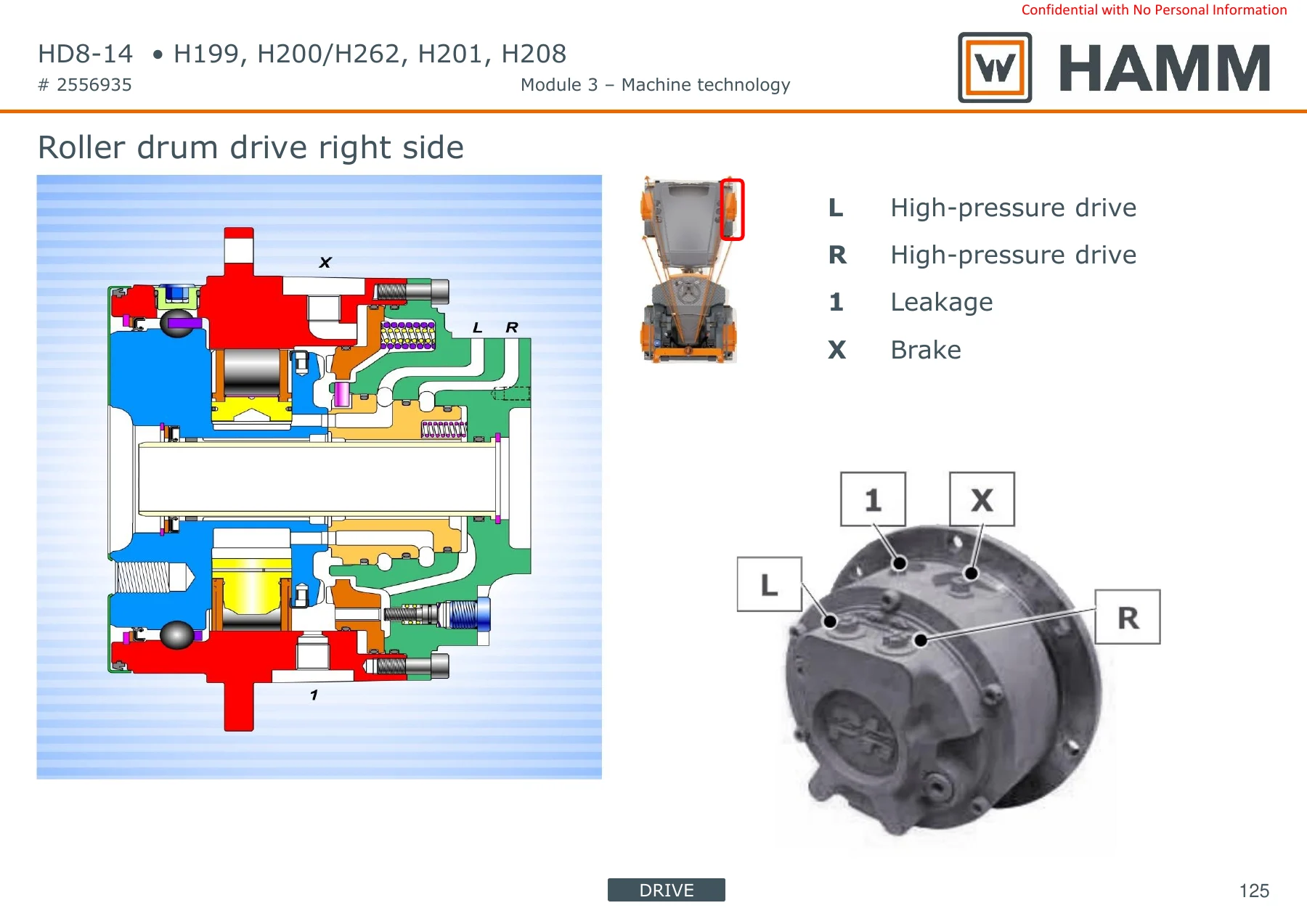
The advance drive chapter covers the high-pressure drive L and R, leakage vibration, and high-pressure vibration A and B for both the HD 8-10C and HD 10-12 arrangements. The roller drum drive right side is shown in cutaway with all connections. Advance drive routing diagrams are provided for Version VV/VO and Version VT, plus a dedicated HD 14 TT diagram. The parking brake circuit is shown for both VV/VO and VT versions. The steering system chapter documents the steering unit HQ20 with mounting plate HX20, steering pump HG20, valve block parking brake HQ1, distributor block HX1 and steering cylinder HM20. The Orbitrol is diagrammed, and the 3-point articulation is explained with its benefits: equal weight distribution, drive stability, enhanced directional stability, and no roll in the asphalt by cornering. The 50 mm permanent drum offset adjustment is covered.
Water System, Chip Spreader and Roller Drum
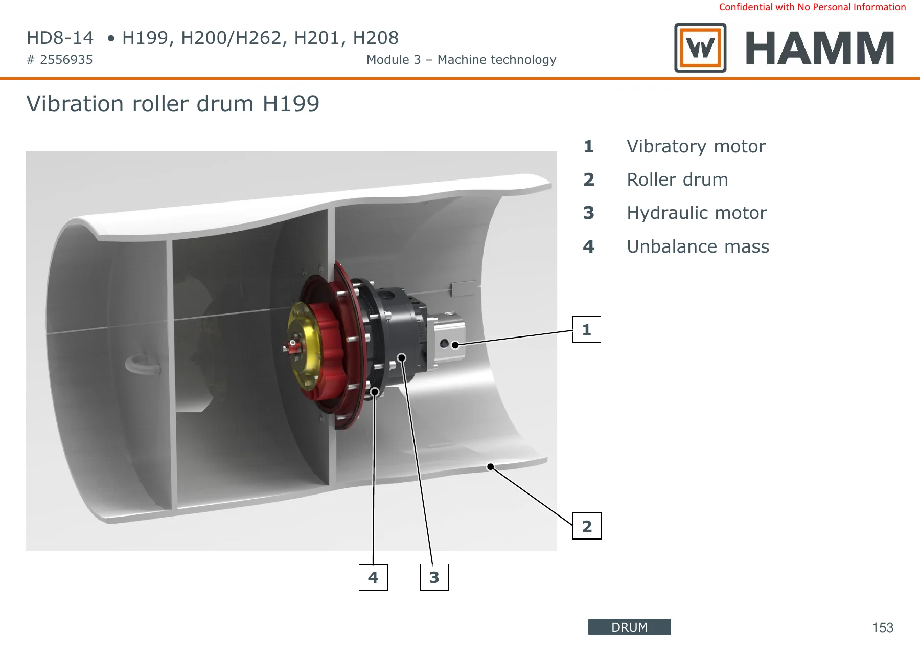
The water system chapter covers the sprinkling overview, interval timing tables for HD 8/10C, HD 10/12 and HD 13/14, and the pump room with water drainage. The water pump M2 is detailed with suction line, pressure line, power supply and mass connections. Spray nozzle counts are given per model. The additive tank for T-Version machines is shown, along with the sprinkling edge pressing and cutting assembly switchable option for HD 10 to HD 14. The chip spreader chapter documents the operating unit and valve block. The roller drum chapter is where the vibration and oscillation systems are fully explained: the vibration roller drum H199 cutaway, the unbalance mass, imbalance wave, bearing flange, tension pulley, toothed belt and toothed wheel arrangement. The vibration motor HM10/HM11 connections are shown, and the complete vibration/oscillation connection overview is provided.
Edge Forming Unit and Special Equipment
The edge forming unit (KAG) chapter documents the cutting wheel and pressure roller configurations with 45° and 60° angles in 3 cm and 5 cm sizes. The water sprinkling for the edge forming unit is covered with the stop cock, solenoid valve, spray nozzle and on/off switch. The special equipment chapter covers the full options list: track indicator, thermal apron, canopy, antifreeze injection for water sprinkling, working lights in halogen or LED, road traffic act lighting, drum lighting LED, rotary beacon, back-up alarm, battery isolating switch, WIFMS interface, bio hydraulic oil, fire extinguisher, rearview mirror, licence plate bracket, V-belt protection, foldable ROPS, cabin for HD 13 and HD 14, and all-wheel lock. The HMV compaction meter and Hamm temperature meter options are documented with their display indicators.
Why This Hamm HD8-HD14 Training Manual Matters
This is not a generic operator’s booklet. It is the Module 3 machine technology training document that Hamm uses to bring technicians up to speed on the complete HD 8 to HD 14 platform. Every major system is opened up: the hydraulic schematics show you exactly which port feeds which motor, the electrical tables tell you which relay and fuse protects which circuit, and the engine chapters give you the component locations and technical data you need before you start diagnostics.
If you are servicing, repairing or diagnosing an HD 8 VV, HD 10C VV, HD 10 VV, HD 10 VO, HD 10 VT, HD 12 VV, HD 12 VO, HD 12 VT, HD 13 VV, HD 13 VO, HD 13 VT, HD 14 VV, HD 14 VO, HD 14 VT or HD 14 TT, this manual gives you the system knowledge to work correctly rather than by guesswork. The vibration and oscillation circuits alone are worth the price of admission: the cutaways show the unbalance mass arrangement, the belt drive, the bearing flanges and the hydraulic motor connections that you cannot see with the drum assembled.
Technical data tables are included for every type designation, so you can confirm operating weight, static linear load, vibration frequency, amplitude and centrifugal force before you adjust or repair. The dashboard replacement procedure with the thumb wheel setting is a classic example of a job that goes wrong without the right documentation: fit a dashboard with the wrong setting and the drive, vibrator and water sprinkling all behave incorrectly. This manual tells you the correct values for each machine.
IMAGES PREVIEW
Instant PDF Delivery
The manual is delivered as a PDF download immediately after payment. No shipping, no waiting for a physical book, no customs delays. You can open it on any device — laptop, tablet or phone — and print the pages you need for the workshop. The 195-page file is organised by chapter so you can jump straight to the system you are working on: engine, hydraulics, electrical, advance drive, steering, water system, roller drum, edge forming unit or special equipment.
Whether you are a fleet owner maintaining your own Hamm rollers, an independent technician taking on your first HD series job, or a training centre building a reference library, this Hamm HD8-HD14 Machine Technology Training Module 3 manual gives you the complete machine-level understanding that the factory expects its own service network to have.
Reviews
There are no reviews yet.