

Hartzell Propeller Aluminum Blade Overhaul Manual 133C Rev 50 Jan 2026
Original price was: $42.95.$24.95Current price is: $24.95.
Hartzell Propeller LLC Manual 133C (61-13-33) Revision 50, January 2026. Inspection, repair, and overhaul procedures for forged aluminum propeller blades used in compact, lightweight, and steel-hub assemblies, including shank work, airfoil limits, travelers, and blade/tip specification tables.
Description
Hartzell Propeller Aluminum Blade Overhaul Manual 133C Rev 50 Jan 2026
The Hartzell Propeller Aluminum Blade Overhaul Manual 133C Rev 50 Jan 2026 is the component overhaul text used when a Hartzell aluminum propeller blade is taken apart, inspected, repaired, refinished, and returned to service. Hartzell Propeller LLC published it as Manual No. 133C, ATA 61-13-33. Revision 50 is dated January 2026. The document states it has been reviewed and accepted by the FAA and contains data approved in a manner acceptable to the FAA Administrator. It is written for propeller repair-station personnel who already have training, tooling, and the companion Hartzell publications it cites. It is not a complete self-teaching course for an inexperienced technician working without supervision.
Aluminum blades in this book are forged and heat-treated from a single piece of aluminum. They appear in both steel-hub and aluminum-hub propellers and are identified by shank design, basic design diameter, tip shape, and suffix letters for shot peening, boots, hard alloy, Q-tips, and related features. The blade model is impression-stamped on the butt and may also be ink-stamped or labeled on the camber side. A typical propeller identity is written as propeller model / blade model. Experimental parts marked with an “X” near the model or part number are not for type-certificated aircraft. Composite blades are outside the scope of this manual; the text points those jobs to Composite Blade Overhaul Manual 135F (61-13-35).
File Details
- Manual type: Aluminum blade overhaul manual
- Brand / publisher: Hartzell Propeller LLC
- Document: Manual No. 133C, ATA 61-13-33
- Revision / date: Revision 50, January 2026
- Language: English
- Page count: 752
- File format: PDF
Who This Manual Is For
Personnel performing the work are expected to hold the equipment, training, and certifications required by the applicable aviation authority. Maintenance records must follow FAA or equivalent rules, including 14 CFR Part 43. The sequence of work is not locked to the chapter order. A traveler in Appendix B suggests a practical path, but shop conditions and blade condition can change the order. Every applicable step still has to be completed. Calendar time between overhauls is specified in Hartzell Service Letter HC-SL-61-61Y, not inside this book. Hours and calendar limits both matter. TSN never returns to zero; TSO returns to zero only after a full overhaul.
Revision 50 is a minor revision that updates front matter, revises Table 2-10 Counterweight Mounting Hardware, removes the former Table 2-12 counterweight slug torque table, and adds the entire Fits and Clearances chapter. Service documents already incorporated include selected Service Bulletins, Service Letters, and Service Advisory SA75. Active service literature can still supersede a printed page, so the reader is told to check current Hartzell indexes.
Chapters Covered
- Introduction — purpose, referenced publications, personnel, tooling and consumables, chemical handling, calendar limits and storage, component life and overhaul, damage types, propeller critical parts, warranty, definitions, abbreviations, dimensions
- Description and Operation — overview of aluminum blades; propeller and blade model designation; blade shank specifications for Y, D, E, X, V, MV, W, Z, M, P, R, and T shanks
- Blade Shank Overhaul — special inspections pointer; single-shoulder and double-shoulder cleaning, inspection, and repair; pitch change knob; pitch change bracket holes; balance hole; blade bore; shank conversions (X to V, Z to W, P to R); counterweights and counterweight knobs
- Blade Airfoil Overhaul — station setup; straightening; grinding and polishing; chemical etch and penetrant; eddy current; thickness, width, length, angle, twist, face and edge alignment; length reduction; shot peen repair; Q-tip blades; lightning strikes; anodizing; optional AT-802 and AN-38-100 conversions
- Special Inspections and Procedures — hard-alloy overhaul, eddy current, anodize and straighten; application-specific checks and retirements (including selected HC-B3TN-5, HC-B4TN-5, HC-12X20, Dornier DO-228 LT10574, Shorts SD3-60, and compact Y-shank serial groups)
- Finish — painting; Teflon tape on D, E, and Y shanks; hard coating on shank radius; split bearing race and retaining ring; blade-bore lubricant
- De-Ice Boot — boot work relocated to Ice Protection System Manual 180 (30-61-80)
- Blade Balancing — static horizontal and vertical balance of blade sets
- Fits and Clearances — torque values for counterweight and slug hardware (Table 8-1) and torque-wrench adapter calculation
- Illustrated Parts List — exploded views and parts lists for each shank family, plus miscellaneous blade parts; O/H column identifies parts replaced at overhaul
- Appendix A — Optical Comparator — overlay inspection of the retention radius after repair
- Appendix B — Travelers — step lists for D/E/Y, M/P/R/T/W/Z, MV, and X/V shanks plus dimensional travelers
- Appendix C — Blade/Tip Specification Tables — station-by-station width, thickness, face alignment, and tip-shape data for aluminum blade series from early compact designs through later T- and M-shank families
- Appendix D — Rolling Machine — DT-1724-3( ) and DT-1724-5 setup, recipes, and rolling of single-shoulder retention radii
Taken together, the Hartzell Propeller Aluminum Blade Overhaul Manual 133C Rev 50 Jan 2026 gives a repair station the inspection limits, repair methods, travelers, parts identity, and dimensional tables needed to overhaul a Hartzell aluminum blade rather than a complete propeller hub assembly. Companion books still required for many shops include Standard Practices Manual 202A (61-01-02) for anodize, penetrant, paint, packaging, and NDT; Illustrated Tool and Equipment Manual 165A (61-00-65); Ice Protection System Manual 180; Application Guide 159; and rolling-machine manuals 128 and 178.
Shank Families and Model Identity
Table 1-2 groups aluminum shanks by hub type, retention, internal bearing, and pitch-change hardware. Compact aluminum hubs use the Y-shank with a single shoulder, one needle bearing, and an integral pitch-change knob. Lightweight aluminum hubs use D- and E-shanks with a bolt-on pitch-change bracket. Steel hubs use X and V (double shoulder), plus single-shoulder MV, W, Z, M, P, R, and T designs with blade bushings and/or needle bearings and various clamp or pitch-change parts (C-3, D-6831, C-1301, C-1977 families).
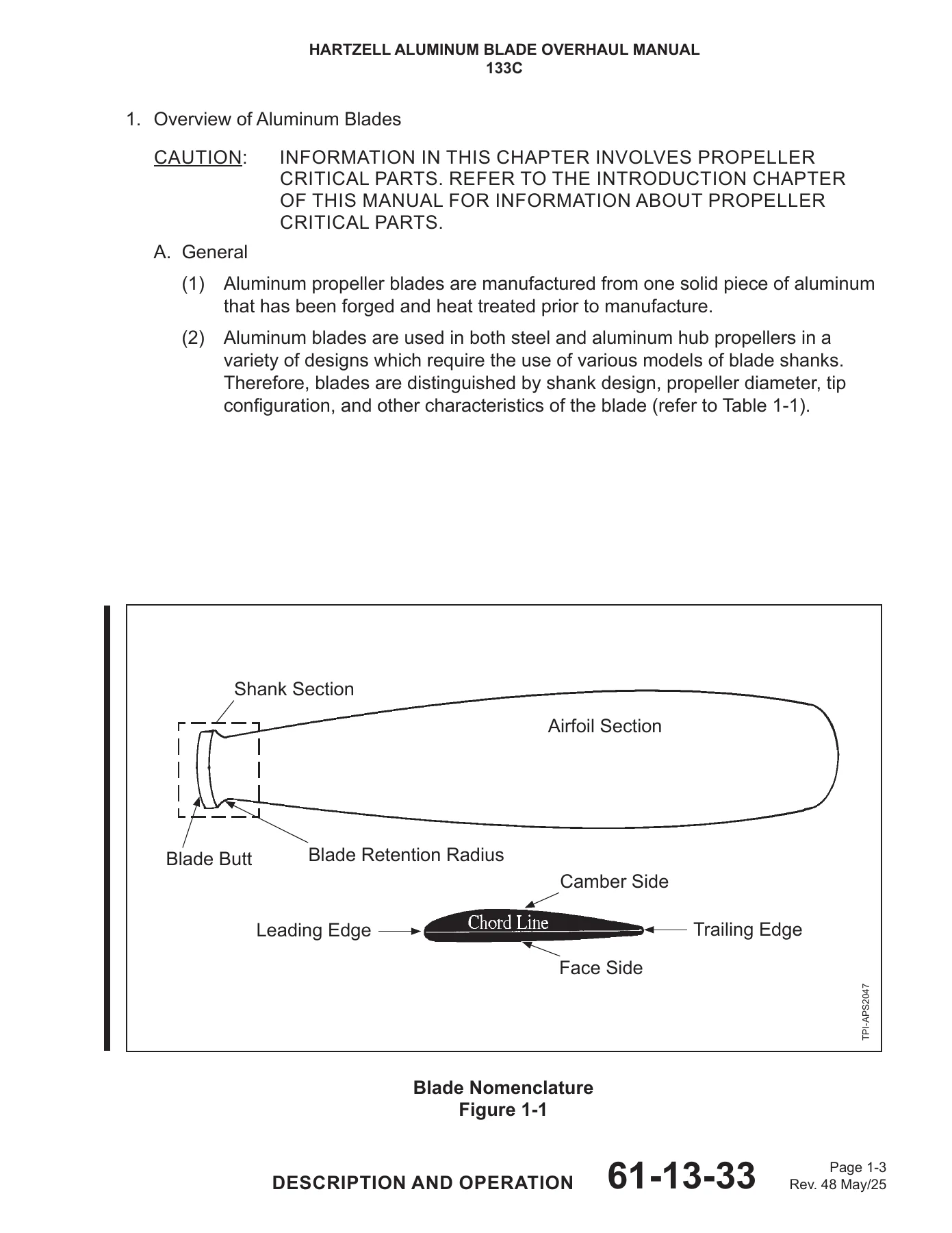
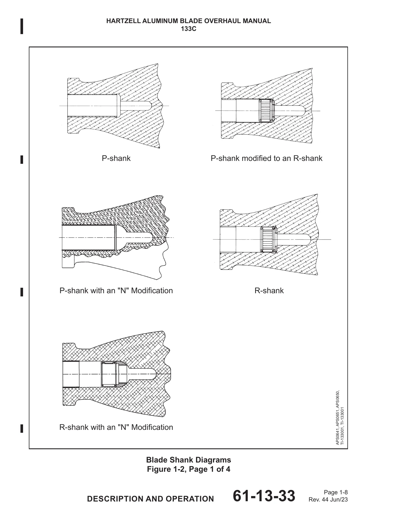
Prefix letters in the blade model usually name the shank (T10282 is a T-shank). Y-shank blades are an exception and do not carry a “Y” in the model string. A dash or plus number is a diameter change from the basic design; T10173-8 is eight inches shorter than the basic 10173 design. Suffix letters flag dimensional changes, boots (B, K, E), hard alloy (H), shank “N” modification, Q-tips, rounded or square tips, shot peening (S), and twist. An asterisk-number after the model points to a paint, de-ice, or counterweight difference on that individual configuration. Figure 1-1 names shank section, airfoil, blade butt, retention radius, camber, face, chord, leading edge, and trailing edge. Figure 1-2 draws P, R, M, T, Y, D/E, Z, W, X, V, and MV bores, including “N” modifications.
Shank Work That Occupies Most of the Book
Single-shoulder and double-shoulder chapters walk through plastic-media or solvent cleaning, outside-diameter and height measurements, retention-radius finish, optical-comparator overlay checks, penetrant inspection at least 4.0 inches (102 mm) outboard of the butt, compression rolling, chemical conversion coating, and the anodize-to-conversion-coat transition. Example limits printed in the shank chapter include a 3.334 inch rolled diameter requirement on applicable D, E, and later Y-shanks, a 4.187 inch (106.35 mm) OD check on several steel-hub shanks, and F-knob diameter limits of 0.621 inch (15.78 mm) small and 0.800 inch (20.32 mm) large. “F” knobs on Y-shanks must be shot-peened at the next overhaul if not previously done, and at every overhaul on aerobatic and agricultural applications.
Blade-bore work covers critical-area diameter and depth, tapered “X” area repairs on T and M shanks, bushing press-fit with gasket sealant CM46 on P and Z shanks, and internal needle-bearing installation. Conversion of X-shank to V-shank is mandatory at overhaul. Z-to-W and P-to-R conversions are also written out, with a caution not to convert a Z-shank that already has an “N” modification to a W-shank. Counterweight chapters cover matched and unmatched weights, dowel-pin holes, thin-wall and B-6143 staked inserts, and repair of oversized 7/16-20 UNF-3B and 1/2-20 UNF-3B tapped holes. Fits and Clearances Table 8-1 lists counterweight torques such as 65 Ft-Lb (89 N·m) for A-3208 and B-3850-12 7/16-20 12-point bolts, 70 Ft-Lb (95 N·m) for B-3826 1/2-20 bolts, and slug hardware from 10 Ft-Lb (13.6 N·m) to 36 Ft-Lb (48.8 N·m). Torque tolerance is ±10 percent unless noted; values are for non-lubricated threads unless the table says otherwise.
Airfoil Limits, Shot Peen, and Application Notes
Airfoil overhaul starts by locating the 0-inch station from the blade butt. That offset changes with shank type; compact Y-shanks commonly use 1.000 inch, while many steel-hub T and M blades use 4.512 inches and several V/X/MV families use 4.150 inches. Technicians then straighten within published bend limits, grind and polish without cutting into the concentric shank, etch, penetrant-inspect the airfoil from the tip to about 4.00 inches (101 mm) outboard of the retention radius, and measure thickness, width, length, angle, twist, face alignment, and edge alignment against Appendix C. Width and thickness minima in those tables are absolute. There is no separate in-service versus overhaul limit: if a station is below the published minimum, the blade is retired.
IMAGES PREVIEW
Length reduction is tightly controlled. Shortening a blade that was bent beyond limits solely because the new tip would sit inboard of the bend is no longer permitted. Shot-peened blades carry an “S” after the model and visible pebble grain. Re-peening, local repair inside the peen zone, and adding peen to selected non-peened models in Table 3-9 are covered. Q-tip blades are factory-bent 90 degrees toward the face; field forming of a new Q-tip is not permitted, though a slightly deformed tip up to 20 degrees may be repaired and Figure 3-10 gives tip thickness. Lightning-strike arcing up to 0.125 inch (3.18 mm) diameter may be blended, polished, and penetrant-inspected; larger heat-affected areas require retirement or factory evaluation plus a Brinell check.
Anodize is required at overhaul on the airfoil but is not permitted in the shank region or the blade bore. Hard-alloy blades have extra eddy-current, anodize, and interchange rules in Chapter 4. Application-specific items include Dornier DO-228 LT10574(A)(S)(B) conversion to LT10574F(N)(S)(B), retirement of certain non-“F” 8475-( ) and 8477-( ) blades over 1000 hours, additional shank wall checks on T9212, 10172, 10173, and 10176 families, and optional M11276N to M11276NA marking for AT-802( ) Air Tractor work that changes RPM limits.
Finish, Balance, Parts, and Shop Tools
Polished-only operation is not permitted. Corrosion protection and an approved paint scheme from Manual 202A must be maintained. D, E, and Y shanks receive Teflon tape CM155 or CM156 on the hub-seal land so the O-ring or quad ring does not wear the shank. Other shanks receive sealer CM49 on the radius. Split bearing races on D, E, and Y blades are matched by serial number. Static balance is done horizontally and, for two-blade sets, vertically on a stand with the correct shank adapter; lead wool in the balance hole is the usual correction.
The illustrated parts list is organized by shank, with an O/H column that marks parts replaced at overhaul. Appendix A uses optical comparator TE28 and overlay TE18-( ) to confirm retention-radius shape after metal removal. Appendix D covers the DT-1724-3( ) rolling machine (PLC recipes by shank) and related DT-1724-5 equipment used to cold-work the single-shoulder retention radius on C, D, E, M, MV, P, R, T, W, Y, and Z aluminum blades.
Start Work With Current Data
The Hartzell Propeller Aluminum Blade Overhaul Manual 133C Rev 50 Jan 2026 supports the jobs a propeller shop actually bills: shank OD and height checks, retention-radius rolling and overlay inspection, pitch-change knob and bracket repair, bore and bushing work, mandatory X-to-V conversion, counterweight hardware torque, airfoil grind and dimensional restore to Appendix C tables, shot-peen restore, Q-tip and lightning-strike evaluation, hard-alloy extra inspections, finish and tape, and static balance of a blade set. Those procedures only stay valid when the technician uses the current revision, the matching traveler, and the latest service documents. Incorrect finish on the retention radius, anodize in the bore, mixed “N” and non-“N” blades where mixing is forbidden, or a station below minimum width or thickness can take a blade out of type design.
Download the PDF after purchase. There is no printed shipment. Open it on a shop computer, tablet, or phone and print the traveler, specification table, or parts figure you need for the blade on the bench.
Reviews
There are no reviews yet.