Haulotte Forklift SIGMA 16 – SIGMA 46 Maintenance Manual PDF
$24.95
Haulotte Forklift SIGMA 16 – SIGMA 46 Maintenance Manual – PDF DOWNLOAD
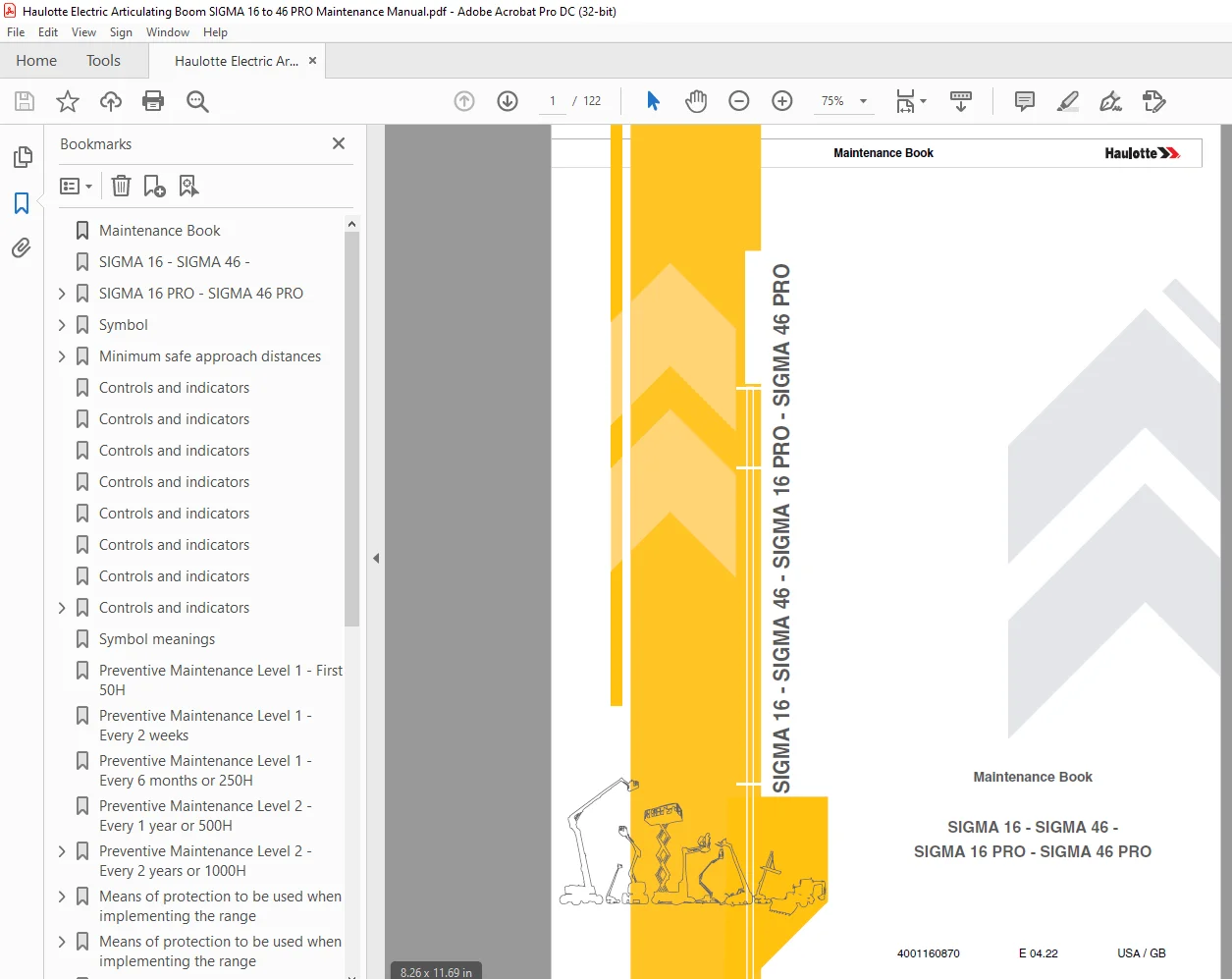
SIGMA 16 – SIGMA 46 –
SIGMA 16 PRO – SIGMA 46 PRO
Description
Haulotte Forklift SIGMA 16 – SIGMA 46 Maintenance Manual – PDF DOWNLOAD
FILE DETAILS:
Haulotte Forklift SIGMA 16 – SIGMA 46 Maintenance Manual – PDF DOWNLOAD
Language : English
Pages :122
Downloadable : Yes
File Type : PDF
SIGMA 16 – SIGMA 46 –
SIGMA 16 PRO – SIGMA 46 PRO
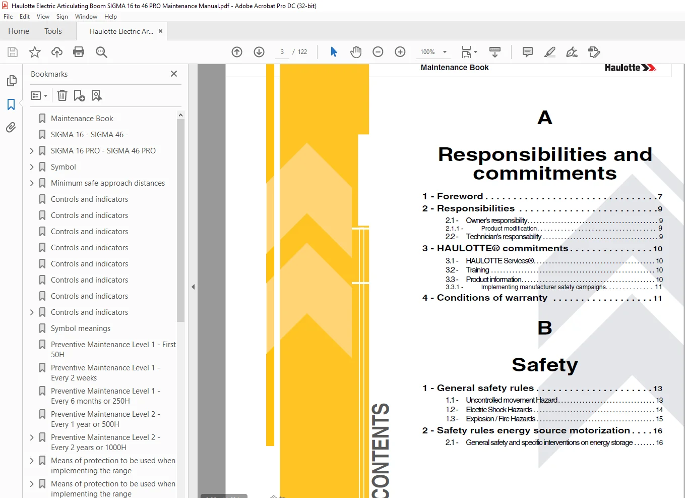
TABLE OF CONTENTS:
Haulotte Forklift SIGMA 16 – SIGMA 46 Maintenance Manual – PDF DOWNLOAD
Maintenance Book 1
SIGMA 16 – SIGMA 46 – 1
SIGMA 16 PRO – SIGMA 46 PRO 1
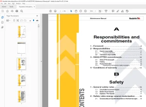
A 3
Responsibilities and commitments 3
1 – Foreword 7 3
2 – Responsibilities 9 3
21 – Owner’s responsibility 9 3
211 – Product modification 9 3
22 – Technician’s responsability 9 3
3 – HAULOTTE® commitments 10 3
31 – HAULOTTE Services® 10 3
32 – Training 10 3
33 – Product information 10 3
331 – Implementing manufacturer safety campaigns 11 3
4 – Conditions of warranty 11 3
B 3
Safety 3
1 – General safety rules 13 3
11 – Uncontrolled movement Hazard 13 3
12 – Electric Shock Hazards 14 3
13 – Explosion / Fire Hazards 15 3
2 – Safety rules energy source motorization 16 3
21 – General safety and specific interventions on energy storage 16 3
C 4
Familiarization 4
1 – HAULOTTE Activ’Screen 2 17 4
2 – List of actuators and sensors 23 4
21 – Sensors and actuators 23 4
3 – Consumables (Oils) 27 4
31 – Hydraulic oil 27 4
32 – Gear motor oil 28 4
33 – Cylinder storage oil 28 4
34 – Grease 29 4
35 – Consumables 30 4
4 – Movement speed 31 4
D 4
Inspection and maintenance schedule 4
1 – Inspection program 33 4
2 – Daily inspection 33 4
3 – Preventive maintenance 34 4
4 – Periodic inspection 38 4
5 – Major inspection 40 4
Machine sheets 5
MP0001 – Wheel tightening procedure 41 5
MP0006 – Hydraulic oil filter replacement 43 5
MP0011 – Wear pad check 47 5
MP0013 – Hydraulic tank level 49 5
MP0014 – Emptying the hydraulic tank 53 5
MP0015 – Load cell tightness check 57 5
MP0016 – Rotary cylinder tightness check 61 5
MP0019 – Torque tightening of the slew ring 65 5
MP0027 – Steering system greasing 71 5
MP0028 – Greasing the pads 75 5
MP0043 – Draining the wheel reducer 79 5
MP0044 – Greasing the turntable rotation gearbox 85 5
MP0049 – Battery electrolyte level 89 5
MP0051 – Rotary cylinder tightness check 93 5
MP0052 – Check the electric motor’s carbon brushes 95 5
MS0285 – Maintenance implementation 99 5
MS0360 – Placing the machine in maintenance configuration 101 5
E 5
Electric and hydraulic diagrams 5
1 – Electric diagram 108 5
2 – Hydraulic diagram 118 5
F 5
Records 5
1 – Intervention register 121 5
Responsibilities and commitments 7
1 – Foreword 7
You have just purchased a HAULOTTE® product and we would like to thank you for your business 7
The Aerial Work Platform is a mechanical device primarily designed and manufactured with the intent to position people with the necessary tools and material to overhead elevated temporary workplaces All other uses or alterations/modifications to the 7
This manual provides the owner, operator and field service technician all necessary and detailed informations on preventive maintenance to be carried out on their machine 7
It is recommended that only trained personnel should perform these operations 7
We would particularly like to draw your attention to : 7
• Compliance with safety instruction (machine, use, environment) 7
• Use of the equipment within the performance limits 7
This maintenance book is specific to the HAULOTTE® products listed on the cover page of this manual 7
It is the on-site maintenance technician’s duty to carry out the regular maintenance work recommended by HAULOTTE® 7
This maintenance work is essential for correct machine operation 7
If regular maintenance is not carried out, this may : 7
• Jeopardize operator safety 7
• Reduce machine reliability and shorten its service life 7
• Cause machine malfunction 7
• Void the warranty 7
In order to guarantee optimal maintenance, we recommend that you use HAULOTTE® expert technicians with genuine spare parts, documentation and the required tools 7
Symbol 8
2 – Responsibilities 9
21 – Owner’s responsibility 9
The owner (or hirer) has the obligation to inform technician of the instructions contained in the Operator Manual and Maintenance Book 9
The owner (or hirer) has the obligation to renew all manuals or decals that are either missing or in bad condition 9
Additional decals can be ordered from HAULOTTE Services® 9
The owner (or hirer) is responsible for applying the local regulations regarding maintenance of the machine 9
211 – Product modification 9
Without the written permission from HAULOTTE®, modifying a HAULOTTE® product is a Safety concern 9
Any modification may violate Haulotte design parameters, local regulations and industry standards 9
If you desire a modification to the product, tanks to submit a request in writing to HAULOTTE® 9
22 – Technician’s responsability 9
The technician must read and understand the contents of this manual, operators manuals and the decals affixed on the machine 9
The technician must inform the owner (or hirer) if the manual or any decals are missing or in poor condition, and of any malfunction of the machine 9
3 – HAULOTTE® commitments 10
31 – HAULOTTE Services® 10
HAULOTTE Services® is at your service in all 5 continents of the world via an extensive network of its own trained technicians, who are ready to respond to your every need 10
Our HAULOTTE Services® After Sales Service is at your disposal throughout your machine’s service life to ensure the optimum use of your HAULOTTE product : 10
32 – Training 10
Would you like to train your teams to operate and/or maintain your machine HAULOTTE®? Contact your subsidiary 10
The HAULOTTE® training courses help your teams to improve their skills 10
Our trainers are experts in pedagogy, at the cutting edge of HAULOTTE® products and the latest technological innovations 10
33 – Product information 10
In a constant concern to improve the reliability and safety of its machines, HAULOTTE® provides the following documents from the site wwwe-technical-informationcom : 10
331 – Implementing manufacturer safety campaigns 11
It is essential to implement the safety campaigns issued by the manufacturer All of these campaigns are accessible on our website 11
Connect to our website : wwwhaulottecom 11
4 – Conditions of warranty 11
Our warranty conditions and extension contracts are now available on the websites of our sales network : wwwhaulottecom 11
Safety 13
1 – General safety rules 13
Before performing any maintenance interventions, place the machine in maintenance configuration : 13
• Section MS0285 – Turntable rotation locking 13
• Section MS0360 – Placing the machine in maintenance configuration 13
11 – Uncontrolled movement Hazard 13
Be aware of uncontrolled movement and always respect the following : 13
12 – Electric Shock Hazards 14
The machine is not electrically insulated and does not provide protection from contact or proximity to electrically charged conductors 14
Always position the lift at a safe distance from electrically charged conductors to ensure that no part of the machine is within an unsafe area 14
Respect the local rules and the minimum safety distance from power lines 14
Minimum safe approach distances 14
Do not operate the machine : 14
13 – Explosion / Fire Hazards 15
2 – Safety rules energy source motorization 16
21 – General safety and specific interventions on energy storage 16
MS0360 – Placing the machine in maintenance configuration 16
If you need to perform an operation on LIVE circuits (for voltage and/or current measurement, for example) without locking out the machine, make sure that you have : 16
Reminder of voltages and currents present on the machine : 16
Familiarization 17
1 – HAULOTTE Activ’Screen 2 17
Upon starting and during operation of the machine, the LCD screen “Activ’Screen” located on the ground control box displays in real time the machine operating status 17
Controls and indicators 17
Controls and indicators 17
Controls and indicators 18
Controls and indicators 19
Controls and indicators 20
Controls and indicators 21
Controls and indicators 21
Controls and indicators 22
Low battery water level : 22
2 – List of actuators and sensors 23
21 – Sensors and actuators 23
Sensors and actuators – 1 23
Sensors and actuators – 2 24
Sensors and actuators – 3 25
3 – Consumables (Oils) 27
31 – Hydraulic oil 27
Hydraulic oils must comply with the following requirements : 27
• Antifoam and deaeration 27
• Anti-wear, anti-shear and antioxydant 27
• Rust and corrosion inhibitors (copper) 27
Biodegradable oils may be used if they comply with the following requirements : 27
The recommended viscosity grades depending on the environmental conditions are as follows : 27
32 – Gear motor oil 28
The recommended oil is EP type, the characteristics of which comply with standards MIL-L-2105 and API GL5 28
33 – Cylinder storage oil 28
If a cylinder is not used, the surface of the cylinder rod may be exposed to a corrosive environment (Example : When new equipment is stored before shipping ) 28
1 time per month, apply oil diluted in a solvent (Recommendations : UNIL OPAL PROTECT SHX 12) 28
Procedure : 28
34 – Grease 29
35 – Consumables 30
4 – Movement speed 31
To allow checking operation, refer to the following table about originally time per movement If the values measured by test are not equal to the following : 31
• Do not use the machine 31
• Setting updating is needed 31
Always check speed movement from the ground control box 31
Inspection and maintenance schedule 33
1 – Inspection program 33
The machine must be inspected at regular intervals in accordance with the requirements set out in the country of use and at least once a year The purpose of the inspection is to detect any defect which could lead to an accident during routine use of 33
Inspections and maintenance must be carried out by a qualified company or person chosen by the owner of the machine 33
The results of these visits must be recorded in a safety register created by the owner This register as well as the list of competent repair persons must made available to the work inspector, government inspector and company safety committee at any 33
(*) Or according to local regulations 33
2 – Daily inspection 33
The daily inspection must be performed every day, before the start of a new work shift and at every change of user 33
This inspection is performed by and under the responsibility of the user and includes the visual and functional inspection of the machine as well as the testing of its safety systems 33
A description of the daily inspection can be found in the machine’s user manual 33
We recommend these forms to be completed daily and stored to assist with your maintenance schedule 33
3 – Preventive maintenance 34
Maintenance operations must be carried out by a qualified technician chosen by the owner and ensure that the machine operates correctly 34
Severity of operating conditions may require a reduction in time between maintenance periods 34
Maintenance operations performed must be recorded in a register / log book of the machine 34
Symbol meanings 34
Preventive Maintenance Level 1 – First 50H 34
Preventive Maintenance Level 1 – Every 2 weeks 34
Preventive Maintenance Level 1 – Every 6 months or 250H 35
Preventive Maintenance Level 2 – Every 1 year or 500H 36
Preventive Maintenance Level 2 – Every 2 years or 1000H 37
4 – Periodic inspection 38
The Periodic inspection is a thorough inspection of the operation and safety features of the machine This must take place prior to the sale or resale of the machine and every 1 year Local regulations may have specific requirements on frequency, and 38
This intervention must take place after : 38
• Extensive dismantling and reassembly 38
• Repairs involving the machine’s essential components 38
• Any accident causing stress to the machine 38
This inspection is the responsibility of the owner, and must be conducted by a qualified technician 38
Under no circumstances may this inspection replace the control required by local regulations 38
Use the detailed program below 38
5 – Major inspection 40
The inspection is a thorough inspection of the machine to ensure that it is fully functional It must be carried out after 10 years then every 5 years 40
This inspection is the responsibility of the owner and must be carried out by a technician HAULOTTE Services® or an authorized and qualified person 40
In order to carry it out, contact the subsidiary HAULOTTE® or the authorized distributor 40
Machine sheets 40
Chassis 41
1 – Concerned machines 41
• SIGMA 16 – SIGMA 46 – SIGMA 16 PRO – SIGMA 46 PRO 41
2 – Concerned area 41
3 – Warning 41
4 – Risk prevention 41
Means of protection to be used when implementing the range 41
5 – You will need 42
6 – Procedure 42
• Position the machine on a flat and firm surface, clear of obstructions (beware of power lines) 42
• Put the machine in stowed position, boom and arm fully retracted and lowered Jib is in transportation position and telescope is retracted 42
• Mark out the work area (barriers, cones, marking tape) 42
• Restrict access to the area (restricted access sign) 42
• Switch off the ignition and remove the ignition key 42
• Place a do not operate tag at the start/stop switch location to inform personnel that the equipment is being worked on 42
Wheel / Reduction gear : 42
• Check the tightening torque of the 8 studs : 150 Nm (110 lbfft) 42
7 – Additional operations 42
• Clean the work area 42
Chassis 43
1 – Concerned machines 43
• SIGMA 16 – SIGMA 46 – SIGMA 16 PRO – SIGMA 46 PRO 43
2 – Concerned area 43
3 – Warning 43
4 – Risk prevention 43
Means of protection to be used when implementing the range 43
5 – You will need 44
6 – Consumables 44
Hydraulic oil 44
7 – Procedure 44
• Position the machine on a flat and firm surface, clear of obstructions (beware of power lines) 44
• Put the machine in stowed position, boom and arm fully retracted and lowered 44
• Mark out the work area (barriers, cones, marking tape) 44
• Restrict access to the area (restricted access sign) 44
• Switch off the ignition and remove the ignition key 44
• Place a do not operate tag at the start/stop switch location to inform personnel that the equipment is being worked on 44
• Turn the turret 90° to improve accessibility 44
• Open the frame cover 44
• Unscrew the cap from the filter 1 45
• Screw the M6 screw into the threaded hole 45
• Remove the filter cartridge and replace it with a new one 45
• Close the cap 1 45
• Wipe away any run-off and check that the system has no leaks 45
Upper boom 47
1 – Concerned machines 47
• SIGMA 16 – SIGMA 46 – SIGMA 16 PRO – SIGMA 46 PRO 47
2 – Concerned area 47
3 – Warning 47
4 – Risk prevention 47
Means of protection to be used when implementing the range 47
5 – You will need 48
6 – Procedure 48
• Position the machine on a flat and firm surface, clear of obstructions (beware of power lines) 48
• Mark out the work area (barriers, cones, marking tape) 48
• Restrict access to the area (restricted access sign) 48
Front pads : 48
• Carefully extend the tube 48
• Check the wear on the 8 wear pads : 48
• If the chamfers ( 1 ) are visible on the pads, the pad is compliant 48
• If the chamfers are not visible on the pads, replace the pads (Service and Repair Manual) 48
Rear pads : 48
• Check the wear on the 2 upper pads : 48
• If the chamfers ( 1 ) are visible on the pads, the pad is compliant 48
• If the chamfers are not visible on the pads, replace the pads (Service and Repair Manual) 48
Chassis 49
1 – Concerned machines 49
• SIGMA 16 – SIGMA 46 – SIGMA 16 PRO – SIGMA 46 PRO 49
2 – Concerned area 49
3 – Warning 49
4 – Risk prevention 49
Means of protection to be used when implementing the range 49
5 – You will need 50
6 – Consumables 50
7 – Procedure 50
• Position the machine on a flat and firm surface, clear of obstructions (beware of power lines) 50
• Put the machine in stowed position, boom and arm fully retracted and lowered Jib is in transportation position and telescope is retracted 50
• Mark out the work area (barriers, cones, marking tape) 50
• Restrict access to the area (restricted access sign) 50
• Switch off the ignition and remove the ignition key 50
• Place a do not operate tag at the start/stop switch location to inform personnel that the equipment is being worked on 50
• Check the hydraulic oil level on the gauge placed on the side of the chassis 51
• The oil level should be between the minimum ( B ) and maximum ( A ) levels 51
• If the level is below the minimum level ( B ) : Refill the hydraulic oil reservoir ( MP0014 – Emptying the hydraulic tank) 51
8 – Additional operations 51
• Clean the work area 51
Chassis 53
1 – Concerned machines 53
• SIGMA 16 – SIGMA 46 – SIGMA 16 PRO – SIGMA 46 PRO 53
2 – Concerned area 53
3 – Warning 53
4 – Risk prevention 53
Means of protection to be used when implementing the range 53
5 – You will need 54
6 – Consumables 54
7 – Procedure 54
• Position the machine on a flat and firm surface, clear of obstructions (beware of power lines) 54
• Put the machine in stowed position, boom and arm fully retracted and lowered 54
• Mark out the work area (barriers, cones, marking tape) 54
• Restrict access to the area (restricted access sign) 54
• Switch off the ignition and remove the ignition key 54
• Place a do not operate tag at the start/stop switch location to inform personnel that the equipment is being worked on 54
• Turn the turret 90° to improve accessibility 55
• Open the frame cover 55
• Place a recipient under the hydraulic oil tank ( 1 ) 55
• Remove the drain plug under the tank and allow the oil to fully drain out 55
• Tighten the drain plug 55
• Refill the hydraulic oil reservoir 2 55
• Run several cycles with the machine and ensure that the oil is between the minimum and maximum level 55
8 – Additional operations 56
• Clean any oil traces 56
• Clean the work area 56
Platform 57
1 – Concerned machines 57
• SIGMA 16 – SIGMA 46 – SIGMA 16 PRO – SIGMA 46 PRO 57
2 – Concerned area 57
3 – Warning 57
4 – Risk prevention 57
Means of protection to be used when implementing the range 57
5 – You will need 58
6 – Procedure 58
• Position the machine on a flat and firm surface, clear of obstructions (beware of power lines) 58
• Put the machine in stowed position, boom and arm fully retracted and lowered Jib is in transportation position and telescope is retracted 58
• Mark out the work area (barriers, cones, marking tape) 58
• Restrict access to the area (restricted access sign) 58
• Switch off the ignition and remove the ignition key 58
• Place a do not operate tag at the start/stop switch location to inform personnel that the equipment is being worked on 58
Check the tightness of the platform-side load cell : 58
• Check the tightening torque on the 4 screws : Torque wrench for 215 Nm (159 ftlbs) 24 mm (094 in) pin with extension 58
Check the tightness of the jib-side load cell : 59
• Check the tightening torque on the 4 screws : Torque wrench for 215 Nm (159 ftlbs) 24 mm (094 in) socket 59
Platform 61
1 – Concerned machines 61
• SIGMA 16 – SIGMA 46 – SIGMA 16 PRO – SIGMA 46 PRO 61
2 – Concerned area 61
3 – Warning 61
4 – Risk prevention 61
Means of protection to be used when implementing the range 61
5 – You will need 62
6 – Procedure 62
• Position the machine on a flat and firm surface, clear of obstructions (beware of power lines) 62
• Put the machine in stowed position, boom and arm fully retracted and lowered Jib is in transportation position and telescope is retracted 62
• Mark out the work area (barriers, cones, marking tape) 62
• Restrict access to the area (restricted access sign) 62
• Switch off the ignition and remove the ignition key 62
• Place a do not operate tag at the start/stop switch location to inform personnel that the equipment is being worked on 62
• Place the 30 mm flat wrench on the central nut of the rotary cylinder 1 62
• Place the torque wrench equipped with a 30 mm socket at the bottom of the central screw of the rotary cylinder 2 62
• Check the torque of the rotatory cylinder central nut is at 550 Nm (405 ftlbf) 62
• Visually inspect the 8 screws on the rotary cylinder 63
Turntable 65
1 – Concerned machines 65
• SIGMA 16 – SIGMA 46 – SIGMA 16 PRO – SIGMA 46 PRO 65
2 – Concerned area 65
3 – Warning 65
4 – Risk prevention 65
Means of protection to be used when implementing the range 65
5 – You will need 66
6 – Procedure 66
• Position the machine on a flat and firm surface, clear of obstructions (beware of power lines) 66
• Put the machine in stowed position, boom and arm fully retracted and lowered Jib is in transportation position and telescope is retracted 66
• Mark out the work area (barriers, cones, marking tape) 66
• Restrict access to the area (restricted access sign) 66
• Switch off the ignition and remove the ignition key 66
• Place a do not operate tag at the start/stop switch location to inform personnel that the equipment is being worked on 66
61 – Tightening the chassis / Slew ring 66
62 – Tightening the turntable / Slew ring 67
Chassis 71
1 – Concerned machines 71
• SIGMA 16 – SIGMA 46 – SIGMA 16 PRO – SIGMA 46 PRO 71
2 – Concerned area 71
3 – Warning 71
4 – Risk prevention 72
Means of protection to be used when implementing the range 72
5 – You will need 72
6 – Consumables 72
7 – Procedure 72
• Position the machine on a flat and firm surface, clear of obstructions (beware of power lines) 72
• Put the machine in stowed position, boom and arm fully retracted and lowered Jib is in transportation position and telescope is retracted 72
• Mark out the work area (barriers, cones, marking tape) 72
• Restrict access to the area (restricted access sign) 72
• Switch off the ignition and remove the ignition key 73
• Place a do not operate tag at the start/stop switch location to inform personnel that the equipment is being worked on 73
Grease the wheel pivot : 73
• Use extreme pressure grease 73
• Grease the articulation between the wheel pivot and the chassis : 73
• Remove the 2 caps 73
• Grease the 2 points with the grease gun : Pump until a resistance is felt or greasing flowing out 73
• Clean the 2 greasing points 73
• Close the caps 73
Grease the steering connecting rod : 73
• Use extreme pressure grease 73
• Grease the steering connecting rod : 73
• Remove the cap 73
• Grease the point with the grease gun Pump until a resistance is felt or greasing flowing out 73
• Clean the greasing point 73
• Close the cap 73
Upper boom 75
1 – Concerned machines 75
• SIGMA 16 – SIGMA 46 – SIGMA 16 PRO – SIGMA 46 PRO 75
2 – Concerned area 75
3 – Warning 75
4 – Risk prevention 75
Means of protection to be used when implementing the range 75
5 – You will need 76
6 – Consumable 76
7 – Procedure 76
• Position the machine on a flat and firm surface, clear of obstructions (beware of power lines) 76
• Put the machine in stowed position, boom and arm fully retracted and lowered Jib is in transportation position and telescope is retracted 76
• Mark out the work area (barriers, cones, marking tape) 76
• Restrict access to the area (restricted access sign) 76
• Switch off the ignition and remove the ignition key 76
• Place a do not operate tag at the start/stop switch location to inform personnel that the equipment is being worked on 76
• Clean the boom : 77
• Extend the boom fully 77
• Clean the 4 sides of the boom with a clean cloth 77
• Grease the boom : 77
• Use telescopic boom grease 77
• Grease the 4 sides of the boom with the brush 77
• Retract / Extend the boom to spread the grease 77
• Clean the excess on the pads 77
Chassis 79
1 – Concerned machines 79
• SIGMA 16 – SIGMA 46 – SIGMA 16 PRO – SIGMA 46 PRO 79
2 – Concerned area 79
3 – Warning 79
4 – Risk prevention 79
Means of protection to be used when implementing the range 79
5 – You will need 80
6 – Consumables 80
7 – Procedure 80
• Position the machine on a flat and firm surface, clear of obstructions (beware of power lines) 80
• Put the machine in stowed position, boom and arm fully retracted and lowered Jib is in transportation position and telescope is retracted 80
• Mark out the work area (barriers, cones, marking tape) 80
• Restrict access to the area (restricted access sign) 80
• Switch off the ignition and remove the ignition key 80
• Place a do not operate tag at the start/stop switch location to inform personnel that the equipment is being worked on 80
• Lift the machine up with a lifting device 81
• Put the wooden wedges under the frame 81
• Put the machine on wedges 81
• Unscrew the wheel nuts 81
• Place a handling device to support the wheel 81
• Remove the last nut 81
• Pull back the assembly wheel-forklift 81
• Place a recovery tank under the wheel reducer 81
• Open the filling ( 1 ) and draining ( 2 ) caps 81
• Let the oil drain out 81
• Close the draining cap ( 1 ) 81
• Clean any oil traces 81
• Open the levelling cap ( 3 ) 82
• With a funnel, fill 1 l (022 gal US) of preconized oil 82
• The level is correct when oil flows by the levelling hole 82
• Close the filling cap ( 2 ) and the levelling cap ( 3 ) 82
• Clean the work area 82
• Using a handling device place back the wheel 82
• Manually screw wheel nuts 82
• Using a torque wrench, tighten in a crosswise sequence the wheel nuts at the torque of 150 Nm (110 lbfft) 82
• Lift the machine up with a lifting device 83
• Remove the wooden wedges under the frame 83
• Place the machine on the floor 83
Turntable 85
1 – Concerned machines 85
• SIGMA 16 – SIGMA 46 – SIGMA 16 PRO – SIGMA 46 PRO 85
2 – Concerned area 85
3 – Warning 85
4 – Risk prevention 85
Means of protection to be used when implementing the range 85
5 – You will need 86
6 – Consumables 86
7 – Procedure 86
• Position the machine on a flat and firm surface, clear of obstructions (beware of power lines) 86
• Put the machine in stowed position, boom and arm fully retracted and lowered Jib is in transportation position and telescope is retracted 86
• Mark out the work area (barriers, cones, marking tape) 86
• Restrict access to the area (restricted access sign) 86
• Switch off the ignition and remove the ignition key 86
• Place a do not operate tag at the start/stop switch location to inform personnel that the equipment is being worked on 86
• Grease the rotation worn screw : 86
• Grease the rotation bearing : 87
• Grease the rotation bearing : 87
• Raise the arm, secure by placing a chock under the axis of the lift cylinder 87
• Inside the slew ring : 87
• Grease the slew ring theeth : 87
In order to grease the slew ring well, pivot the turntable several times to access all of the teeth 87
Chassis 89
1 – Concerned machines 89
• SIGMA 16 – SIGMA 46 – SIGMA 16 PRO – SIGMA 46 PRO 89
2 – Concerned area 89
3 – Warning 89
4 – Risk prevention 90
Means of protection to be used when implementing the range 90
5 – You will need 90
6 – Consumable 90
Option EASY : 90
Option AUTO : 90
7 – Procedure 90
• Position the machine on a flat and firm surface, clear of obstructions (beware of power lines) 90
• Put the machine in stowed position, boom and arm fully retracted and lowered Jib is in transportation position and telescope is retracted 90
• Mark out the work area (barriers, cones, marking tape) 90
• Restrict access to the area (restricted access sign) 90
• Switch off the ignition and remove the ignition key 91
• Place a do not operate tag at the start/stop switch location to inform personnel that the equipment is being worked on 91
• Place the machine in maintenance configuration Refer to MS0360 Placing the machine in maintenance configuration 91
71 – Procedure to fill the batteries manually (Option EASY) 91
72 – Procedure to fill the batteries automatically (Option AUTO) 92
8 – Additional operations 92
• Clean the work area 92
Jib 93
1 – Concerned machines 93
• SIGMA 16 – SIGMA 46 – SIGMA 16 PRO – SIGMA 46 PRO 93
2 – Concerned area 93
3 – Warning 93
4 – Risk prevention 93
Means of protection to be used when implementing the range 93
5 – You will need 94
6 – Procedure 94
• Position the machine on a flat and firm surface, clear of obstructions (beware of power lines) 94
• Put the machine in stowed position, boom and arm fully retracted and lowered Jib is in transportation position and telescope is retracted 94
• Mark out the work area (barriers, cones, marking tape) 94
• Restrict access to the area (restricted access sign) 94
• Switch off the ignition and remove the ignition key 94
• Place a do not operate tag at the start/stop switch location to inform personnel that the equipment is being worked on 94
• Place the 36 mm flat wrench on the central nut of the rotary cylinder 1 94
• Place the torque wrench equipped with a 36 mm socket at the bottom of the central screw of the rotary cylinder 2 94
• Check the torque of the rotatory cylinder central nut is at 800 Nm (590 ftlbf) 94
• Visually inspect the 8 screws on the rotary cylinder 94
Chassis 95
1 – Concerned machines 95
• SIGMA 16 – SIGMA 46 – SIGMA 16 PRO – SIGMA 46 PRO 95
2 – Concerned area 95
3 – Warning 95
4 – Risk prevention 95
Means of protection to be used when implementing the range 95
5 – You will need 96
6 – Procedure 96
• Position the machine on a flat and firm surface, clear of obstructions (beware of power lines) 96
• Put the machine in stowed position, boom and arm fully retracted and lowered Jib is in transportation position and telescope is retracted 96
• Mark out the work area (barriers, cones, marking tape) 96
• Restrict access to the area (restricted access sign) 96
• Position the machine on a flat and firm surface, clear of obstructions (beware of power lines) 96
• Mark out the work area (barriers, cones, marking tape) 96
• Stow the machine 96
• Orientate the turntable to 90 ° 96
• Switch off the ignition and remove the ignition key 96
• Place a do not operate tag at the start/stop switch location to inform personnel that the equipment is being worked on 96
• Place the machine in maintenance configuration Refer to MS0360 Placing the machine in maintenance configuration 96
• Remove the cover 97
• Pull back the spring 97
• Remove the coal brush from its bracket 97
• Check the length of the coal brush 97
• Unscrew the bolt ( 1 ) 98
• Remove the coal brush 98
• Clean the motor from carbon dust by using compressed air 98
Re-installation : 98
• Screw the bolt of the new coal brush 98
• Place the coal brush in the bracket 98
• Put back the spring on the coal brush 98
• Refit the cover 98
Turntable 99
1 – Placing in configuration 99
Your safety and the safety of the people around are essential 99
Make sure the work area is clean in order to not to pollute the system of the machine 99
Before performing any maintenance interventions, place the machine in maintenance configuration 99
Placing the machine in maintenance configuration : 99
1 Place the machine on firm, level ground 99
2 Stow the machine completely 99
3 Push the E-stop button to cut off the electricity supply 99
4 Insert the turntable rotation locking pin 99
Placing in operating configuration : 99
5 Remove the turntable rotation locking pin 99
6 Pull the E-stop button 99
Chassis101
1 – Concerned area101
2 – Warning101
3 – Risk prevention102
Means of protection to be used when implementing the range102
4 – You will need102
5 – Placing the machine in maintenance configuration103
• Position the machine on a flat and firm surface, clear of obstructions (beware of power lines)103
• Mark out the work area (barriers, cones, marking tape)103
• Stow the machine103
• Restrict access to the area (restricted access sign)103
• Switch off the ignition and remove the key ( 1 ) from the ignition103
• Place a do not operate tag at the start/stop switch location to inform personnel that the equipment is being worked on104
• Turn off the circuit breaker (Opened position)104
• Open circuit: handle vertical104
• Closed circuit: handle horizontal104
• Unlock the 2 latches on each side of the battery tray104
• Remove the cover104
For each battery compartment :105
• First disconnect the negative connection cable ( A ) with an insulating 14 mm wrench105
• Then disconnect the positive connection cable ( B )105
• Place insulation caps on the battery terminals105
• Push the cables in the chassis hole105
6 – Putting in use position105
• Carry out the operations in the reverse order105
• First connect the positive connection cable ( A ) with an insulating 14 mm wrench105
• Then connect the negative connection cable ( B )105
• Apply contact grease to the cable lugs before reconnecting them105
• Use the insulated torque wrench and apply a torque of 11,5 Nm to the battery nuts105
• Position the insulation caps correctly on the battery terminals105
• Activate the circuit breaker (Closed circuit: handle horizontal)105
• Remove the “DO NOT USE” label from the ground control box105
Electric and hydraulic diagrams107
https://wwwe-technical-informationcom107
1 – Electric diagram108
Electricity part – 4000711250 F folio 02108
Lower part – PCB – 4000711250 F folio 03109
Inverter – 4000711250 F folio 04110
SPU 1/3 + CLUSTER – 4000711250 F folio 05111
SPU 2/3 – 4000711250 F folio 06112
SPU 3/3 – 4000711250 F folio 07113
Cage part-Node B 1/2 – 4000711250 F folio 08114
Cage part-Node B 2/2 – 4000711250 F folio 09115
Option – 4000711250 F folio 10116
System architecture – 4000711250 F folio 11117
2 – Hydraulic diagram118
SIGMA16 – SIGMA16 PRO – 4000700920 G – 1/2118
SIGMA16 – SIGMA16 PRO – 4000700920 G – 2/2119
Records121
IMAGES PREVIEW OF THE MANUAL:
S.M 08/24