
HD Hyundai Infracore DN03VA DN03PA DN03SA Diesel Industrial Engine Operation & Maintenance Manual
Original price was: $34.95.$19.95Current price is: $19.95.
368-page factory Operation & Maintenance Manual for HD Hyundai Infracore DN03VA DN03PA DN03SA diesel industrial engines. Covers LEE, MCE, and MFE variants with complete service, diagnostic, and rebuild procedures.
Description
HD Hyundai Infracore DN03VA DN03PA DN03SA Diesel Industrial Engine Operation & Maintenance Manual
The complete factory service reference for the DN03 series of HD Hyundai Infracore electronically controlled industrial diesel engines. This 368-page Operation & Maintenance Manual covers the DN03VA, DN03PA, and DN03SA models together with the associated LEE01, LEE02, LEE06, LEE08, LEE11, MCE02, MFE00, MFE04, MFE06, MFE08, MFE10, and MFE11 engine variants. It provides the full set of operation, maintenance, diagnostic, and mechanical repair procedures required to keep these engines running to specification, from routine fluid checks through complete engine teardown and rebuild.
File Details
- Manual Type: Operation & Maintenance Manual
- Brand / Publisher: HD Hyundai Infracore
- Models Covered: DN03VA, DN03PA, DN03SA
- Engine Family: DN03
- Engine Variants: LEE01, LEE02, LEE06, LEE08, LEE11, MCE02, MFE00, MFE04, MFE06, MFE08, MFE10, MFE11
- Document Number: 950106-170001EN
- Publication Date: 2024.12
- Language: English
- Page Count: 368
- File Format: PDF
Chapters Covered
- 1. General Introduction — General Information, Danger Warning Caution and Note, General Instructions, Cautions for Starting the Engine, Cautions for Inspection and Repair, General Repair, Other Safety Instructions, Use of Genuine Parts, Emission Information, REGULATION (EU) 2017/654 ANNEX XV, Engine Maintenance, Biodiesel Blend Fuel, HVO, GTL, Fuel Requirements
- 2. Operation and Maintenance — Starting and Stopping the Engine, Preparing for Start, After Starting the Engine, During Operation, Stopping the Engine, ECU Learning after Engine Key Off, Break-in Period of the Engine, Check Points, Inspection after Starting the Engine, Operation in Winter, Cold Start, Preventing Coolant from Freezing, Preventing Overcooling, Engine Oil, Inspection and Repair of the Engine, Turbocharger Inspection, Intake Unit, Exhaust Unit, Lubrication System, Injection Nozzle Maintenance
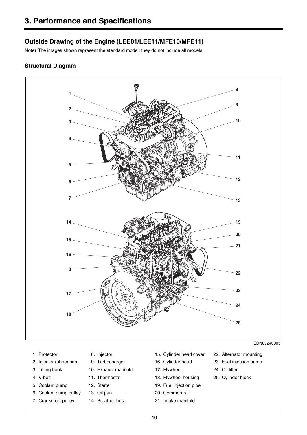
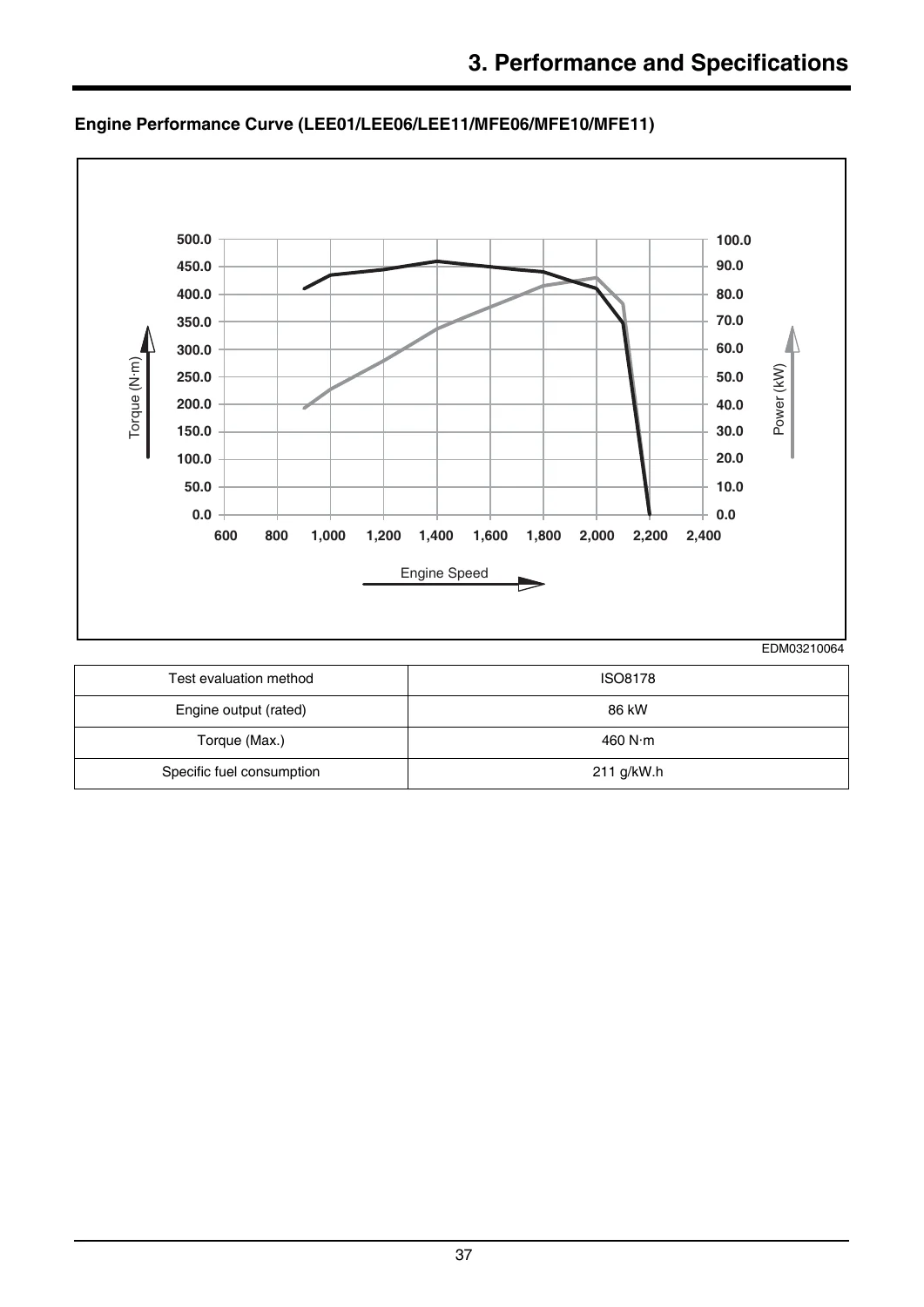
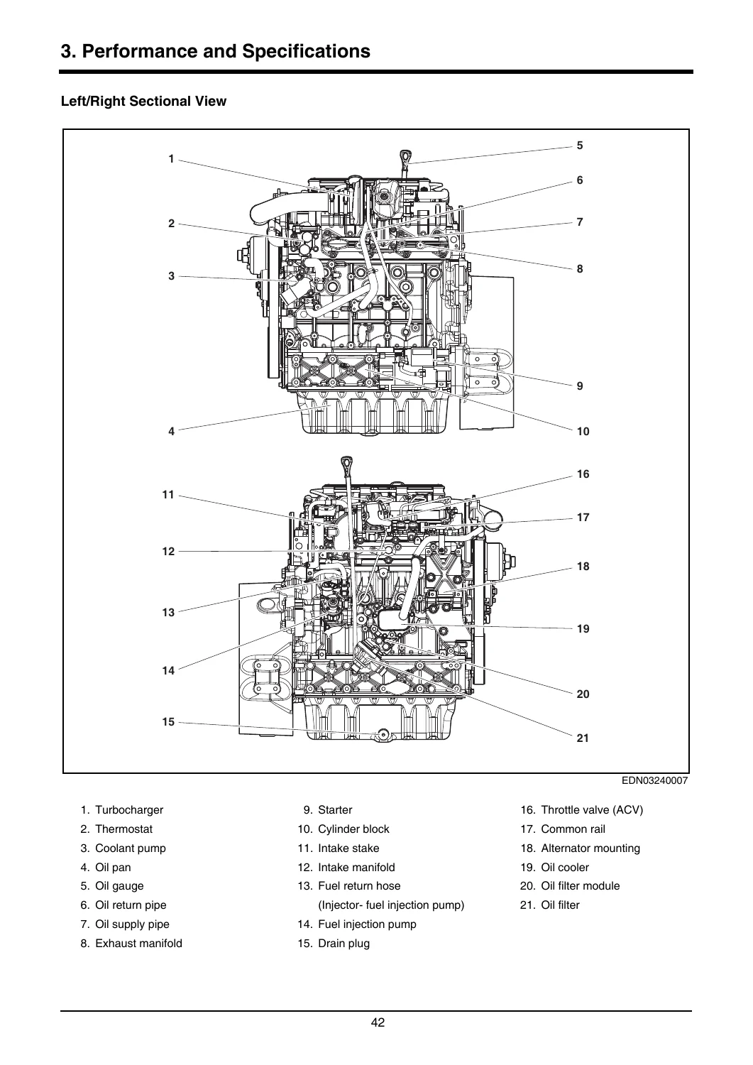
- 3. Performance and Specifications — Engine Specifications and Performance, Engine Performance Curves, Outside Drawings, Structural Diagrams, Front/Rear Views, Sectional Views, Engine Serial Number, Number Engraved on Engine and Cylinder Block, Piston Bore Class, Main Bearing Bore Class, Crankshaft Main Journal Engraving, Connecting Rod Engraving, Piston Engraving, Cylinder Head Gasket Engraving
- 4. Regular Inspections — General Information, Daily Inspections, Regular Inspection Table, General Conditions, Cooling System, Amount of Antifreeze in Winter, Coolant Capacity, Checking the Coolant, Measuring Coolant Concentration, Adding and Replacing Coolant, Lubrication System, Engine Oil Specifications, Engine Oil Capacity, Checking and Adding Engine Oil, Replacing Engine Oil, Fuel System, Fuel Specifications, Injector & Fuel Return Hose, Fuel Filter, Replacing the Fuel Filter, Bleeding Air from the Fuel Delivery Line, Draining Water from the Fuel Filter, Intake/Exhaust System, Cleaning the Air Filter, Replacing the Air Filter Element, Belt Tension
- 5. General Engine Information — Indicating Units, Unit Conversion Method, Tightening Torque of Main Parts, Tightening Torque of General Bolts, Disassembling the Engine, Engine Disassembly Order, Assembling the Engine, Order of Engine Assembly
- 6. Cooling System — General Information, Troubleshooting, Coolant Pump, Removing the Coolant Pulley, Assembling the Coolant Pump, Thermostat, Removing and Assembling the Thermostat, Checking the Thermostat, Cooling Fan, Removing and Assembling the Fan Mounting Bracket
- 7. Lubrication System — General Information, Troubleshooting, Oil Pump, Disassembling and Assembling the Oil Pump, Checking the Oil Pump, Removing and Assembling the Oil Suction Pipe, Oil Cooler, Removing and Assembling the Oil Filter Assembly, Checking the Oil Filter Assembly, Oil Pan, Removing and Assembling the Oil Pan
- 8. Fuel System — General Information, Fuel Return Hose, Injector, Injector Operating Principles, Removing and Assembling the Injector, Checking the Injector, Common Rail, Pressure Limit Valve & Rail Pressure Sensor, Injection Pipe, Removing and Assembling the Common Rail, Checking the Common Rail, Fuel Injection Pump, Removing and Assembling the Fuel Injection Pump, Removing and Assembling the Fuel Injection Pump Drive Gear
- 9. Intake/Exhaust System — Turbocharger, Troubleshooting, Handling the Turbocharger, Removing and Assembling the Turbocharger, Checking the Turbocharger, EGR (MCE02), Removing and Assembling the EGR, Intake Manifold, Removing and Assembling the Intake Manifold, Exhaust Manifold, Removing and Assembling the Exhaust Manifold, Throttle (Inlet Pipe) & the Intake Stake, Removing and Assembling
- 10. Cylinder Block/Head — General Information, Cylinder Block, Disassembling and Assembly, General Inspection, Measurement of Main Bearing Bore, Piston Bore, Camshaft Bearing, Cylinder Head, Disassembling and Assembly, Checking the Cylinder Head, Valves, Removing and Assembling Valves, Measurement of Valve Guide, Valve Stem End, Valve Step Height, Piston-Valve Gap, Checking the Valve Spring, Rocker Arms, Disassembling and Assembling, Checking the Rocker Arms and Rocker Arm Shaft, Tappet and Push rod, Removing and Assembling, Checking the Valve Tappet, Checking the Deflection of the Push rod, Camshaft, Removing and Assembling, Measuring the Camshaft Journal O.D., Flywheel Housing, Detaching and Assembling, Breather, Cylinder Head Cover, Idle Gear, Removing and Assembling, Lifting Hook, Oil Seal
- 11. Electrical System — Electric Parts, Circuit Diagram, General Information, Engine Connector, Engine Connector for ECU, Switches and Sensors (all variants), Wire Harness, Removing and Assembling the Wire Harness, Engine Control Unit (ECU), General Information, ECU Connector, ECU Input/Output, ECU Operating Conditions, Starter, General Information, Specifications, Circuit Diagram, Starter Motor Performance Curve, Removing and Assembling, Alternator
- 12. Other/Driving System — General Information, Specifications, Crankshaft, Removing and Assembling, Measuring Diameter of Crankshaft Main Journal, Measuring Crankshaft Bearing Clearance, Measuring Deflection, Disassembling and Assembling Timing Wheel, Piston, Disassembling and Assembling Pistons, Measuring Inside Diameter of Piston Pin Bore, Measuring Step Height of Piston Top Side, Measuring Piston Ring End Gap, Measuring Outside Diameter of Piston Pin, Connecting Rod, Disconnecting and Assembling, Measuring Inside Diameter of Small End, Big End, Big End Clearance, Crankshaft Pulley, Removing and Assembling, Engine Timing, Adjusting Engine Timing, Checking Gear Backlash, Checking Axial Play of Gears
- 13. Aftertreatment System — Exhaust Gas Reduction System (Tier-4 Final), General Instructions, Aftertreatment, Exhaust Gas Reduction System (Stage-V), DNOX 2.2 EVO System, DEF Tank, Supply Module, Dosing Module, Replacing the DEF Filter, Components of the DNOX 2.2 EVO System, Inspecting for Faults, DEF (Diesel Exhaust Fluid, Urea), Diesel Oxidation Catalyst (DOC), Diesel Particulate Filter (DPF), DPF Regeneration, Stage V DPF Regeneration Strategy, Cautions for Handling the SDPF Assembly, Removing SDPF Ash and Cleaning DPF
This manual is organized as a progressive service reference. It opens with safety and emissions compliance information before moving into practical operation and break-in procedures. The middle chapters cover scheduled maintenance intervals, fluid specifications, filter replacement, and system-by-system inspection. The engine mechanical section provides disassembly and assembly sequences for every major component with tightening torques, clearances, and measurement values. Electrical chapters include ECU pinouts, sensor wiring, circuit diagrams, and diagnostic procedures. The final chapters address aftertreatment systems for Tier-4 Final and Stage-V emissions, including DPF regeneration strategy and DEF handling.
Technical Depth and Service Procedures
The manual documents the complete mechanical rebuild sequence. Disassembly order begins with draining coolant and engine oil, removing the V-belt and auto tensioner, removing the starter and alternator, disconnecting the fuel return hose and fuel injection pipes, removing the cylinder head cover and injectors, then the common rail, fuel injection pump, intake manifold, exhaust manifold, turbocharger, and EGR assembly. From there the procedure continues to the cylinder head, rocker arms, push rods, camshaft, flywheel housing, idle gear, crankshaft pulley, oil pan, oil pump, connecting rods, pistons, and finally the crankshaft and main bearing caps. Assembly follows the reverse sequence with specified torque values at each stage, angle-tightening methods for critical fasteners, sealant application widths, and measurement checks for end play, backlash, and bearing clearance.
Coverage extends to the common rail fuel system with injector operating principles, pressure limit valve and rail pressure sensor service, injection pipe replacement, and fuel injection pump removal and gear timing. Turbocharger chapters cover troubleshooting, handling precautions, and assembly. The electrical section provides full circuit diagrams and pinout tables for all engine variants, including injector circuits, sensor wiring, glow plug control, fan clutch, and starter/alternator connections. The aftertreatment chapters explain DEF storage, supply module operation, dosing module service, DPF regeneration modes from passive through forced regeneration, and SDPF ash cleaning intervals.
What This Manual Enables
IMAGES PREVIEW
This HD Hyundai Infracore DN03VA DN03PA DN03SA Operation & Maintenance Manual gives a technician everything needed to keep a DN03 engine running to specification. You can perform scheduled services using the inspection interval tables, diagnose faults through the ECU and sensor wiring diagrams, disassemble and reassemble the cylinder head, crankshaft, pistons, connecting rods, and timing gear train, service the common rail fuel system, turbocharger, EGR system, and aftertreatment components, and measure every critical clearance and torque value the factory specifies. Correct procedures and exact specifications prevent premature failures, reduce downtime, and keep the engine within emissions compliance. Delivered as an instant PDF download, the manual is printable for the workshop and readable on any phone, tablet, or computer, with no shipping and no waiting.
Reviews
There are no reviews yet.