
Hino 238 258LP 268 338 Chassis Workshop Manual Volume 2/2 – S1-UNAE10A PDF Download
Original price was: $44.95.$29.95Current price is: $29.95.
Complete Volume 2 of 2 of the Hino Chassis Workshop Manual for 238, 258LP, 268, and 338 series trucks with J08E-VB and J08E-VC engines. 556 pages covering steering, power steering, front and rear axles, suspension, chassis frame, cab, electrical systems, and full wiring diagrams.
Description
Hino 238 258LP 268 338 Chassis Workshop Manual – Volume 2 of 2
This is the complete second volume of the Hino Chassis Workshop Manual (Publication S1-UNAE10A 2/2), prepared for the HINO 238, 258LP, 268, and 338 series trucks equipped with the J08E-VB and J08E-VC engine. At 556 pages, this volume covers the chassis-mounted systems in exhaustive detail: steering, power steering, front and rear axles, wheels and tires, suspension, chassis frame, cab, electrical equipment, and the complete electric wire diagram section. Every procedure, torque value, and specification is presented exactly as Hino Motors Sales U.S.A., Inc. published it.
File Details
- Manual Type: Chassis Workshop Manual (Volume 2 of 2)
- Brand: Hino
- Models Covered: HINO 238, 258LP, 268, 338 series
- Engines Covered: J08E-VB, J08E-VC
- Language: English
- Page Count: 556
- File Format: PDF
- Publication No.: S1-UNAE10A 2/2
Chapters Covered
- Steering System
- Power Steering Gear Unit
- Power Steering Pump
- Front Axle (MFS)
- Rear Axle
- Wheel and Tire
- Suspension (Leaf and Air)
- Chassis Frame
- Cab
- Electrical Equipment
- Electric Wire
Steering System
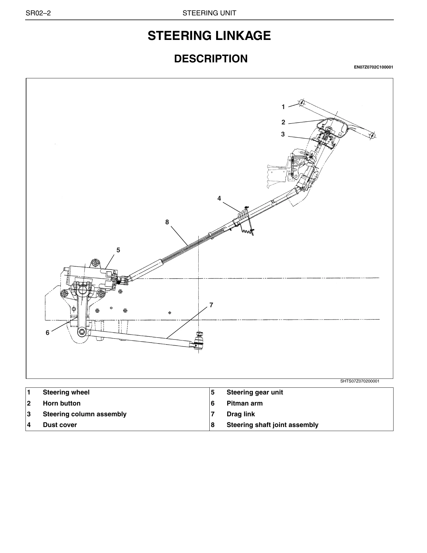
The steering chapter opens with a symptom-based troubleshooting matrix covering steering wheel shimmy, hard steering, poor return-to-center, and oil leakage. Each symptom is traced through a logical flowchart to the failed component – loose linkage, worn ball joints, power steering gear adjustment, wheel balance, tire pressure, or distorted disc wheel. The overhaul section walks through steering wheel removal using the SST steering wheel puller (S0965-01341), pitman arm removal with the SST pitman arm puller (S0965-01260), drag link dust seal replacement, and proper reinstallation with torque values for the pitman arm pinch bolt (367-423 N·m) and drag link slotted nuts (136-170 N·m). Final inspection covers steering wheel free play (0-35 mm), turning force measurement with a spring balancer, and column lock verification.
Power Steering Gear Unit
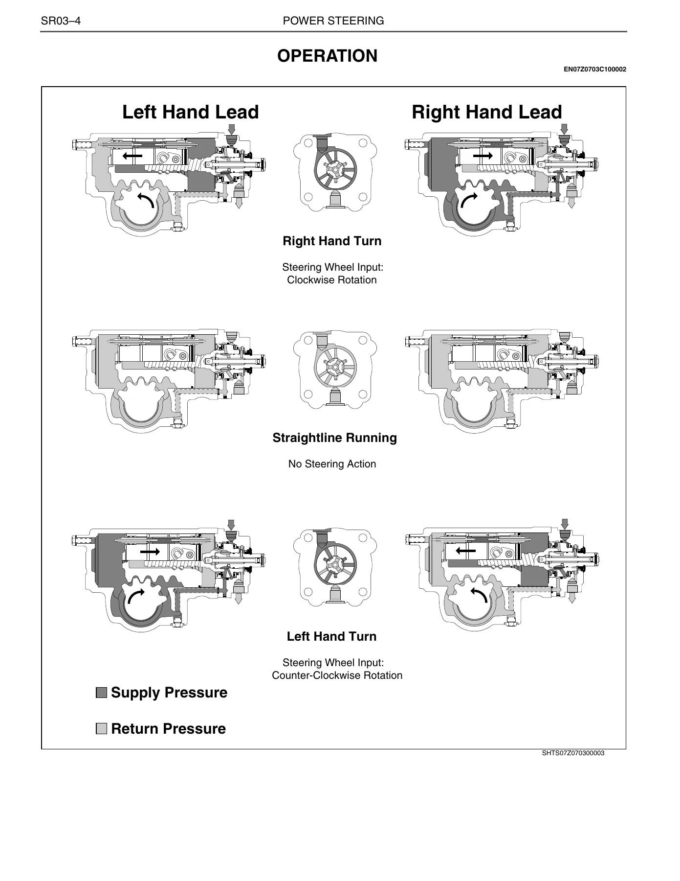
This chapter is dedicated to the TRW TAS65 integral hydraulic power steering gear. It includes complete disassembly and assembly procedures, inspection criteria for the rack piston, sector shaft, valve housing, and worm screw, plus the full poppet readjustment procedure for single gears. Critical torque specifications are listed for every fastener – side cover bolts, valve housing bolts, poppet sealing nut, and sector shaft adjusting screw jam nut. The chapter also covers approved hydraulic fluids (Dexron II, Type E/F, and specific Chevron, Mobil, Shell, Texaco, and Union products), input shaft seal replacement using the vehicle’s power steering pump to force out the old seal, and sector shaft adjustment on or off the vehicle.
Power Steering Pump
The vane-type power steering pump chapter provides relief pressure (14.0-14.7 MPa), flow rate (14.9-18.9 L/min), and a complete breakdown of the pump’s internal components – flow control valve, relief valve, rotor, cam ring, vanes, front and rear plates, and pump shaft. Disassembly and assembly procedures cover drive gear removal with a commercial puller, pump shaft removal with a sliding hammer, and careful handling of the flow control valve. Inspection criteria for the cam ring inner surface, rotor surface, vane surface, ball bearing, oil seal, and bushing are given with replacement guidance.
Front Axle (MFS)
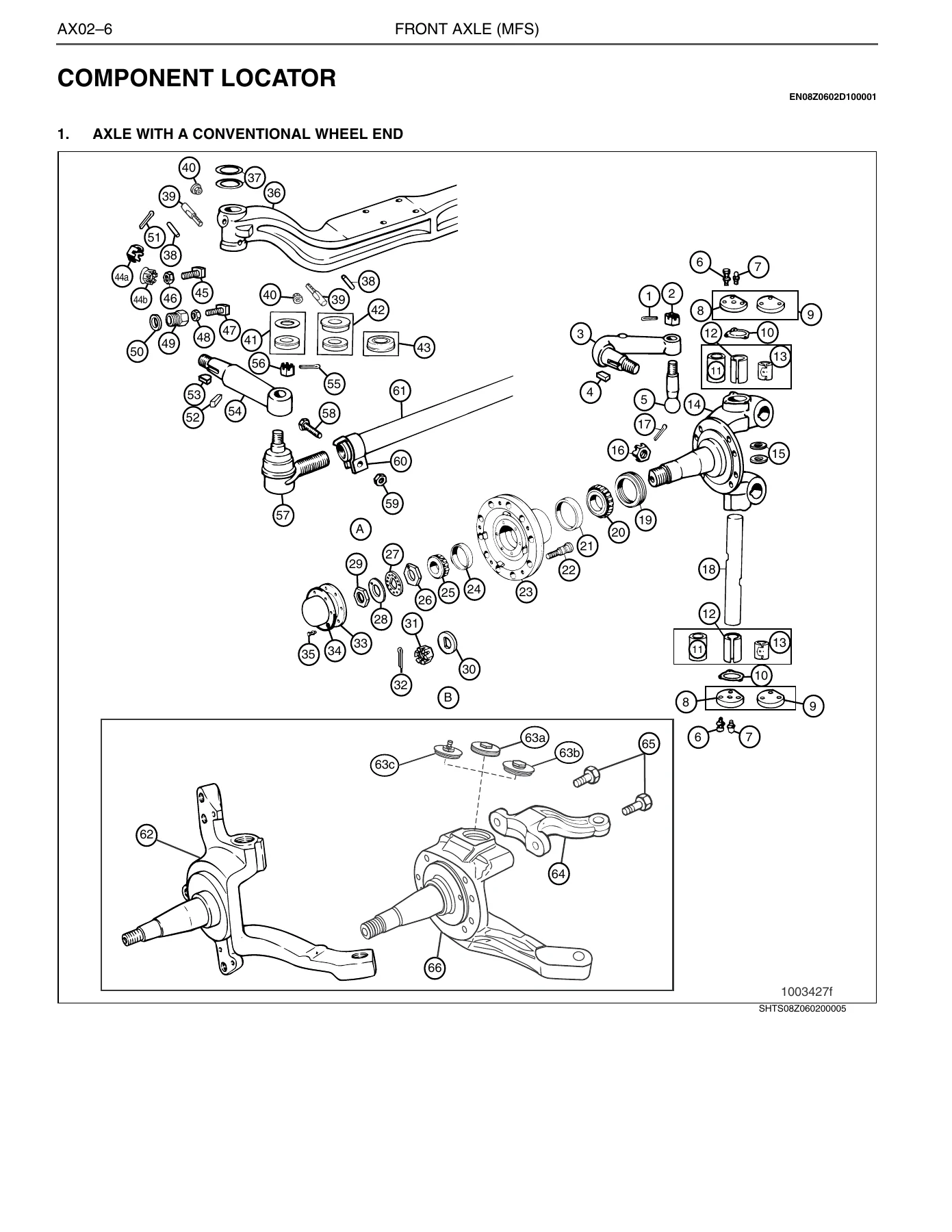
Covering the Meritor MFS-8, MFS-10, MFS-12, and MFS-14 front non-drive steer axles, this chapter opens with complete alignment specifications – camber, king pin angle, caster, toe-in, and knuckle turning angles for each model. Troubleshooting tables address tire wear, bent or broken components, and steering system pressure issues. The overhaul section details king pin bushing replacement (nylon, bronze, and Easy Steer types), steering knuckle vertical end play measurement (0.001-0.010 inch for new/rebuilt axles, 0.001-0.030 inch for in-service), tie rod end and cross tube inspection, drag link service, and wheel bearing adjustment. Torque specifications are given for steering arm bolts, tie rod end nuts, king pin caps, and draw key lock nuts.
Rear Axle
The rear axle chapter covers the RS17, RS19, RS21, and RS23 full-floating tube axles used across the Hino 238, 258LP, 268, 338, and 358 models. It includes a comprehensive speed limit data list matching rear axle gear ratios (from 4.11 to 6.14) with tire sizes (245/70R19.5 through 11R22.5) and their corresponding maximum speeds. Wheel-end service procedures for both the RS19-145 Quadraulic disc brake and RS21-145 Q Plus cam brake configurations are provided, covering hub removal, wheel bearing inspection and adjustment, oil seal replacement, and axle shaft reinstallation. Torque specifications for hub nuts, rotor attach bolts, and axle shaft fasteners are listed.
Wheel and Tire
This section covers tire load limits at various cold inflation pressures for all tire sizes used on these models, plus the speed limit data list cross-referenced by model, transmission, rear axle series, gear ratio, and tire size. Inspection procedures include tread depth measurement (1.6 mm minimum), runout checks (less than 2.5 mm for tire lateral and radial runout, less than 1.8 mm for wheel rim), and wheel/tire balancing recommendations. The overhaul section details tubeless tire disassembly and assembly using the SST lever (S0960-91210) and rubber hammer (S0960-91220), valve nut tightening torques, and wheel nut tightening specifications (610-680 N·m for both 8-stud and 10-stud configurations).
Suspension
Both leaf spring and air suspension systems are covered. The leaf suspension chapter provides front and rear spring dimensions, shock absorber specifications, and stabilizer bar data. Component locators with torque values cover U-bolts, spring pins, shackles, and shock absorber mounts. Overhaul procedures include spring pin removal with a brass rod, bushing replacement, leaf spring disassembly and reassembly with center bolt torque (90-100 N·m) and clip bolt torque (20 N·m). The air suspension section covers the Hendrickson AL-V system with height control device, including system diagrams, troubleshooting for abnormal noise and vehicle height issues, and adjustment procedures for the height control valve linkage.
Chassis Frame
Frame inspection and repair procedures cover checking for bending, twisting, rivet tightness, and cracking. The repair section details proper welding techniques including V-groove preparation, welding rod selection (3.2 mm, 4 mm, or 5 mm diameter depending on plate thickness), current settings for flat, vertical, and overhead positions, and reinforcement patching methods with plug welding hole diameters and spacing. Safety warnings cover disconnecting the battery before arc welding, protecting spring leaves from weld spatter, and using proper personal protective equipment.
Cab
The cab chapter covers the all-steel welded cab assembly, tilt hood with torsion bar and oil damper, radiator grille, doors with lock and window regulator service, driver and assistant seats, instrument panel removal, and the heater/air conditioning system. The A/C section includes HFC134a refrigerant precautions, compressor oil specifications (ND-OIL8), O-ring replacement, evacuation and charging procedures with gauge manifold readings, and a detailed troubleshooting matrix by symptom. Windshield replacement and weatherstrip affixing procedures are also included, along with front bumper component locators and torque values.
Electrical Equipment
This chapter opens with a complete electrical parts locator identifying where every relay, fuse, ECU, sensor, switch, and motor is installed – from the air conditioner relay behind the instrument panel to the ABS modulator on the frame rail. Troubleshooting tables cover the starting system, head light circuit, turn signal circuit, and tail/license plate light circuit. Relay inspection procedures are given for all six relay types used on the vehicle, with terminal voltage application diagrams. Additional coverage includes battery maintenance-free testing, fusible link inspection, combination switch continuity checks, head light relay and daytime running light ECU testing, turn signal flasher operation, wiper motor and washer pump inspection, power door lock circuit diagnosis, gauge and warning circuit sender testing, and power window switch and motor checks.
Electric Wire
The electric wire chapter is a complete wiring diagram reference with specification symbol lists, connector position diagrams, connector shape and part number identification, and pin lists for both in-cabin and out-of-cabin wire-to-wire connectors. This section alone spans over 200 pages of wiring diagrams organized by circuit – power supply, engine starting, charging, glow plug, spare power source, fog light, ground, meter, daytime running light, stop and turn light, room light, wiper and washer, mirror heater, remote control mirror, horn, air horn, cigarette lighter, power window, power door lock, audio, air conditioner, common rail, ABS, automatic transmission, diagnosis connector, differential lock, air dryer, air suspension dump, CAN communication, telematics, and block heater circuits. Each diagram includes wire colors, cross-sectional areas, connector numbers, and component locations.
Who This Manual Is For
This Hino chassis workshop manual is written for professional technicians, fleet maintenance shops, and serious owner-operators working on Hino 238, 258LP, 268, and 338 series trucks. If you are diagnosing a steering shimmy, rebuilding a power steering gear, replacing front axle king pin bushings, adjusting rear wheel bearings, repairing a cracked chassis frame, or tracing an electrical fault through the CAN communication network, this volume has the procedures, specifications, and diagrams you need. The troubleshooting flowcharts are particularly valuable for intermittent problems where guesswork gets expensive.
Why the Correct Procedures and Specifications Matter
Commercial truck chassis systems are not forgiving of approximate work. A pitman arm pinch bolt torqued to the wrong value can loosen and cause loss of steering control. A power steering gear poppet adjusted incorrectly can create dangerous driving characteristics or damage the pump. Front axle king pin end play outside the 0.001-0.010 inch specification will cause tire wear and handling problems. Rear wheel bearing end play beyond 0.005 inch can lead to wheel separation. This manual gives you the exact torque values, clearances, and adjustment sequences that Hino specifies – the same information dealership technicians use. The wiring diagrams are especially critical: these trucks use CAN communication between multiple ECUs, and a misdiagnosed circuit can cost hours of unnecessary parts replacement.
IMAGES PREVIEW
Instant PDF Delivery – No Shipping, No Waiting
This Hino 238 258LP 268 338 Chassis Workshop Manual Volume 2 is delivered as a PDF download immediately after payment. No shipping charges, no waiting for a package, no risk of a damaged or lost book. Open it on your shop computer, laptop, tablet, or smartphone. Print the pages you need for the job at hand – whether that is a single torque specification or an entire troubleshooting flowchart – and keep the digital file on hand for every future repair. The PDF format means you can carry the entire 556-page manual in your pocket without the weight or bulk of a printed binder.
Reviews
There are no reviews yet.