
Hino E13C-TI Diesel Engine Workshop Manual (Manual No. S5-YE13E01A) – PDF
Original price was: $29.95.$17.95Current price is: $17.95.
Complete Hino E13C-TI diesel engine workshop manual (S5-YE13E01A) covering mechanical overhaul, fuel system, turbocharger, cooling, lubrication and more. Instant PDF download.
Description
Hino E13C-TI Diesel Engine Workshop Manual – Manual No. S5-YE13E01A
This Hino E13C Diesel Engine Workshop Manual is the full factory-style reference for the E13C-TI power unit used across Hino’s heavy-duty truck range, issued under manual number S5-YE13E01A. If you are servicing an E13C-equipped Hino chassis, this Hino E13C workshop manual walks you through the engine from cold-start diagnosis to a full teardown and rebuild, all in one instant-download PDF.
File Details
- Manual type: Workshop/Service Manual
- Brand: Hino Motors
- Engine model: E13C-TI
- Manual number: S5-YE13E01A
- Language: English
- Total pages: 413
- File format: PDF, instant download
Chapters Covered
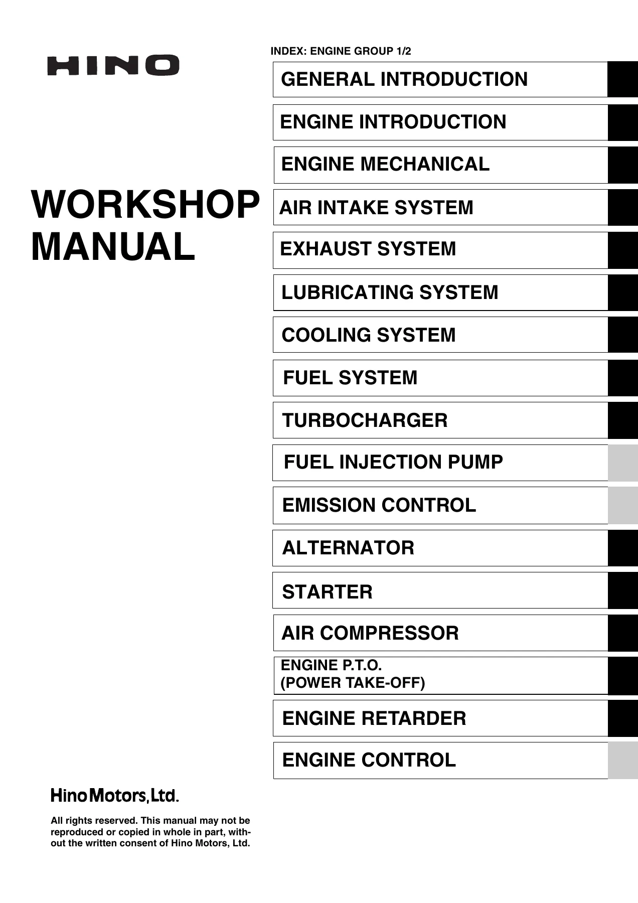
- General Introduction
- Engine Introduction — data and specifications, troubleshooting, special tools, dismounting and mounting
- Engine Mechanical — cylinder head, camshaft, crankshaft, piston and connecting rod overhaul procedures
- Air Intake System
- Exhaust System
- Lubricating System
- Cooling System
- Fuel System — including common rail components
- Turbocharger
- Alternator
- Starter
- Air Compressor
- Engine P.T.O. (Power Take-Off)
- Engine Retarder
- Fuel Control
Together these chapters give a technician everything needed to diagnose, service and rebuild the E13C-TI: full engine data and specifications, disassembly and reassembly sequences with torque values, valve timing and clearance figures, compression test procedures, and system-by-system troubleshooting tables for cooling, fuel, and combustion-related faults.
What’s Inside
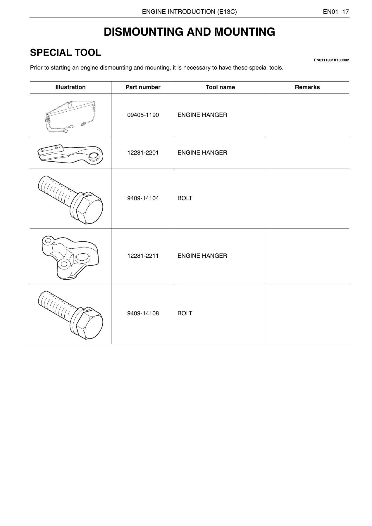
The Engine Introduction chapter opens with the core E13C-TI data block: a turbocharged and intercooled, 6-cylinder in-line, water-cooled, direct-injection diesel with a 137 x 146 mm bore and stroke, 12.913 L displacement, and a 17.5:1 compression ratio. From there the Hino E13C workshop manual moves into detailed troubleshooting charts for overheating, white smoke, and abnormal combustion, followed by the special tools needed before any overhaul and full dismounting/mounting procedures illustrated step by step.
IMAGES PREVIEW
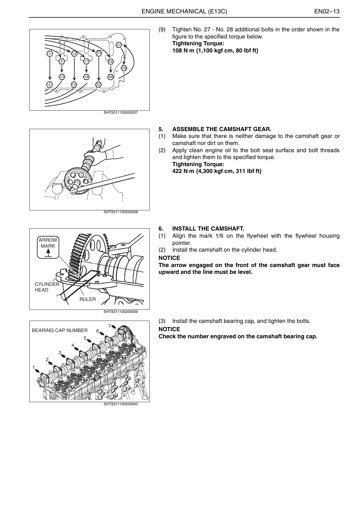
The Engine Mechanical chapter is the technical core of this Hino E13C-TI service manual, with numbered procedures and illustrations for cylinder head removal and installation, camshaft assembly and timing alignment, valve seat and valve guide replacement, piston and connecting rod work, and torque specifications for every major fastener — including cylinder head bolts, camshaft gear bolts, and connecting rod bolts, each given in N·m, kgf·cm and lbf·ft. Fuel System coverage includes the common-rail injection components, injector and rail service points, and SST usage for signal-check work during diagnosis. The Turbocharger, Air Intake, Exhaust, Lubricating, and Cooling System chapters each carry their own inspection criteria, disassembly steps, and wear-limit data, while the Alternator, Starter, Air Compressor, Engine P.T.O. and Engine Retarder chapters extend coverage to the engine-driven accessories most commonly serviced alongside the E13C-TI.
Why Technicians Use This Manual
With this Hino E13C-TI diesel engine workshop manual you can diagnose overheating, compression loss, white/black smoke, and starting problems using Hino’s own troubleshooting logic, then move straight into the correct repair procedure with the exact torque value and clearance spec in hand — rather than guessing at settings or reusing figures from a different engine family. Working from Hino’s own data keeps valve clearances, injection timing, and bolt torques within factory tolerance, which protects compression, fuel efficiency, and long-term engine reliability. This Hino E13C workshop manual PDF downloads instantly after purchase, opens on a PC, tablet, or phone, and can be printed a chapter at a time for shop-floor use — no shipping wait, no physical binder to store.
Reviews
There are no reviews yet.