
Hino FC FD GD FG GH FL FM FT GT SG Series Electrical Wiring Workshop Manual S1-YFCE18G
Original price was: $44.95.$25.95Current price is: $25.95.
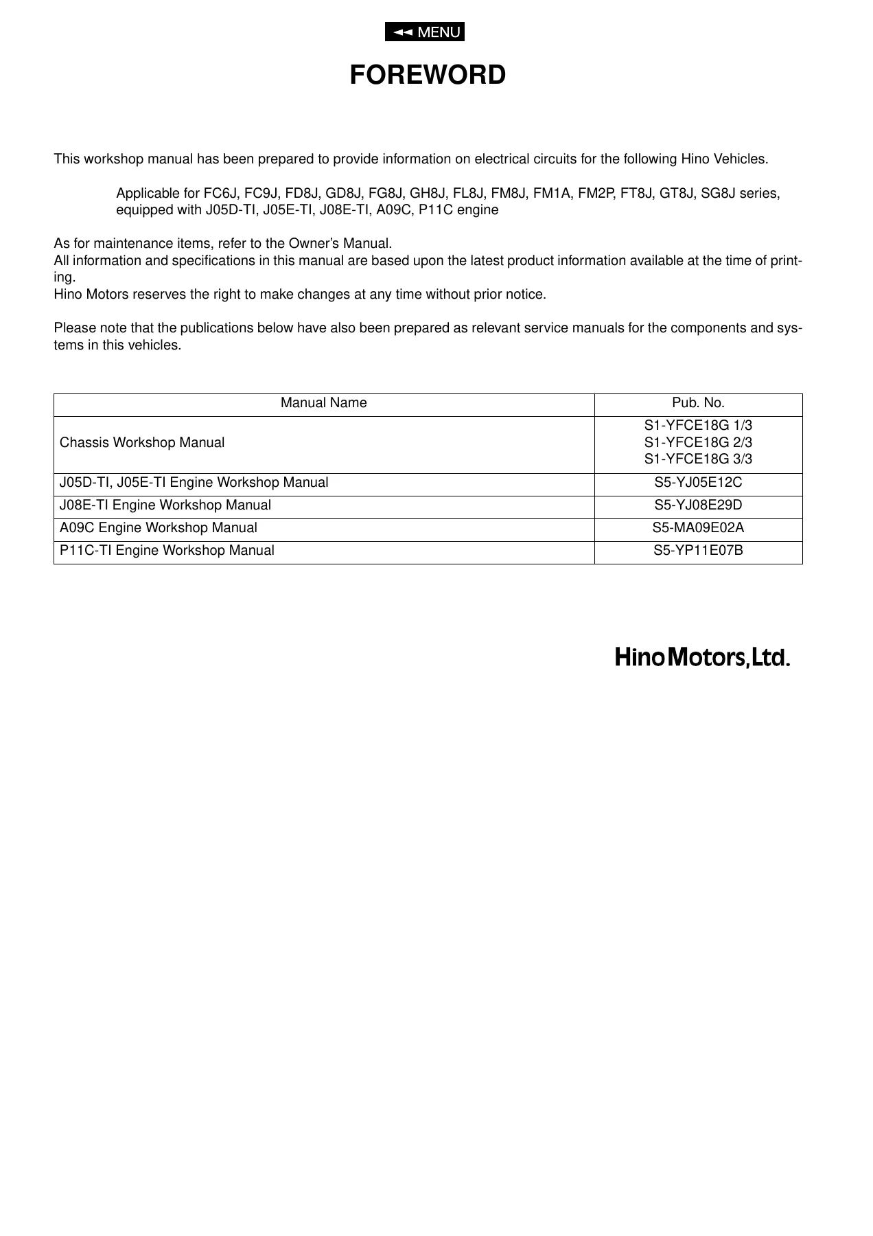
Complete electrical wiring workshop manual for Hino FC, FD, GD, FG, GH, FL, FM, FT, GT and SG series trucks. Covers J05D-TI, J05E-TI, J08E-TI, A09C and P11C engines with full circuit diagrams, connector locations, relay charts, fuse blocks and ground points across 376 pages.
Description
File Details
- Manual Type: Electrical Wiring Workshop Manual
- Brand: Hino Motors, Ltd.
- Series Covered: FC6J, FC9J, FD8J, GD8J, FG8J, GH8J, FL8J, FM8J, FM1A, FM2P, FT8J, GT8J, SG8J
- Engines Covered: J05D-TI, J05E-TI, J08E-TI, A09C, P11C
- Language: English
- Page Count: 376
- File Format: PDF
- Publication Number: S1-YFCE18G
Chapters Covered
- How to Use This Chapter
- Contents and Quick Reference
- Wiring Diagram
- Power Supply Circuit
- ETC. Spare Power Supply Circuit
- 12V Spare Power Supply Circuit
- Engine Starting Circuit (Manual Transmission)
- Engine Starting Circuit (Automatic Transmission)
- Charging Circuit
- Meter Circuit (Except Indonesia)
- Meter Circuit (Indonesia)
- Hour Meter Circuit
- Tachograph Circuit
- KIENZLE Tachograph Circuit
- Drive Master Circuit
- Headlight Circuit
- Turn, Stop and Tail Light Circuit
- Headlight Beam Control Circuit
- Backup Light Circuit (Manual and Automatic Transmission)
- Fog Light Circuit
- Headlight Autoleveling Circuit
- Working Light Circuit
- Room Light Circuit
- Power Door Lock Circuit (RHD and LHD)
- Windshield Wiper and Washer Circuit
- Power Mirror Circuit
- Horn Circuit
- Cigarette Lighter Circuit
- Seat Belt Warning Circuit
- Power Window Circuit (RHD and LHD)
- Radio/Audio Circuit
- Mirror Heater Circuit
- Keyless Entry Circuit
- Integrated Unit Circuit
- Headlight Washer Circuit
- Air Conditioner Circuit
- J Series Engine Common Rail Circuit No.1 through No.4
- TICS Circuit
- Exhaust Brake Circuit
- P11C Engine Common Rail Circuit No.2
- Engine Stop Circuit
- A09C Common Rail Circuit No.1 through No.5
- ABS+ES Start Circuit
- ABS Circuit (WABCO)
- ES Start Circuit
- Brake Lock Circuit
- Electromagnetic Retarder Circuit
- Inter-Axle Differential Lock Circuit
- Transmission Control Circuit (EATON FS6109/8209, ZF9S109/ZF9S1110/1310)
- ZF9S1310 Transmission Power Shift Circuit
- Automatic Transmission Circuit
- Cab Tilt Circuit (Single and Double Cab)
- Transmission P.T.O. Control Circuit
- Diagnosis Monitor Circuit
- Diagnosis Connector (16 Pin) Circuit
- CAN (Controller Area Network) Circuit
- Transfer Control Circuit
- Trailer Connector Circuit
- Air Dryer Heater Circuit
- VCS (Vehicle Control System) ECU Circuit No.1 through No.4
- Ground Circuit
- Wire to Wire Connector
- Junction Connector
- Connector Location
- Relay Location
- Fuse and Relay Block
- Fusible Link Block
- Wire to Wire Box
- Connector Index
This Hino electrical wiring workshop manual covers the complete electrical architecture of FC, FD, GD, FG, GH, FL, FM, FT, GT and SG series trucks. Every circuit is laid out with terminal codes, wire color codes, connector codes, serial numbers and cross-references to the connector location section. The wiring diagrams section spans nearly two hundred pages of point-to-point schematics, covering everything from the basic power supply and engine starting circuits through to CAN bus networks, ABS, VCS ECU, common rail injector control and transmission P.T.O. systems.
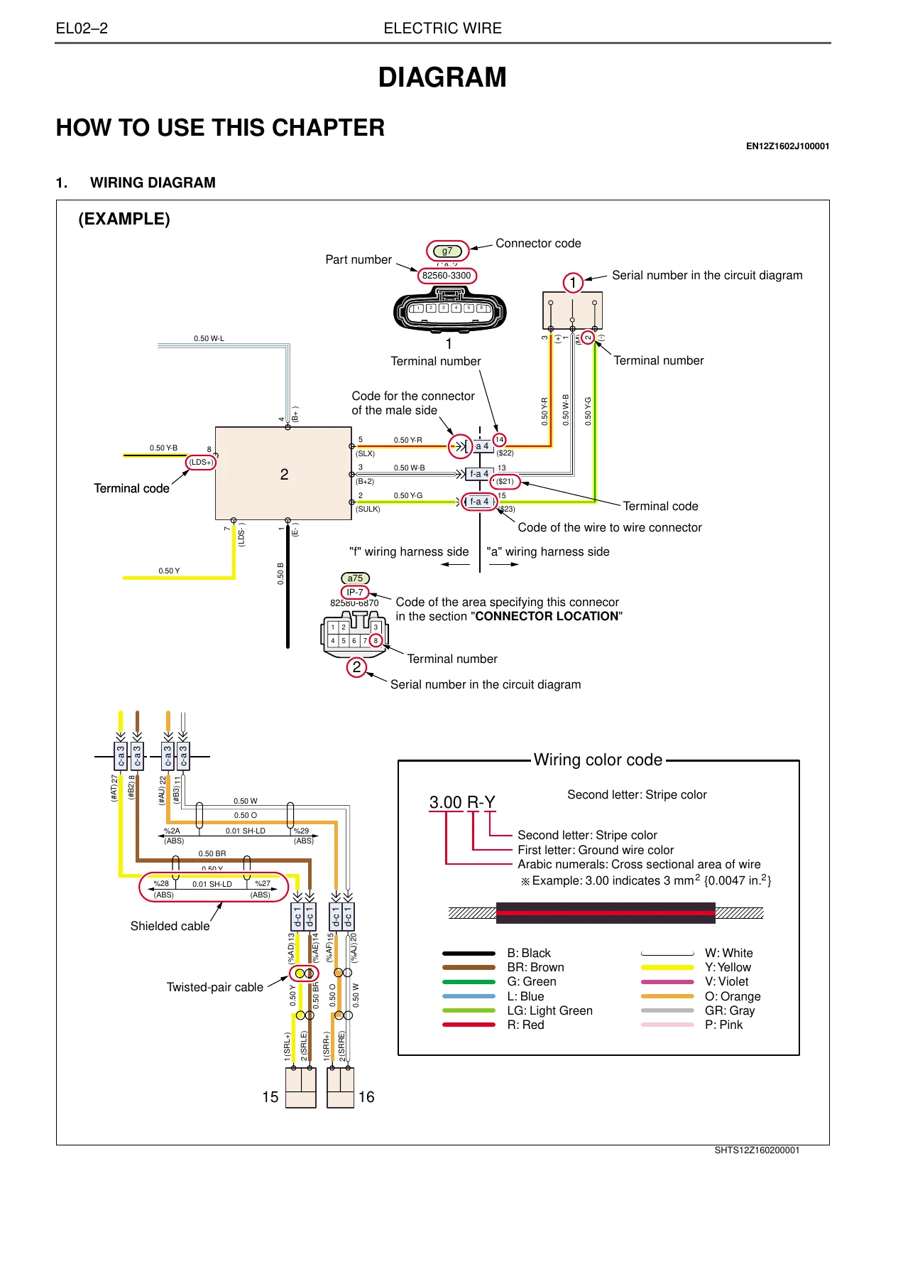
The manual opens with a dedicated “How to Use This Chapter” guide that explains the diagram symbols, connector codes, part numbers, terminal numbering, wiring color abbreviations, shielded cable and twisted-pair cable markings, and how to read the serial numbers shown in each circuit diagram. That section alone makes the rest of the document usable without guesswork.
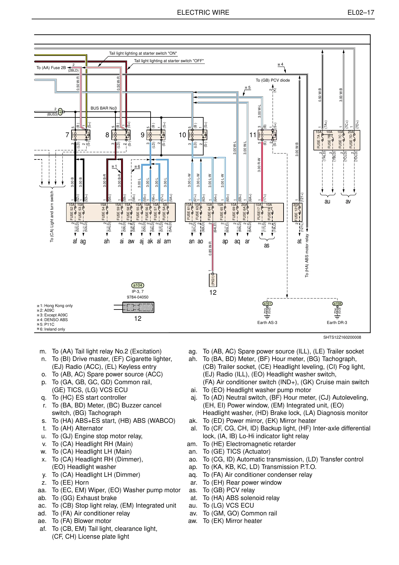
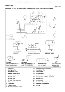
Each circuit page lists the destination component, model applicability and notes for regional variations. Where a system differs between right-hand drive and left-hand drive, between manual and automatic transmission, or between one destination market and another, the diagram is split and annotated accordingly. The common rail circuits alone cover four separate configurations for J Series engines depending on destination (Chile, Thailand, Ireland, Hong Kong, Singapore, Australia, New Zealand, Taiwan), plus dedicated sections for P11C, A09C and VCS-controlled variants.
Connector and Junction Reference
Beyond the circuit diagrams, the manual includes a full wire-to-wire connector section showing every inline harness connector with its part number, gender, terminal numbering and the harnesses it joins. The junction connector section details internal wire connections for J/C Earth, J/C CAN, common rail junctions and the various power distribution junctions. Connector location pages are organized by area code (IP for instrument panel, CA for cab, EG for engine, RR for rear) with vehicle model and drive configuration noted for each illustration.
Relay, Fuse and Fusible Link Data
Relay locations are shown for both right-hand drive and left-hand drive instrument panels and chassis, including relay names, part numbers and the circuit codes they serve. The fuse and relay block section gives terminal alignment diagrams and full fuse amperage ratings with the circuits they protect. The fusible link block section covers FL A, FL 1 through FL 6 and FL 12 with their amperage ratings and the systems they feed.
What This Manual Enables You to Do
With this electrical wiring workshop manual for Hino FC, FD, GD, FG, GH, FL, FM, FT, GT and SG series trucks, a technician can trace any circuit from battery positive through fuses, relays, switches, connectors and junction points to the component and back to ground. That means diagnosing open circuits, short circuits, high resistance connections, relay failures, ground faults and intermittent electrical problems methodically instead of by guesswork.
You can identify the correct connector and terminal for any wire, confirm wire colors and cross-sectional areas before splicing or repairing a harness, locate every ground point on the vehicle, understand how the CAN network is wired between the engine ECU, VCS ECU, automatic transmission ECU, combination meter and diagnostic connectors, and check relay and fuse assignments before condemning a component.
The manual also supports installation and troubleshooting of body electrical systems — power windows, power door locks, mirror heaters, keyless entry, air conditioning, wipers, horn, lighting, trailer connector wiring, cab tilt and the integrated unit — as well as powertrain electrical systems including common rail injector circuits, exhaust brake, P.T.O. control, transfer control, ABS and retarder circuits.
Why Correct Wiring Information Matters
Electrical faults on a modern truck can originate anywhere along a harness that runs from the cab through the chassis to the engine and rear axle. Without an accurate wiring diagram, connector pinout and ground distribution chart, diagnosis becomes a process of replacing parts until the fault disappears. This manual removes that guesswork by giving the exact wire color, terminal number, connector code and routing for every circuit on these vehicles.
It also matters because these trucks are built in many destination-specific configurations. A wire that carries an injector signal on one model may carry a different function on another. The manual’s model applicability notes and destination callouts help ensure the diagram you are reading matches the truck in front of you.
IMAGES PREVIEW
Instant PDF Delivery
The manual is delivered as a PDF download immediately after payment. There is no shipping, no waiting for a physical book and no regional restrictions. You can open it on a laptop, tablet or phone in the workshop, print the specific circuit pages you need for the job, and keep the full document for future reference. The layout is designed to be read on screen and on paper, with large fold-out style diagrams that can be zoomed or printed at full size.
Reviews
There are no reviews yet.