Hitachi 250LC-5B 250LCN-5B Hydraulic Excavator Operational Principle Technical Manual – PDF Download
Original price was: $88.95.$28.95Current price is: $28.95.
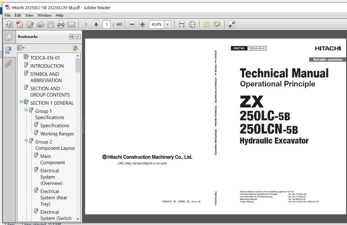
- Hitachi 250LC-5B 250LCN-5B Hydraulic Excavator Operational Principle Technical Manual
- Part No:TODCA-EN-01
Description
Hitachi 250LC-5B 250LCN-5B Hydraulic Excavator Operational Principle Technical Manual
File Details:
Hitachi 250LC-5B 250LCN-5B Hydraulic Excavator Operational Principle Technical Manual
- Manual Language:English
- Pages: 440
- Size: 10.4 MB
- Downloadable:Yes
- Format:PDF
HITACHI 250LC-5B 250LCN-5B HYDRAULIC EXCAVATOR OPERATIONAL PRINCIPLE TECHNICAL MANUAL – PDF DOWNLOAD:
Image Preview:
Description:
Hitachi 250LC-5B 250LCN-5B Hydraulic Excavator Operational Principle Technical Manual
TO THE READER
This manual is written for an experienced technician to provide technical information needed to maintain and repair this machine. The machine specification and description according to destination may be explained on this manual.
• Be sure to thoroughly read this manual for correct product information and service procedures.
• If you have any questions or comments, at if you found any errors regarding the contents of this manual, please contact using “Service Manual Revision Request Form” at the end of this manual.
ADDITIONAL REFERENCES
Please refer to the other materials (operator’s manual, parts catalog, engine technical material and Hitachi training material etc.) in addition to this manual.
MANUAL COMPOSITION
This manual consists the Technical Manual and the Workshop Manual.
• Information included in the Technical Manual: technical information needed for redelivery and delivery, operation and activation of all devices and systems, operational performance tests, and troubleshooting procedures.
• Information included in the Workshop Manual: technical information needed for maintenance and repair of the machine, tools and devices needed for maintenance and repair, maintenance standards, and removal/installation and assemble/ disassemble procedures.
Table Of Contents:
Hitachi 250LC-5B 250LCN-5B Hydraulic Excavator Operational Principle Technical Manual
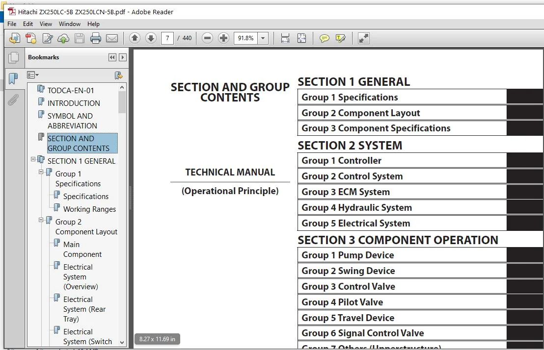
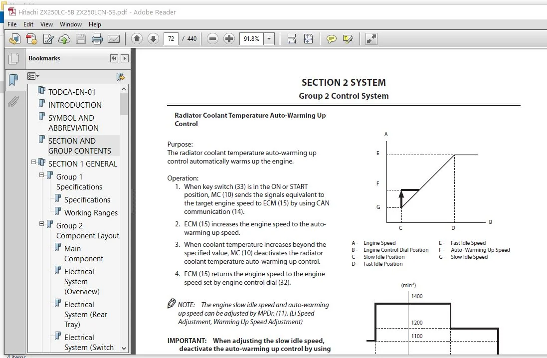
TODCA-EN-01
..................................................................................................  1
INTRODUCTION..................................................................................................  3
SYMBOL AND ABBREVIATION.......................................................................................  5
SECTION AND GROUP CONTENTS....................................................................................  7
SECTION 1
GENERAL.............................................................................................  9
	Group 1 Specifications.................................................................................... 11
		Specifications........................................................................................ 11
		Working Ranges........................................................................................ 12
	Group 2 Component Layout.................................................................................. 13
		Main Component........................................................................................ 13
		Electrical System (Overview).......................................................................... 15
		Electrical System (Rear Tray)......................................................................... 16
		Electrical System (Switch Panel)...................................................................... 17
		Electrical System (Components Related with Air Cleaner)............................................... 18
		Electrical System (Relays)............................................................................ 19
		Engine................................................................................................ 20
		Muffler Filter........................................................................................ 21
		Pump Device........................................................................................... 22
		Around Pump Device.................................................................................... 23
		Control Valve......................................................................................... 24
		Signal Control Valve.................................................................................. 24
		Swing Device.......................................................................................... 26
		Travel Device......................................................................................... 26
		5-Spool Solenoid Valve Unit........................................................................... 27
		2-Spool Solenoid Valve Unit (Muffler Filter Regeneration Control)..................................... 27
		Layout of Attachment Spec. Parts...................................................................... 28
	Group 3 Component Specifications.......................................................................... 33
		Engine................................................................................................ 33
		Engine Accessories.................................................................................... 37
		Hydraulic Component................................................................................... 38
		Electrical Component.................................................................................. 42
SECTION 2
SYSTEM.............................................................................................. 45
	Group 1 Controller........................................................................................ 47
		Outline............................................................................................... 47
		CAN Circuit........................................................................................... 48
	Group 2 Control System.................................................................................... 51
		Outline............................................................................................... 51
		Engine Control........................................................................................ 54
		Pump Control.......................................................................................... 88
		Valve Control (Standard)..............................................................................104
		Valve Control (Optional)..............................................................................124
		Other Control.........................................................................................134
	Group 3 ECM System........................................................................................145
		Outline...............................................................................................145
		Fuel Injection Control................................................................................146
		Fuel Injection Amount Correction Control..............................................................154
		EGR Control...........................................................................................156
		Preheating Control....................................................................................158
		Alarm Control.........................................................................................159
		Muffler Filter........................................................................................160
		Operation.............................................................................................161
		Muffler Filter Regenerative Control...................................................................162
	Group 4 Hydraulic System..................................................................................165
		Outline...............................................................................................165
		Pilot Circuit.........................................................................................166
		Main Circuit..........................................................................................178
		Breaker/Pulverizer/Crusher Circuit (Optional).........................................................200
	Group 5 Electrical System.................................................................................211
		Outline...............................................................................................211
		Main Circuit..........................................................................................212
		Electric Power Circuit (Key Switch: OFF)..............................................................214
		CAN Circuit...........................................................................................216
		Accessory Circuit.....................................................................................218
		Starting Circuit (Key Switch: START)..................................................................220
		Charging Circuit (Key Switch: ON).....................................................................222
		Surge Voltage Prevention Circuit......................................................................226
		Pilot Shut-Off Circuit (Key Switch: ON)...............................................................228
		Auto Shut-Down Circuit/Automatic Engine Stop Circuit at Low Temperature...............................230
		Engine Stop Circuit...................................................................................232
		Monitor Circuit.......................................................................................235
		Security Circuit......................................................................................236
		Radio Circuit.........................................................................................238
		Air Conditioner Circuit...............................................................................238
		Accessory Circuit.....................................................................................241
		Work Light Circuit....................................................................................242
		Wiper/Washer Circuit..................................................................................244
		Cab Light Circuit.....................................................................................246
SECTION 3
COMPONENT OPERATION.................................................................................251
	Group 1 Pump Device.......................................................................................253
		Outline...............................................................................................253
		Main Pump.............................................................................................254
		Regulator.............................................................................................258
		Solenoid Valve........................................................................................280
		Pilot Pump............................................................................................282
		Pump Delivery Pressure Sensor.........................................................................282
		Pump Control Pressure Sensor..........................................................................282
	Group 2 Swing Device......................................................................................283
		Outline...............................................................................................283
		Swing Reduction Gear..................................................................................284
		Swing Motor...........................................................................................285
		Swing Parking Brake...................................................................................286
		Valve Unit............................................................................................288
	Group 3 Control Valve.....................................................................................301
		Outline...............................................................................................301
		Hydraulic Circuit.....................................................................................324
		Flow Combiner Valve...................................................................................330
		Main Relief Valve.....................................................................................332
		Overload Relief Valve (with Make-Up Function).........................................................336
		Regenerative Valve....................................................................................340
		Anti-Drift Valve......................................................................................350
		Flow Rate Control Valve...............................................................................354
		Digging Regenerative Valve............................................................................358
		Boom Lower Meter-In Cut Valve.........................................................................360
		Auxiliary Flow Combiner Valve and Bypass Shut-Out Valve...............................................362
	Group 4 Pilot Valve.......................................................................................367
		Outline...............................................................................................367
		Operation (Front Attachment / Swing and Travel Pilot Valves)..........................................369
		Operation (Auxiliary / Positioning Pilot Valve).......................................................377
		Shockless Function (Only for Travel Pilot Valve)......................................................382
	Group 5 Travel Device.....................................................................................383
		Outline...............................................................................................383
		Travel Reduction Gear.................................................................................384
		Travel Motor..........................................................................................386
		Parking Brake.........................................................................................388
		Travel Brake Valve....................................................................................390
		Overload Relief Valve.................................................................................394
		Travel Mode Control...................................................................................396
	Group 6 Signal Control Valve..............................................................................401
		Outline...............................................................................................401
		Pilot Port............................................................................................402
		Shuttle Valve.........................................................................................407
		Shockless Valve.......................................................................................410
		Pump 1 Flow Rate Control Valve, Pump 2 Flow Rate Control Valve, and Pump 3 Flow Rate Control Valve....414
		Flow Combiner Valve Control Spool, Swing Parking Brake Release Spool..................................416
	Group 7 Others (Upperstructure)...........................................................................417
		Pilot Shut-Off Solenoid Valve.........................................................................417
		Solenoid Valve........................................................................................419
		Hose Rupture Valve....................................................................................424
		Pilot Relief Valve....................................................................................430
		Recirculation Valve (Option)..........................................................................431
	Group 8 Others (Undercarriage)............................................................................433
		Swing Bearing.........................................................................................433
		Center Joint..........................................................................................434
		Track Adjuster (Front Idler Integrated Type)..........................................................435
SERVICE MANUAL REVISION REQUEST FORM..........................................................................439
Please Note:
⦁ This is the SAME manual used by the dealers to troubleshoot any faults in your vehicle. This can be yours in 2 minutes after the payment is made.
⦁ Contact us at [email protected] should you have any queries before your purchase or that you need any other service / repair / parts operators manual.
Van Maximus –
Abdul –
HITACHI 250LC-5B 250LCN-5B HYDRAULIC EXCAVATOR OPERATIONAL PRINCIPLE TECHNICAL MANUAL
Worth the money!