
Hitachi EH750-3 Rigid Dump Truck Workshop Manual W8R1-E-01
Original price was: $39.95.$24.95Current price is: $24.95.
Complete 582-page Hitachi EH750-3 rigid dump truck workshop manual (W8R1-E-01). Covers engine, transmission, brakes, steering, suspension, cab, hoist, and electrical systems with removal, disassembly, inspection, assembly, torque specs, and maintenance standards.
Description
Hitachi EH750-3 Rigid Dump Truck Workshop Manual (W8R1-E-01)
This is the complete Hitachi EH750-3 rigid dump truck workshop manual, publication number W8R1-E-01. At 582 pages, it is the deep-reference document a shop reaches for when a haul truck is torn down for rebuild, when a brake head needs re-sealing, when a rear axle spindle has to be cut and re-welded, or when a differential has to be set up from scratch with proper pinion depth and backlash. Every section is written for the experienced technician: removal, disassembly, inspection, assembly, installation, and the maintenance standard that tells you when a part is finished.
The manual is organized into ten sections covering the entire rigid dump truck. It does not stop at component R&R — it carries the torque charts, oil capacities, seal part references, shimming calculations, run-out limits, and wear tolerances that make a rebuild last. If you service Hitachi EH750-3 haul trucks, this is the document that keeps the work inside factory numbers.
File Details
- Manual type: Workshop Manual (maintenance, repair, removal/installation, disassembly/assembly, maintenance standards)
- Brand: Hitachi
- Model: EH750-3 Rigid Dump Truck
- Document number: W8R1-E-01
- Language: English
- Page count: 582 pages
- File format: PDF
Chapters Covered
The manual opens with a General section containing disassembly and assembly precautions, hydraulic system bleeding procedures, floating seal handling, nylon sling precautions, maintenance standard terminology, and full tightening torque data (torque charts, bolt tightening order, nut and bolt locking, pipe joint torque, O-ring seal joints, split flange clamp torque, seal tape application, low-pressure hose clamps, and periodic replacement schedules).
- Section 1 — General
- Precautions for Disassembling and Assembling
- Bleeding Air from Hydraulic System
- Floating Seal Precautions (Wheel Seal)
- Precautions for Using Nylon Sling
- Maintenance Standard Terminology
- Tightening Torque Specifications and Torque Charts
- Bolt Tightening Order, Nut and Bolt Locking, Torque Formula T-FL
- Piping Joint, O-ring Seal Joint, Split Flange Clamp Torque Values
- Periodic Replacement of Parts
- Section 2 — Service and Maintenance
- Service Position — preparing the truck, installing/removing body prop pins
- Correct maintenance and inspection procedures
- Service intervals, hour meter checks, recommended lubricants and fuel
- Electrical disconnects before welding
- Maintenance Interval Guide, greasing points, engine, transmission, hydraulic steering/brake apply, hydraulic hoist/brake cooling, brakes, fuel system, air cleaner, cooling system, electrical, suspension/wheels/tires, cab, general
- Lifting and jacking (front axle, rear axle, lifting at front and rear)
- Special tools recommended for EH750-3
- Section 3 — Engine
- Engine removal and installation (Detroit Diesel Series 60 references)
- Drive coupling removal, installation, inspection, maintenance standard
- Exhaust system removal, installation, inspection
- Air cleaner removal, installation, disassembly, inspection, assembly
- Radiator removal, inspection, installation
- Cold start systems (coolant heater, oil heater)
- Section 4 — Electrical and Instruments
- Starter mounting — removal, installation, inspection, maintenance standard
- Transmission shift control — shift selector and ECU removal/installation
- Accelerator controls — removal, installation, disassembly, inspection, assembly, APS resistance specs
- Section 5 — Power Transmission
- Transmission oil lines
- Transmission mounting — removal and installation of the Allison transmission
- Power take-off (PTO) — backlash measurement and shim pack selection, disassembly, inspection, assembly
- Front driveline — removal, installation, disassembly, inspection, assembly, run-out and slip spline limits
- Rear driveline — removal, installation, U-joint disassembly, flex effort shimming, balance specs
- Rear axle — axle shaft removal, spindle-to-banjo welding procedure, track rod, rear axle housing removal
- Differential — drive pinion shim pack calculation, half case assembly, ring gear backlash, tooth contact patterns, differential assembly worksheet
- Planetary — removal, disassembly, inspection, assembly, bearing adjustment
- Section 6 — Brake System
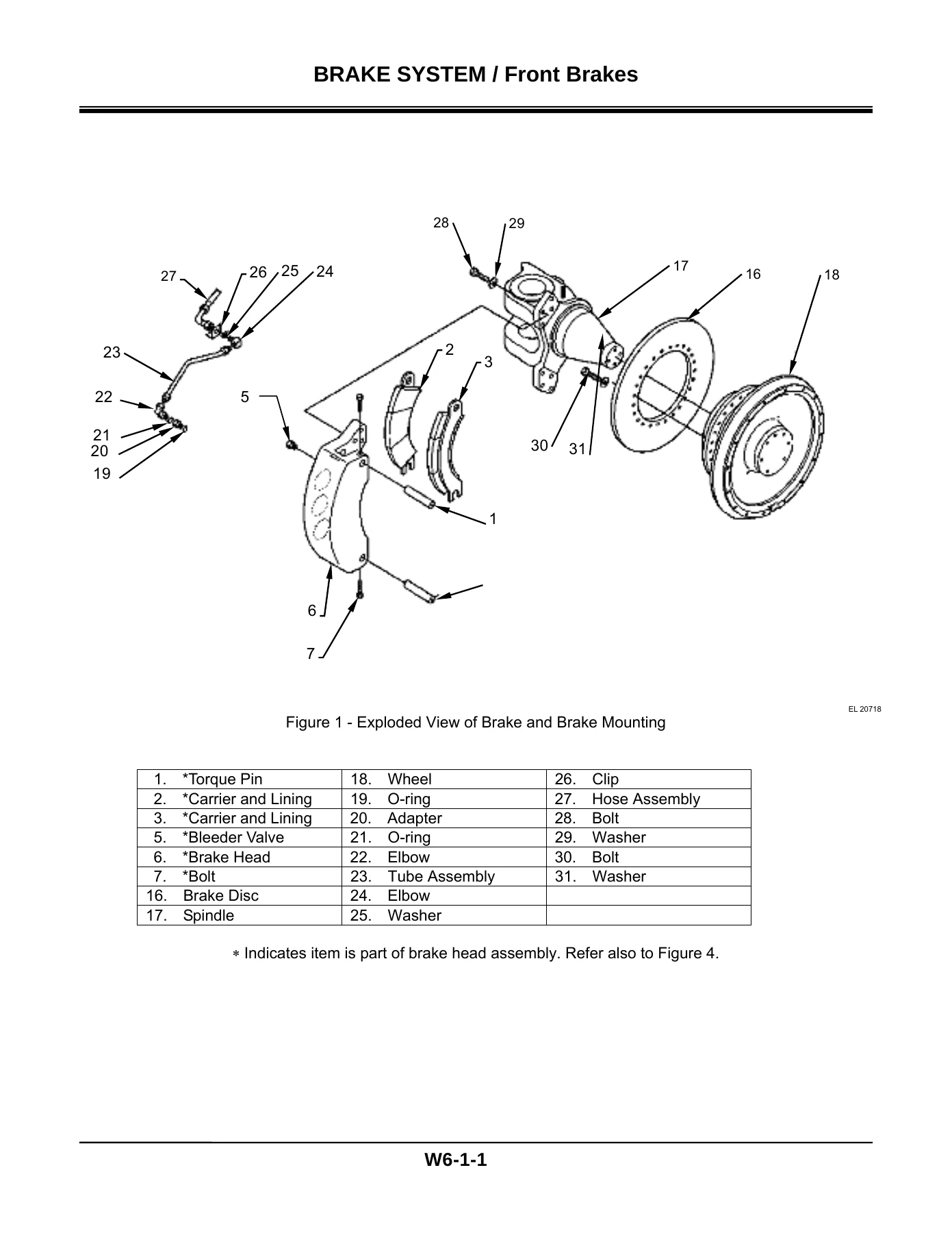
- Front brake — brake head, lining, brake disc removal/installation, disassembly, inspection, assembly
- Rear brake — removal, installation, disassembly, inspection, assembly, pressure test, brake wear initializing procedure, piston stroke adjustment
- Brake control valve — removal, installation, disassembly, inspection, assembly, adjustments
- Retarder control valve (standard and ATC)
- Brake accumulator — removal, installation, disassembly, inspection, assembly, nitrogen charging
- Brake cooling lines — supply/return piping, relief check valve, return diffuser
- Parking brake — lining and carrier, brake head, disc, support plate, adjustment procedure
- Section 7 — Steering
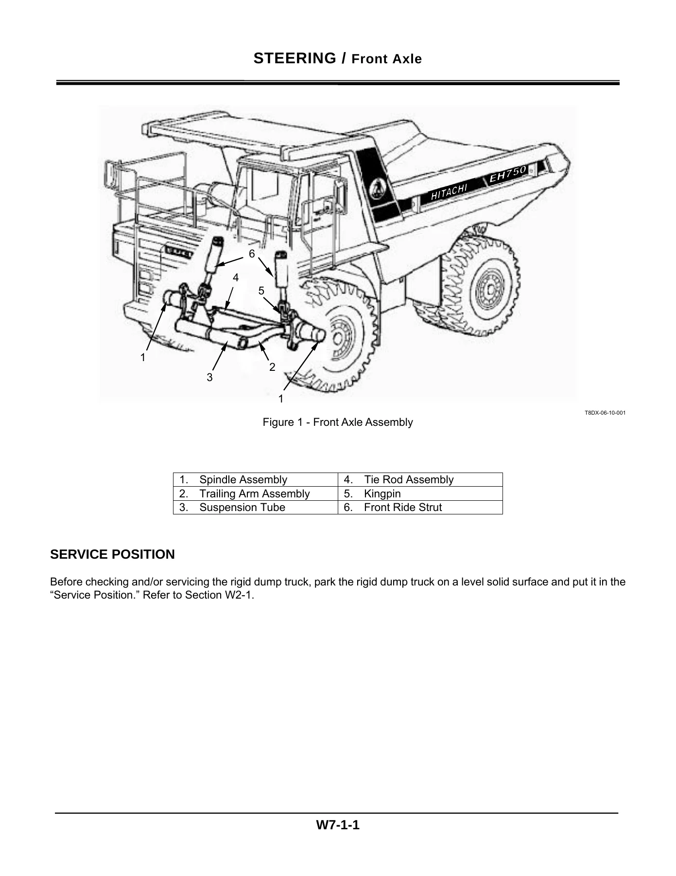
- Front axle — play check, trailing arm kingpin drill-out method, kingpin assembly with liquid nitrogen, shimming, alignment
- Steering column — removal, installation, disassembly, assembly
- Steering control valve — removal, installation, disassembly, inspection, assembly
- Steering cylinder — removal, installation, disassembly, inspection, assembly, pressure test
- Steering pump — removal, installation, disassembly, inspection, assembly, pressure checks and adjustment
- Steering accumulator — removal, installation, disassembly, assembly, inspection
- Relief check bleed valve
- Section 8 — Frame Suspension and Wheel
- Frame general — inspection, cleaning, reinforcement, straightening, welding, painting, trunnion cap, mount nose cone
- Front suspension — ride strut removal, installation, disassembly, inspection, assembly, liquid fill (Neocon-E), gas (helium) inflation, servicing, storage
- Rear suspension — removal, installation, disassembly, inspection, assembly, liquid fill, gas inflation, servicing
- Front wheel — removal, installation, disassembly, inspection, assembly, Acro-Set bearing adjustment, lubricating
- Rear wheel — removal, installation, disassembly, inspection, assembly, bearing adjustment, toric face seal inspection and installation
- Tires/rims/inflation — front and rear rim removal, installation, disassembly, inspection, assembly, inflation standards
- Section 9 — Cab
- Cab mounting — removal, installation, inspection, maintenance standard
- Air conditioning — servicing, special tools, manifold gauge readings, diagnosis, leak testing, discharging, evacuating, complete system charge, R-134a specifications
- Section 10 — Hoist Attachment
- Hoist system — removal, inspection, installation
- Hoist cylinder — removal, installation, disassembly, inspection, assembly, testing, cushion pin/orifice disc, stroke data
- Hoist valve — removal, installation, disassembly, assembly, pressure check and adjustment
- Motion control valve — removal, installation, disassembly, assembly, pressure check and adjustment
- Hoist pump — removal, installation, disassembly, inspection, assembly, maintenance standard
- Body mounting — removal, installation, disassembly, inspection, body pad shimming, rock ejector, mud guard, guard assembly, welding procedures for 400 BHN steel, body wear plates, canopy spill guard
What makes this manual useful on the shop floor is not just the coverage list — it is the depth behind it. The differential section walks through the pinion bearing shim pack calculation with a worksheet, shows the centerline fixture tool measurement, and illustrates five ring gear tooth contact patterns with corrective actions. The rear axle section documents the weld procedure for replacing a spindle on the axle housing, including preheat, interpass temperature, post-heat, and the gouge template that controls cut depth. The front suspension section explains the Neocon-E liquid fill height (X-4), the helium gas charging procedure with a manifold, and the P-1/P-1A pressure values. The front wheel section details the Acro-Set bearing adjustment with depth micrometer readings and shim pack calculation. The brake sections cover wet disc brake wear initialization, piston stroke adjustment with Loctite 242, and pressure testing at 8,400 kPa. Every one of these is the kind of procedure that is difficult to reconstruct from memory and expensive to get wrong.
What This Workshop Manual Lets You Do
With this manual you can perform a full engine removal and installation, rebuild the drive coupling, service the exhaust and air cleaner systems, remove and install the radiator, and diagnose the cold start system. You can pull the Allison transmission, set up a power take-off with correct backlash and shim pack, service both drivelines including U-joint flex effort shimming, rebuild the rear axle and differential to specified backlash and tooth contact, and rebuild the planetary hubs. Brake work is fully covered — front and rear brake heads, linings, discs, control valve, retarder valve, accumulators, cooling lines, and parking brake adjustment. Steering coverage includes the complete front axle trailing arm kingpin procedure, steering column, control valve, cylinder, pump, accumulator, and RCB valve. Frame and suspension work includes ride strut liquid fill and gas charging, wheel bearing adjustment, and tire/rim service. The cab and air conditioning section covers mounting and R-134a system service. The hoist section covers the cylinder, valve, motion control valve, pump, and body mounting including shimming of the body pads and guide brackets.
Getting a rigid dump truck back into service correctly depends on following the manufacturer’s sequence and hitting the manufacturer’s numbers. This manual provides both. Torque values are given throughout in N·m, kgf·m, and lbf·ft. Service limits are stated for every wearable part. Procedures are illustrated with exploded views and section drawings. The maintenance interval guide tells you what to inspect at daily, 250-hour, 500-hour, 1000-hour, 1200-hour, 6-month, 2500-hour, and yearly intervals. That structure is exactly what is needed to keep an EH750-3 running safely and predictably.
IMAGES PREVIEW
The manual is delivered as an instant PDF download after purchase. There is no shipping and no waiting for a physical book. You can open it on a shop laptop, tablet, or phone, search for a torque value or a seal orientation, print the pages you need for a specific job, and keep the full 582-page reference in your service library.
Reviews
There are no reviews yet.