
Hitachi Ex135 & EX215 Excavator Engine Technical Workshop Manual (604.06.817) – PDF Download
Original price was: $78.95.$27.95Current price is: $27.95.
- Hitachi Ex135 & EX215 Excavator Engine Technical Workshop Manual
- Part No:604.06.817
Description
Hitachi Ex135 & EX215 Excavator Engine Technical Workshop Manual (604.06.817)
File Details:
Hitachi Ex135 & EX215 Excavator Engine Technical Workshop Manual (604.06.817)
- Manual Language:English
- Pages: 205
- Size: 5.79 MB
- Downloadable:Yes
- Format:PDF
HITACHI EX135 & EX215 EXCAVATOR ENGINE TECHNICAL WORKSHOP MANUAL (604.06.817) – PDF DOWNLOAD:
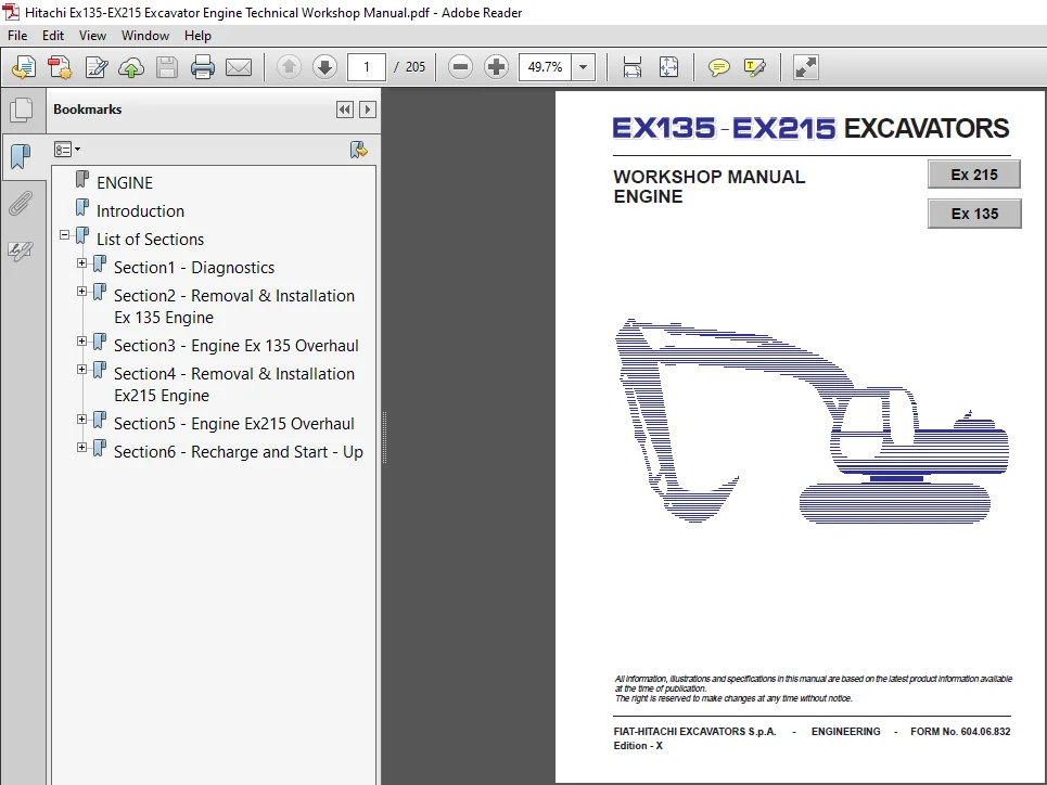
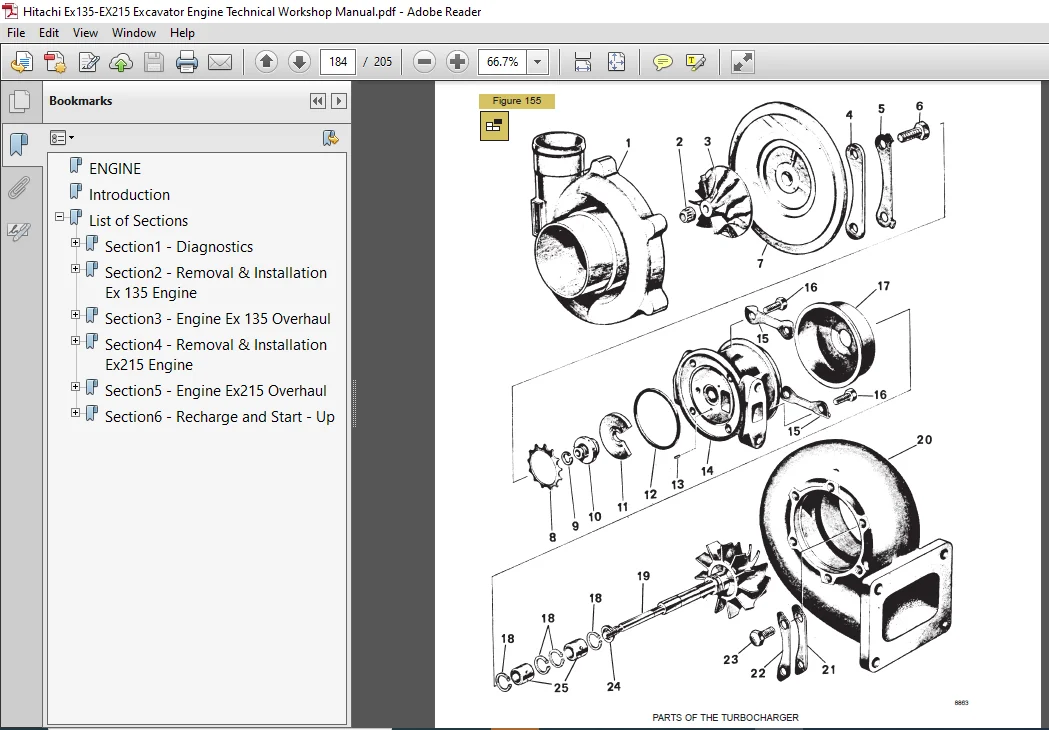
Image Preview:
Description:
Hitachi Ex135 & EX215 Excavator Engine Technical Workshop Manual (604.06.817)
TO THE READER
This manual is written for an experienced technician to provide technical information needed to maintain and repair this machine.
– Be sure to thoroughly read this manual for correct information concerning the service procedures.
– If you have any questions or comments, or if you found any errors regarding the contents of this manual
ADDITIONAL REFERENCES
• Please refer to the materials listed below in addition to this service manual:
– Operator’s Manual
– Spare Parts Catalog
SERVICE MANUAL COMPOSITION
• The complete service manual consists of four books:
– Technical Manual – Operational Principle
– Technical Manual – Troubleshooting
– Excavator Workshop Manual
– Engine Workshop Manual
– The Technical Manual-Operational Principle includes the technical information concerning the operation of main devices and systems.
– The Technical Manual -Troubleshooting includes the technical information needed for operational performance tests, and troubleshooting procedures.
– The Excavator and the Engine Workshop Manuals include information needed for maintenance and repair of the machine, tools and devices needed for maintenance and repair, maintenance standards, removal/installation and assembly/disassembly procedures.
Table Of Contents:
Hitachi Ex135 & EX215 Excavator Engine Technical Workshop Manual (604.06.817)
ENGINE..............................................................................................................  1
Introduction........................................................................................................  2
List of Sections....................................................................................................  4
	Section1 - Diagnostics..........................................................................................  5
		Diagnostics ................................................................................................  6
	Section2 - Removal & Installation Ex 135 Engine................................................................. 17
		Engine/Pumps Assembly Removal............................................................................... 18
			Air Conditioner......................................................................................... 21
			Electrical Connections.................................................................................. 21
			Hydraulic Pumps......................................................................................... 22
			Engine/Pumps Assembly Lifting........................................................................... 22
		Engine/Pumps Assembly Installation.......................................................................... 23
			Tightening Torques...................................................................................... 23
		Filling..................................................................................................... 24
			Fuel System Air Bleeding................................................................................ 25
			Filling The Cooling Sistem.............................................................................. 26
			Hydraulic System Oil Refilling.......................................................................... 27
	Section3 - Engine Ex 135 Overhaul............................................................................... 28
		Specifications and data..................................................................................... 30
		Mounting clearances - Data.................................................................................. 33
		Graphic Representation and Symbols.......................................................................... 40
		Tightening torques.......................................................................................... 41
		Special tools............................................................................................... 42
		Stripping down the engine in the Workshop................................................................... 44
		Repairs - Cylinder block - Checks and measurements.......................................................... 50
			Replacement of cylinder liners.......................................................................... 51
		Camshaft - Bushes - Valve Lifters........................................................................... 52
		Cam pitch and bearing journal alignment check............................................................... 53
		Driven toothed wheel replacement............................................................................ 53
		Bush replacement............................................................................................ 53
		Valve lifters............................................................................................... 54
			Replacement of valve lifters............................................................................ 54
			Mounting of valve lifters - camshaft.................................................................... 55
		Crankshaft.................................................................................................. 56
		Main and connecting rod bearing journals.................................................................... 56
		Check of main bearing journal alignment..................................................................... 57
		Replacement of driving toothed wheel steering and oil pump.................................................. 58
		Mounting of main bearings................................................................................... 58
		Checking of main bearing journal mounting clearance......................................................... 58
			Crankshaft end play check............................................................................... 59
		Rear flywheel cover......................................................................................... 60
		Engine flywhee.............................................................................................. 60
		Replacement of engine flywheel toothed wheel................................................................ 60
		Connecting rod ± piston assembly............................................................................ 61
		Piston...................................................................................................... 61
			Piston diameter measurement............................................................................. 61
		Piston pins................................................................................................. 62
		Piston rings................................................................................................ 63
		Connecting rods............................................................................................. 63
			Check of rectangularity of connecting rod............................................................... 64
		Bushes...................................................................................................... 64
		Mounting of connecting rod - piston assembly................................................................ 65
			Connecting rod - piston mating.......................................................................... 65
			Connecting rod - piston rectangularity check............................................................ 65
			Mounting of piston rings................................................................................ 65
		Adjustment of the mounting clearance of the connecting rod journals......................................... 66
			Mounting of connecting rod covers....................................................................... 67
		Steering.................................................................................................... 67
		Check and replacement of the transmission gear wheel........................................................ 67
		Replacement of bush for transmission gear wheel............................................................. 67
			Mounting of the transmission gear wheel and adjustment of the steering.................................. 68
		Cylinder head............................................................................................... 68
			Tightness check......................................................................................... 68
		Dismounting of valves....................................................................................... 69
			Check of cylinder head bearing surface on cylinder block................................................ 69
		Valves...................................................................................................... 69
		Removal of incrustration and valve check.................................................................... 69
			Valve grinding.......................................................................................... 70
			Boring of inner surfaces of valve stem guides........................................................... 70
			Check of clearance between valve spindle and valve stem guide........................................... 70
		Refinishing of valve seats.................................................................................. 71
			Valve sealing test...................................................................................... 71
			Remounting of valves.................................................................................... 71
			Mounting of cylinder head............................................................................... 72
		Rods........................................................................................................ 73
			Mounting of valve lifter shaft and adjustment of working clearance between valves and valve liftersi.... 74
		Lubrication................................................................................................. 74
		Oil pump.................................................................................................... 74
		Oil filter.................................................................................................. 76
			Oil pump assembly....................................................................................... 76
		Cooling system.............................................................................................. 76
		Water pump.................................................................................................. 76
		Thermostat.................................................................................................. 76
			Carrying out engine assembly at work bench.............................................................. 77
		Injection pump installation and timing...................................................................... 77
		Adjustment of the driving belt tension: water pump ± generator and fan...................................... 79
		Turbocharger................................................................................................ 82
			Description............................................................................................. 82
			Necessary checks before dismounting the turbocharger from the engine.................................... 83
		Dismounting................................................................................................. 83
			Checks.................................................................................................. 85
			Mounting................................................................................................ 86
		Fuel feed................................................................................................... 88
			Dismounting............................................................................................. 88
		Calibration................................................................................................. 88
		Injection pump.............................................................................................. 89
		Marking..................................................................................................... 89
		BOSCH stock number.......................................................................................... 89
		Mode of operation........................................................................................... 90
			Feed step............................................................................................... 90
			Delivery................................................................................................ 90
			Automatic injection adjustment.......................................................................... 91
			Starting device disconnected............................................................................ 92
			Load±dependent feed start (L.F.B.)...................................................................... 93
			Description............................................................................................. 93
			Position of the governor collar in the LFB.............................................................. 94
			L.D.A. device (load±dependent feed adjustment).......................................................... 95
			Mode of operation....................................................................................... 94
			Dismounting of the injection pump....................................................................... 95
		Checks .....................................................................................................101
			Check of pressure increasing control valve..............................................................108
			Pre±adjustment of the adjustment screw for the L.D.A. device............................................109
			Lift adjustment of the L.D.A. device....................................................................110
			Adjustment of the starting dimension "MS" (only engine 8040.45).........................................112
			Calibration tables......................................................................................114
	Section4 - Removal & Installation Ex215 Engine..................................................................118
		Engine/Pumps Assembly Removal...............................................................................119
			Air Conditioner.........................................................................................122
			Electrical Connections..................................................................................122
			Hydraulic Pumps.........................................................................................123
			Engine/Pumps Assembly Lifting...........................................................................123
		Engine/Pumps Assembly Installation..........................................................................124
			Tightening Torques......................................................................................124
		Filling.....................................................................................................125
			Fuel System Air Bleeding................................................................................126
			Filling The Cooling Sistem..............................................................................127
			Hydraulic System Oil Refilling..........................................................................128
	Section5 - Engine Ex215 Overhaul................................................................................129
		Specifications and data.....................................................................................131
		Fitting data................................................................................................134
		Graphic Representations and Symbols.........................................................................141
		Tightening torques..........................................................................................142
		Tools.......................................................................................................143
		Stripping down the engine in the workshop...................................................................145
		Repeirs Cylinder block Checks and measurements..............................................................150
		Replacement of cylinder liners..............................................................................151
		Camshaft....................................................................................................152
		Bushes - valve lifters......................................................................................152
		Cam pitch and bearing journal alignment check...............................................................152
		Driven toothed wheel replacement............................................................................152
		Bushes......................................................................................................153
		Bush replacement............................................................................................153
		Valve lifters...............................................................................................154
		Replacement of valve lifters................................................................................154
			Mounting of valve lifters - Camshaft....................................................................154
		Crankshaft..................................................................................................155
		Main and connecting rod bearing journals....................................................................156
		Check of main bearing journal alignment.....................................................................157
		Replacement of driving toothed wheel steering and oil pump..................................................157
		Mounting of main bearings...................................................................................158
			Crankshaft end play check...............................................................................158
		Rear flywheel cover.........................................................................................160
		Engine flywheel.............................................................................................160
		Replacement of engine flywheel toothed wheel................................................................160
			Mounting of engine flywheel.............................................................................160
		Connecting rod -piston assembly.............................................................................160
		Piston......................................................................................................161
			Piston diameter measurement.............................................................................161
		Piston pin..................................................................................................161
			Check of correct fit between piston pin and piston......................................................161
		Piston rings................................................................................................162
		Connecting rods.............................................................................................163
			Check of rectangularity of connecting rod...............................................................164
		Bushes......................................................................................................164
		Mounting of connecting rod - piston assembly................................................................164
			Connecting rod -piston mating...........................................................................164
			Mounting of piston rings................................................................................165
		Adjustment of the mounting clearance of the connecting rod journals.........................................166
			Mounting of connecting rod covers.......................................................................166
		Steering....................................................................................................166
		Check and replacement of the transmission gear wheel........................................................166
		Replacement of bush for transmission gear wheel.............................................................167
			Mounting of the transmission gear wheel and adjustment of the steering..................................167
		Cylinder head...............................................................................................168
			Tightness check.........................................................................................168
		Dismounting of valves.......................................................................................168
			Check of cylinder head bearing surface on cylinder block................................................168
		Valves......................................................................................................169
		Removal of incrustration and valve check....................................................................169
			Valve grinding..........................................................................................169
			Check of clearance between valve spindle and valve stem guide...........................................169
		Valve stem guide............................................................................................169
			Boring of inner surfaces of valve stem guides...........................................................170
			Remounting of valves....................................................................................171
			Mounting of cylinder head...............................................................................171
			Mounting of valve lifter shaft and adjustment of working clearance between valves and valve lifters.....173
		Lubrification...............................................................................................174
		Oil pump....................................................................................................174
		Oil filter..................................................................................................176
			Oil pump assembly.......................................................................................176
		Cooling system..............................................................................................176
		Water pump..................................................................................................176
		Thermostat..................................................................................................177
			Carrying out engine assembly at work bench..............................................................177
		Injection pump installation and timing......................................................................177
		Adjustment of the tension of control belts: water pump - generator and fan..................................178
		Turbocharger................................................................................................181
			Description.............................................................................................181
			Necessary checks before dismounting the turbocharger from the engine....................................181
		Dismounting.................................................................................................182
			Checks..................................................................................................183
			Mounting................................................................................................185
		Fuel system.................................................................................................187
		Injectors...................................................................................................187
			Calibration.............................................................................................187
			Dismantling.............................................................................................187
		Injection pump with RSV speed governor......................................................................188
			L.D.A. device (delivery adjustment as a function of load)...............................................188
			Pump marking............................................................................................188
			Speed governor marking..................................................................................188
			Speed governor..........................................................................................188
			High -pressure pumping elements.........................................................................188
			Delivery valves.........................................................................................189
			Pressure control valve assembly.........................................................................189
			Fuel injector units.....................................................................................189
			Calibration tables......................................................................................191
	Section6 - Recharge and Start - Up .............................................................................194
		Starter Motor...............................................................................................195
			Quick diagnosis.........................................................................................195
			Magneti Marelli MT 67CB - 4kW...........................................................................196
			Test and checks on the vehicle Current absorption test..................................................197
			Voltage drop test on the circuit........................................................................197
			Excessive voltage drop test on the circuit..............................................................197
			Starter motor earth test................................................................................198
			Voltage drop test on the solenoid contacts..............................................................198
			Disassembly.............................................................................................199
			Assembly................................................................................................199
			Bench test..............................................................................................200
		Alternator..................................................................................................201
			Quick diagnosis.........................................................................................201
			Bosch   NL1  28V  10/55A................................................................................202
		Test and Checks the Vehicle.................................................................................203
			Maximum output test.....................................................................................203
			Pressure drop test on the circuit.......................................................................203
			Voltage drop test on the earth circuit..................................................................204
			Voltage regulator calibration test......................................................................204
			Alternator belt tensioning..............................................................................204
			Disassembly and bench test..............................................................................205
			Assembly................................................................................................205
Please Note:
⦁ This is the SAME manual used by the dealers to troubleshoot any faults in your vehicle. This can be yours in 2 minutes after the payment is made.
⦁ Contact us at [email protected] should you have any queries before your purchase or that you need any other service / repair / parts operators manual.


Conner O –
Downloaded manual, received as ordered. Thanks!