Hitachi Ex1900-5 Excavator Technical Operational Principle Manual (T18C-01-01-003) – PDF Download
Original price was: $76.95.$23.95Current price is: $23.95.
- Hitachi Ex1900-5 Excavator Technical Operational Principle Manual
- Part No:T18C-01-01-003
Description
Hitachi Ex1900-5 Excavator Technical Operational Principle Manual (T18C-01-01-003)
File Details:
Hitachi Ex1900-5 Excavator Technical Operational Principle Manual (T18C-01-01-003)
- Manual Language:English
- Pages: 206
- Size: 3.75 MB
- Downloadable:Yes
- Format:PDF
HITACHI EX1900-5 EXCAVATOR TECHNICAL OPERATIONAL PRINCIPLE MANUAL (T18C-01-01-003) – PDF DOWNLOAD:
Image Preview:
Description:
Hitachi Ex1900-5 Excavator Technical Operational Principle Manual (T18C-01-01-003)
TO THE READER
• This manual is written for an experienced technician to provide technical information needed to maintain and repair this machine.
• Be sure to thoroughly read this manual for correct product information and service procedures.
• If you have any questions or comments, at if you found any errors regarding the contents of this manual, please contact using “Service Manual Revision Request Form at the end of this manual.
ADDITIONAL REFERENCES
• Please refer to the materials listed below in addition to this manual.
• The Operator’s Manual
• The Parts Catalog
• Operation Manual of the Engine
• Parts Catalog of the Engine
• Hitachi Training Material
MANUAL COMPOSITION
• This manual consists of three portions: the Technical Manual (Operational Principle), the Technical Manual (Troubleshooting) and the Workshop Manual.
• Information included in the Technical Manual (Operational Principle): technical information needed for redeliver and delivery, operation and activation of all devices and systems.
• Information included in the Technical Manual (Troubleshooting): technical information needed for operational performance tests, and troubleshooting procedures.
• Information included in the Workshop Manual: technical information needed for maintenance and repair of the machine, tools and devices needed for maintenance and repair, maintenance standards, and removal/installation and assemble/ disassemble procedures.
Table of Contents:
Hitachi Ex1900-5 Excavator Technical Operational Principle Manual (T18C-01-01-003)
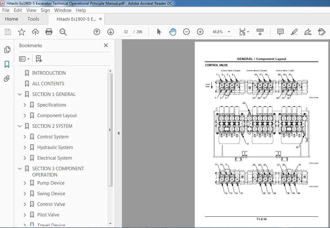
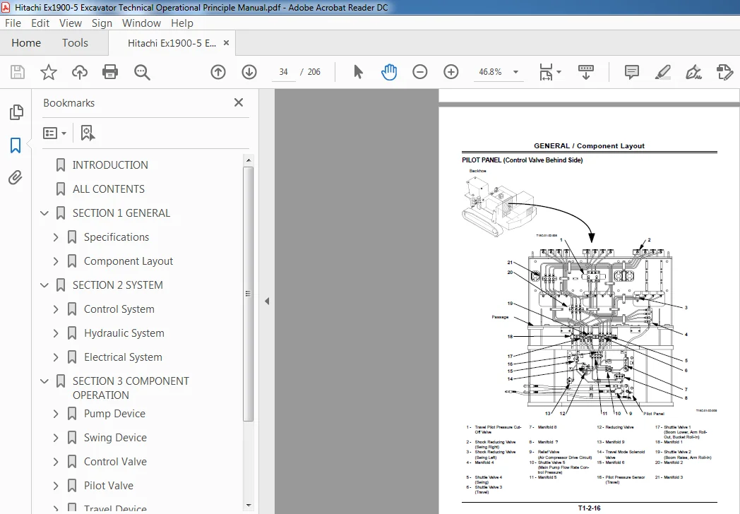
INTRODUCTION............................................................................  1
ALL CONTENTS............................................................................  3
SECTION 1 GENERAL.......................................................................  5
	Specifications......................................................................  7
		SPECIFICATIONS..................................................................  7
		WORKING RANGE (BE Backhoe)......................................................  8
		WORKING RANGE (Loading Shovel)..................................................  9
		ENGINE.......................................................................... 10
		ENGINE ACCESSORIES.............................................................. 12
		HYDRAULIC COMPONENT............................................................. 13
		ELECTRICAL EQUIPMENT............................................................ 16
		FILTER.......................................................................... 18
		OTHERS.......................................................................... 18
	Component Layout.................................................................... 19
		MAIN COMPONENTS (Overall Layout)................................................ 19
		ELECTRICAL COMPONENTS (Overall Layout).......................................... 20
		ELECTRICAL COMPONENTS (Engine and Components)................................... 21
		ELECTRICAL COMPONENTS (Engine).................................................. 22
		ELECTRICAL COMPONENTS (Electrical Equipment Box)................................ 24
		RELAY LAYOUT.................................................................... 25
		ELECTRICAL COMPONENT LAYOUT IN THE CAB.......................................... 26
		ELECTRICAL COMPONENTS (Battery Compartment)..................................... 28
		ELECTRICAL COMPONENTS (ECM Equipment Box)....................................... 30
		PUMP AND COMPONENTS............................................................. 31
		CONTROL VALVE................................................................... 32
		PILOT PANEL (Control Valve Behind Side)......................................... 34
		PILOT PANEL (Rear Side)......................................................... 36
		UNDERCARRIAGE................................................................... 37
		SWING DEVICE.................................................................... 38
		TRAVEL DEVICE................................................................... 39
		AUTO-LUBRICATION SYSTEM......................................................... 40
SECTION 2 SYSTEM........................................................................ 43
	Control System...................................................................... 45
		OUTLINE......................................................................... 45
		ENGINE CONTROL.................................................................. 47
		PUMP CONTROL.................................................................... 60
		OIL COOLER FAN MOTOR SPEED CONTROL.............................................. 66
		WIPER CONTROL................................................................... 68
		ELECTRICAL / HYDRAULIC COMBINED CIRCUIT CONTROL................................. 70
		AUTO LUBRICAITION CONTROL....................................................... 74
	Hydraulic System.................................................................... 79
		OUTLINE......................................................................... 79
		PILOT CIRCUIT................................................................... 80
		MAIN CIRCUIT.................................................................... 88
		OIL COOLER FAN MOTOR CIRCUIT.................................................... 99
		AIR CONDITIONER COMPRESSOR MOTOR  CIRCUIT....................................... 99
		PUMP TRANSMISSION OIL COOLER CIRCUIT............................................ 99
		TRAVEL SHOCK DAMPER AND TRAVEL  STOP CIRCUIT....................................100
	Electrical System...................................................................103
		OUTLINE.........................................................................103
		POWER SOURCE CIRCUIT (KEY SWITCH:OFF)...........................................104
		ACCESSORY CIRCUIT (KEY SWITCH: in  ACC position)................................116
		ENGINE START CIRCUIT............................................................118
		CHARGING CIRCUIT  (WITH KEY SWITCH ON)..........................................122
		SURGE VOLTAGE PREVENTION CIRCUIT................................................124
		ENGINE STOP CIRCUIT.............................................................126
		ENGINE STOP CIRCUIT BY EMERGENCY  ENGINE STOP SWITCH AND ENGINE  STOP SWITCH....128
SECTION 3 COMPONENT OPERATION...........................................................133
	Pump Device.........................................................................135
		OUTLINE.........................................................................135
		MAIN PUMP.......................................................................136
		REGULATOR.......................................................................138
		4-UNIT PUMP.....................................................................164
	Swing Device........................................................................165
		OUTLINE.........................................................................165
		SWING MOTOR.....................................................................166
		SWING PARKING BRAKE.............................................................168
		SWING REDUCTION GEAR............................................................169
		VALVE UNIT......................................................................170
	Control Valve.......................................................................173
		OUTLINE.........................................................................173
		PILOT PORT LOCATION.............................................................174
		HYDRAULIC CIRCUIT...............................................................175
		MAIN RELIEF VALVE AND OVERLOAD  RELIEF VALVE....................................177
		MAKEUP VALVE....................................................................178
	Pilot Valve.........................................................................179
		OUTLINE.........................................................................179
		CONSTRUCTION....................................................................180
		FUNCTION........................................................................181
		OPERATION.......................................................................182
	Travel Device.......................................................................185
		OUTLINE.........................................................................185
		TRAVEL MOTOR....................................................................186
		TRAVEL MODE CONTROL.............................................................188
		BRAKE VALVE.....................................................................190
		PARKING BRAKE...................................................................191
		TRAVEL REDUCTION GEAR...........................................................192
	Others (Upperstructure).............................................................193
		PILOT SHUT-OFF VALVE............................................................193
		AIR CONDITIONER.................................................................194
		AUTO-LUBRICATION SYSTEM.........................................................196
		OIL COOLER FAN MOTOR............................................................197
		ACCUMULATOR.....................................................................198
	Others (Undercarriage)..............................................................199
		SWING BEARING...................................................................199
		ADJUSTER CYLINDER...............................................................200
		ACCUMULATOR.....................................................................201
		CENTER JOINT....................................................................202
REVISION REQUEST FORM...................................................................205
Please Note:
⦁ This is the SAME MANUAL used by the dealerships to diagnose your vehicle
⦁ No waiting for couriers / posts as this is a PDF manual and you can download it within 2 minutes time once you make the payment.
⦁ Your payment is all safe and the delivery of the manual is INSTANT – You will be taken to the DOWNLOAD PAGE.
⦁ So have no hesitations whatsoever and write to us about any queries you may have : heydownloadss @gmail.com
Dion Madden –
Very efficient