Hitachi Ex1900-5 Excavator Technical Operational Principle Manual (TTLA-0595-EX) – PDF Download
Original price was: $71.95.$24.95Current price is: $24.95.
- Hitachi Ex1900-5 Excavator Technical Operational Principle Manual
- Part No:TTLA-0595-EX
Description
Hitachi Ex1900-5 Excavator Technical Operational Principle Manual (TTLA-0595-EX)
File Details:
Hitachi Ex1900-5 Excavator Technical Operational Principle Manual (TTLA-0595-EX)
- Manual Language:English
- Pages: 201
- Size: 37.5 MB
- Downloadable:Yes
- Format:PDF
HITACHI EX1900-5 EXCAVATOR TECHNICAL OPERATIONAL PRINCIPLE MANUAL (TTLA-0595-EX) – PDF DOWNLOAD:
Image Preview:
Sample Page From The Manual:
Hitachi Ex1900-5 Excavator Technical Operational Principle Manual (TTLA-0595-EX)
1. The signals from the auto-idle switch and pilot pressure sensors (front/swing, and travel) are sent to MC(B).
2. When signals from the pilot pressure sensors are reduced to 0.3 MPa (3 kgf/cm2, 43 psi) or less with the auto-idle switch ON, MC(B) delivers a signal to the ECM.
3. Approx. 4 seconds after the ECM receives the signal from the MC(B), the ECM drives the governor so that the engine speed is reduced to the auto-idle speed [1400 ± 50 min-1].
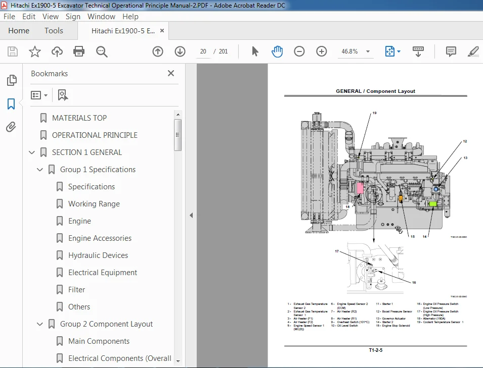
4. The engine speed sensor 2 checks the engine speed and sends a signal to the ECM. Therefore, the ECM can recognize that the engine speed is reduced to the auto-idle speed.
5. When a control lever is operated and the pilot pressure sensor signal increases to 0.49 MPa (5 kgf/cm2, 71 psi) or more, MC(B) stops sending the signal to the ECM. Then. the ECM increases the engine speed to the speed range set by the fuel lever.
Table of Contents:
Hitachi Ex1900-5 Excavator Technical Operational Principle Manual (TTLA-0595-EX)
MATERIALS TOP.........................................................................  0
OPERATIONAL PRINCIPLE.................................................................  1
SECTION 1 GENERAL.....................................................................  2
	Group 1 Specifications............................................................  4
		Specifications................................................................  4
		Working Range.................................................................  5
		Engine........................................................................  7
		Engine Accessories............................................................  9
		Hydraulic Devices............................................................. 10
		Electrical Equipment.......................................................... 13
		Filter........................................................................ 15
		Others........................................................................ 15
	Group 2 Component Layout.......................................................... 16
		Main Components............................................................... 16
		Electrical Components (Overall Layout)........................................ 17
		Electrical Components (Engine and Components)................................. 18
		Electrical Components (Engine)................................................ 19
		Electrical Components (Electrical Equipment Box).............................. 21
		Reray Latout.................................................................. 22
		Electrical Component Layout in the Cab........................................ 23
		Electrical Components (Battery Compartment)................................... 25
		Electrical Components (ECM Equipment Box)..................................... 27
		Pump and Components........................................................... 28
		Control Valve................................................................. 29
		Pilot Panel (Control Valve Behind Side)....................................... 31
		Pilot Panel (Rear Side)....................................................... 33
		Undercarriage................................................................. 34
		Swing Device.................................................................. 35
		Travel Device................................................................. 36
		Auto-Lubrication System....................................................... 37
SECTION 2 SYSTEM...................................................................... 40
	Group 1 Control System............................................................ 42
		Outline....................................................................... 42
		Engine Control................................................................ 44
		Pump Control.................................................................. 57
		Oil Cooler Fan Motor Speed Control............................................ 63
		Wiper Control................................................................. 65
		Electrical/Hydraulic Combined Circuit Control................................. 67
		Auto-Lubrication Control...................................................... 71
	Group 2 Hydraulic System.......................................................... 76
		Outline....................................................................... 76
		Pilot Circuit................................................................. 77
		Main Circuit.................................................................. 85
		Oil Cooler Fan Motor Circuit.................................................. 96
		Air Conditioner Compressor Motor Circuit...................................... 96
		Pump Transmission Oil Cooler Circuit.......................................... 96
		Travel Shock Damper and Travel Stop Circuit................................... 97
	Group 3 Electrical System.........................................................100
		Outline.......................................................................100
		Power Source Circuit..........................................................101
		Accessory Circuit.............................................................113
		Engine Start Circuit..........................................................115
		Charging Circuit..............................................................119
		Surge Voltage Prevention Circuit..............................................121
		Engine Stop Circuit...........................................................123
		Engine Stop Circuit by Emergency Engine Stop Switch and Engine Stop Switch....125
SECTION 3 COMPONENT OPERATION.........................................................130
	Group 1 Pump Device...............................................................132
		Outline.......................................................................132
		Main Pump.....................................................................133
		Regulator.....................................................................135
		4-Unit Pump...................................................................161
	Group 2 Swing Device..............................................................162
		Outline.......................................................................162
		Swing Motor...................................................................163
		Swing Parking Brake...........................................................165
		Swing Reduction Gear..........................................................166
		Valve Unit....................................................................167
	Group 3 Control Valve.............................................................188
		Outline.......................................................................188
		Pilot Port Location...........................................................171
		Hydraulic Circuit.............................................................172
		Main Relief Valve And Overload Relief Valve...................................174
		Make Up Valve.................................................................175
	Group 4 Pilot Valve...............................................................176
		Outline.......................................................................176
		Construction..................................................................177
		Function......................................................................178
		Operation.....................................................................179
	Group 5 Travel Device.............................................................182
		Outline.......................................................................182
		Travel Motor..................................................................183
		Travel Mode Control...........................................................185
		Brake Valve...................................................................187
		Parking Brake.................................................................188
		Travel Reduction Gear.........................................................189
	Group 6 Others (Upperstructure)...................................................190
		Pilot Shut-Off Valve..........................................................190
		Air Conditioner...............................................................191
		Auto-lubrication System.......................................................193
		Oil Cooler Fan Motor..........................................................194
		Accumulator...................................................................195
	Group 7 Others (Undercarriage)....................................................196
		Swing Bearing.................................................................196
		Adjuster Cylinder.............................................................197
		Accumulator...................................................................198
		Center Joint..................................................................199
Please Note:
⦁ This is not a physical manual but a digital manual – meaning no physical copy will be couriered to you. The manual can be yours in the next 2 mins as once you make the payment, you will be directed to the download page IMMEDIATELY.
⦁ This is the same manual used by the dealers inorder to diagnose your vehicle of its faults.
⦁ Require some other service manual or have any queries: please WRITE to us at [email protected]
Shepard Zev –
Good , No problems