Hitachi Ex1900-5 Excavator Technical Troubleshooting Manual (TTLA-0596-EX) – PDF Download
Original price was: $87.95.$23.95Current price is: $23.95.
- Hitachi Ex1900-5 Excavator Technical Troubleshooting Manual
- Part No:TTLA-0596-EX
Description
Hitachi Ex1900-5 Excavator Technical Troubleshooting Manual (TTLA-0596-EX)
File Details:
Hitachi Ex1900-5 Excavator Technical Troubleshooting Manual (TTLA-0596-EX)
- Manual Language:English
- Pages: 291
- Size: 3.63 MB
- Downloadable:Yes
- Format:PDF
HITACHI EX1900-5 EXCAVATOR TECHNICAL TROUBLESHOOTING MANUAL (TTLA-0596-EX) – PDF DOWNLOAD:
Image Preview:
Sample Page From The Manual:
Hitachi Ex1900-5 Excavator Technical Troubleshooting Manual (TTLA-0596-EX)
1. The circuit pressure must be increased by applying an external force while blocking the return circuit from the control valve. This measuring method is hazardous and the results obtained with this method are unreliable.
2. The oil flow rate used to set the overload relief pressure is far less than that used to set the main relief pressure. Therefore, measuring the overload pressure in the main circuit by increasing the main relief set-pressure more than the overload valve set-pressure is not a proper method. In addition, in case a main relief valve designed to leak a small quantity of oil before reliving is used, its pre-leaking start pressure must be increased more than the overload relief valve set-pressure. However, the pre-leaking start pressure is not always increased more than the overload relief valve set-pressure as the adjustable upper limit of the main relief valve set-pressure is provided. Accordingly, the overload relief valve assembly should be removed from the machine and checked on a specified test stand at a correct oil flow rate. Some overload relief valves come in contact with the control valve body to block the oil passage. When this type of overload relief valve is checked, the control valve body must be precisely finished as the test unit. Provide one control valve other than that on the machine as a test kit.
3. If the overload relief valve performance must be checked on the machine, however, measure the main relief pressure while releasing each front function respective to the measuring overload relief valve. And, assume that the overload relief valve is functioning correctly if the obtained main relief pressure is within the specified value range.
Table of Contents:
Hitachi Ex1900-5 Excavator Technical Troubleshooting Manual (TTLA-0596-EX)
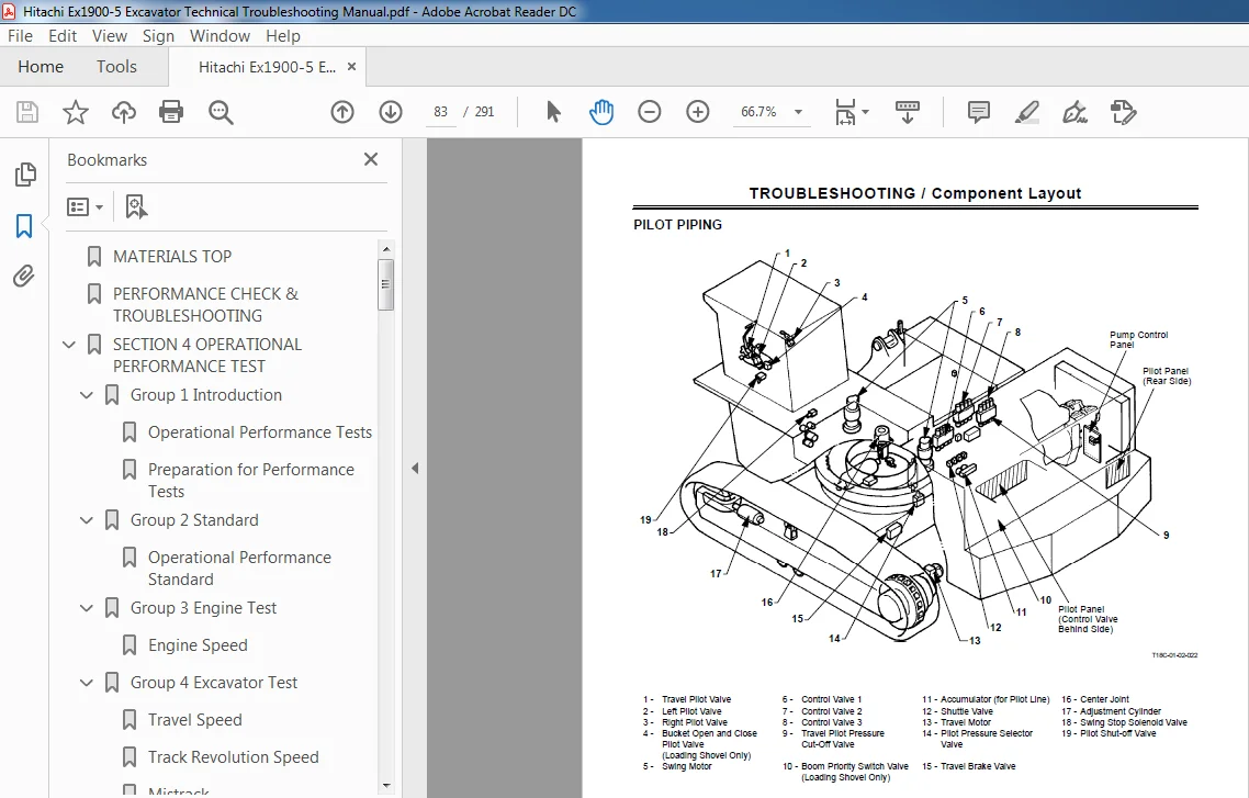
MATERIALS TOP.................................................................................................  0
PERFORMANCE CHECK & TROUBLESHOOTING...........................................................................  1
SECTION 4 OPERATIONAL PERFORMANCE TEST........................................................................  2
	Group 1 Introduction......................................................................................  4
		Operational Performance Tests.........................................................................  4
		Preparation for Performance Tests.....................................................................  5
	Group 2 Standard..........................................................................................  6
		Operational Performance Standard......................................................................  6
	Group 3 Engine Test....................................................................................... 12
		Engine Speed.......................................................................................... 12
	Group 4 Excavator Test.................................................................................... 14
		Travel Speed.......................................................................................... 14
		Track Revolution Speed................................................................................ 15
		Mistrack.............................................................................................. 16
		Travel Motor Drift Check.............................................................................. 17
		Swing Speed........................................................................................... 18
		Swing Function Drift.................................................................................. 19
		Swing Motor Leakage................................................................................... 21
		Maximum Swingable Slant Angle......................................................................... 22
		Swing Bearing Play.................................................................................... 23
		Hydraulic Cylinder Cycle Time......................................................................... 25
		Cylinder Drift........................................................................................ 27
		Control Lever Operating Force......................................................................... 29
		Control Lever Stroke.................................................................................. 30
		Boom Raise/Swing Combined Operation Check............................................................. 31
	Group 5 Component Test.................................................................................... 32
		Primary Pilot Pressure Check.......................................................................... 32
		Pilot Secondary Pressure.............................................................................. 33
		Main Relief Pressure.................................................................................. 35
		Overload Relief Pressure.............................................................................. 39
		Main Pump Flow Rate Measurement....................................................................... 41
		Oil Cooler Fan Motor Draive Pump Flow Rate Measurement................................................ 49
		Swing Motor Drainge................................................................................... 57
		Travel Motor Drainge.................................................................................. 59
SECTION 5 TROUBLESHOOTING..................................................................................... 62
	Group 1 General........................................................................................... 64
		Introduction.......................................................................................... 64
		Diagnosing Procedure.................................................................................. 65
	Group 2 Component Layout.................................................................................. 68
		Main Components (Overall Layout)...................................................................... 68
		Electrical Components (Overall Layout)................................................................ 69
		Electrical Components (Battery Compartment)........................................................... 70
		Electrical Components (Engine)........................................................................ 71
		Electrical Components (Engine and Components)......................................................... 73
		Electrical Components (ECM Equipment Box)............................................................. 74
		Electrical Components (Electrical Equipment Box)...................................................... 75
		Control Valve......................................................................................... 79
		Swing Device.......................................................................................... 81
		Travel Device......................................................................................... 82
		Pilot Piping.......................................................................................... 83
		Pilot Panel (Control Valve Behind Side)............................................................... 84
		Pilot Panel (Rear Side)............................................................................... 86
		Pump and Components................................................................................... 87
		Undercarriage......................................................................................... 88
	Group 3 Troubleshooting A.................................................................................126
		Troubleshooting A Procedures..........................................................................126
		How to Read Fault Codes ON ECM Engine Diagnosis System................................................127
	Group 4 Troubleshooting B.................................................................................130
		Troubleshooting B Procedure...........................................................................130
		Relationship Between Machine Trouble and Potential Problem Parts Which May Cause Trouble if Failed....131
		Engine System Troubleshooting.........................................................................137
		Actuator System Troubleshooting ......................................................................153
		Front Attachment System Troubleshooting...............................................................159
		Swing System..........................................................................................165
		Travel System Troubleshooting.........................................................................168
		Other System Troubleshooting..........................................................................175
		Diagnosis by Flashing Indicators......................................................................203
	Group 5 Troubleshooting C.................................................................................206
		Troubleshooting C Procedure...........................................................................206
		Malfunction of Tachometer.............................................................................207
		Malfunction of Coolant Temperature Gauge..............................................................209
		Malfunction of Hydraulic Oil Temperature Gauge........................................................211
		Malfunction of Fuel Gauge.............................................................................213
		Malfunction of Alternator Indicator...................................................................215
		Malfunction of Pump Transmission Oil Pressure Indicator...............................................217
		Malfunction of Engine Oil Pressure Indicator..........................................................219
		Malfunction of Overheat Indicator.....................................................................221
		Malfunction of Hydraulic Oil Level Indicator..........................................................223
		Malfunction of Fuel Level Indicator...................................................................225
		Malfunction of Preheat Indicator......................................................................227
		Malfunction of Entrance Light Indicator...............................................................229
		Malfunction of Fast Travel Mode Indicator.............................................................230
		Malfunction of Slow Travel Mode Indicator.............................................................231
		Malfunction of Auto-Idle Indictor.....................................................................232
		Malfunction of Maintenance Work Light Indicator.......................................................233
		Malfunction of Hydraulic Oil Level Indicator..........................................................234
		Malfunction of Coolant Level Indicator................................................................235
		Malfunction of Engine Oil Level Indicator.............................................................236
		Malfunction of Download Indicator.....................................................................237
		Malfunction of Coolant Level Indicator................................................................239
		Malfunction of Auto-Lubrication Indicator.............................................................241
		Malfunction of Engine Stop Indicator..................................................................242
		Malfunction of Engine Warning Indicator...............................................................243
		Malfunction of Engine Exhaust Gas Temperature Indicator...............................................245
		Malfunction of Pump Contamination Indicator...........................................................247
		Malfunction of Air Cleaner Restriction Indicator......................................................249
		Malfunction of Stop Valve Indicator...................................................................251
		Malfunction of Emergency Engine Stop Indicator........................................................253
		Malfunction of Ladder Indicator.......................................................................255
		Malfunction of Level Check Switch.....................................................................257
		Malfunction of Indicator Light Check Switch...........................................................257
		Malfunction of Hour Meter.............................................................................258
		Malfunction of Buzzer.................................................................................259
	Group 6 Electrical System Inspection Procedure............................................................260
		Precautions for Inspection and Maintenance............................................................260
		Disconnection of Connector............................................................................262
		Battery Voltage Check.................................................................................263
		Fusible Link Inspection...............................................................................264
		Fuse Continuity Check.................................................................................265
		Alternator Check......................................................................................270
		Voltage Check.........................................................................................271
		5 Volt Circuit........................................................................................279
		Check Using False Signal..............................................................................280
		Continuity Check......................................................................................281
		Circuit Check by Lamp Harness.........................................................................282
		Electrical Circuit Connection.........................................................................283
Please Note:
⦁ This is the SAME exact manual used by your dealers to fix your vehicle.
⦁ The same can be yours in the next 2-3 mins as you will be directed to the download page immediately after paying for the manual.
⦁ Any queries / doubts regarding your purchase, please feel free to contact [email protected]
Caspian Kase –
The manuals I have purchased are very good. I am very pleased.