
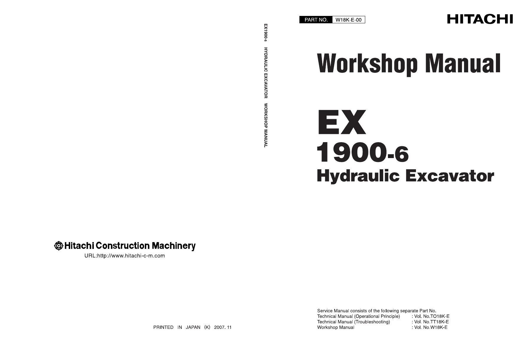
Hitachi EX1900-6 Hydraulic Excavator Workshop Manual – Complete Repair & Service Guide
Original price was: $39.95.$23.95Current price is: $23.95.
The complete Hitachi EX1900-6 Hydraulic Excavator Workshop Manual in PDF. 552 pages covering disassembly, assembly, maintenance standards, torque values, and repair procedures for the upperstructure, undercarriage, and front attachment.
Description
Hitachi EX1900-6 Hydraulic Excavator Workshop Manual
The Hitachi EX1900-6 Hydraulic Excavator Workshop Manual is the complete technical service publication for the EX1900-6 mining-class excavator. Published by Hitachi Construction Machinery, this workshop manual delivers the disassembly, assembly, maintenance, and repair procedures needed to keep the machine operating correctly. It covers the upperstructure, undercarriage, front attachment, hydraulic components, and their maintenance standards. This is the reference a technician turns to when a component needs to come apart, when a torque value matters, or when a wear limit has to be checked.
This Hitachi EX1900-6 workshop manual is structured for experienced technicians. Each component group provides step-by-step removal and installation sequences, disassembly and assembly procedures, maintenance standards with allowable limits, tightening torques, component weights, and special tool references. Whether you are pulling a swing device, resealing a boom cylinder, rebuilding a travel motor, or checking undercarriage wear, the relevant procedure is covered in this manual.
File Details
- Manual type: Workshop Manual
- Brand: Hitachi
- Model: EX1900-6
- Machine type: Hydraulic Excavator
- Language: English
- File format: PDF
- Page count: 552 pages
- Document revision: Information contained to 11 July 2008
- Publisher: Hitachi Construction Machinery Co., Ltd.
Chapters Covered
The manual is organized into four sections, each divided into focused groups:
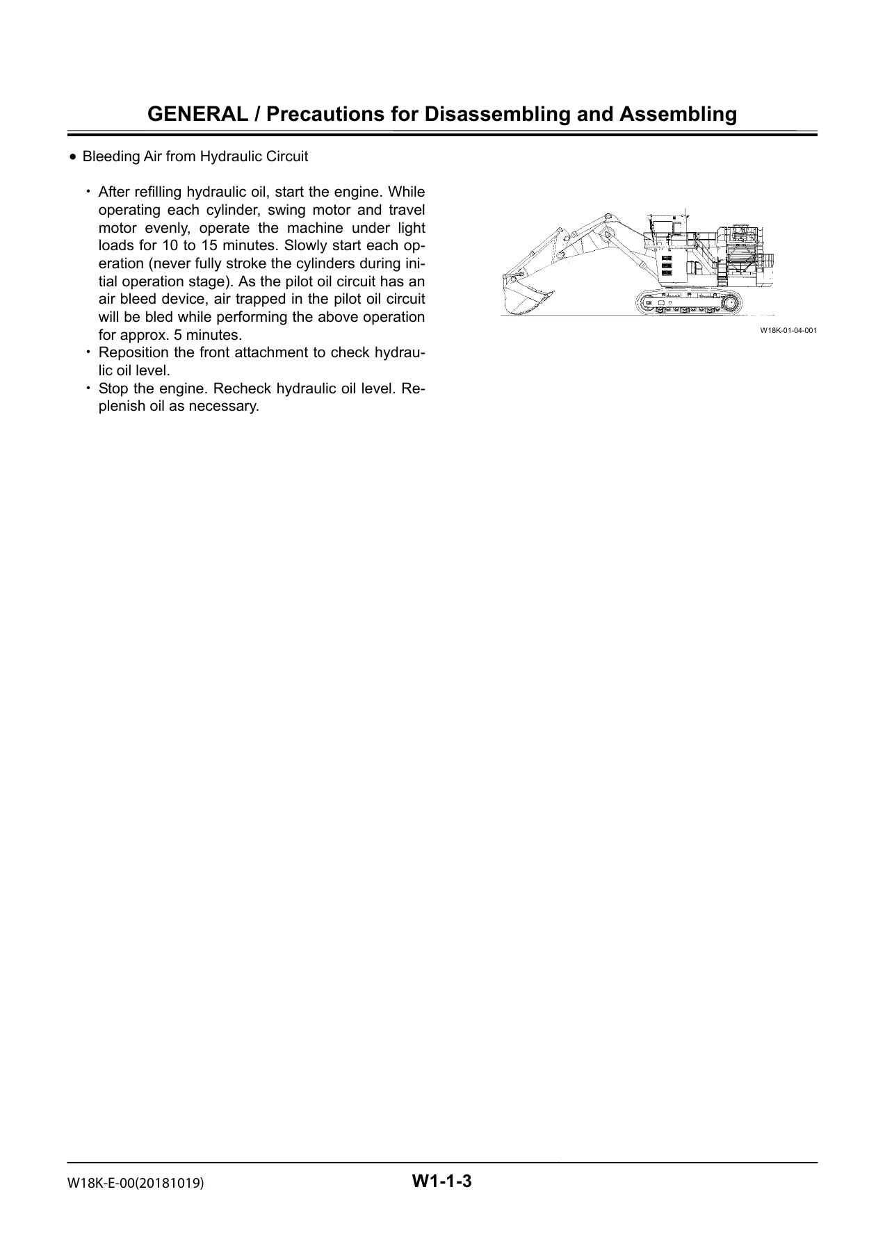
- Section 1 – General: Precautions for Disassembling and Assembling; Tightening (torque specification, torque chart, piping joints, periodic replacement of parts); Painting (painting specification, masking specification); Bleeding Air from Hydraulic Oil Tank.
- Section 2 – Upperstructure: Cab; Counterweight; Pump Device; Control Valve; Swing Device; DQR Valve; Shuttle Valve; EHC Valve; Oil Cooler Fan Motor; Compressor Drive Motor; Air Conditioner; Grease Pump.
- Section 3 – Undercarriage: Swing Bearing; Travel Device; Travel Brake Valve; Center Joint; Adjuster Cylinder; Front Idler; Upper and Lower Rollers; Track; Accumulator; Welding Repair Procedure.
- Section 4 – Front Attachment: Front Attachment; Cylinder; Bushing and Point.
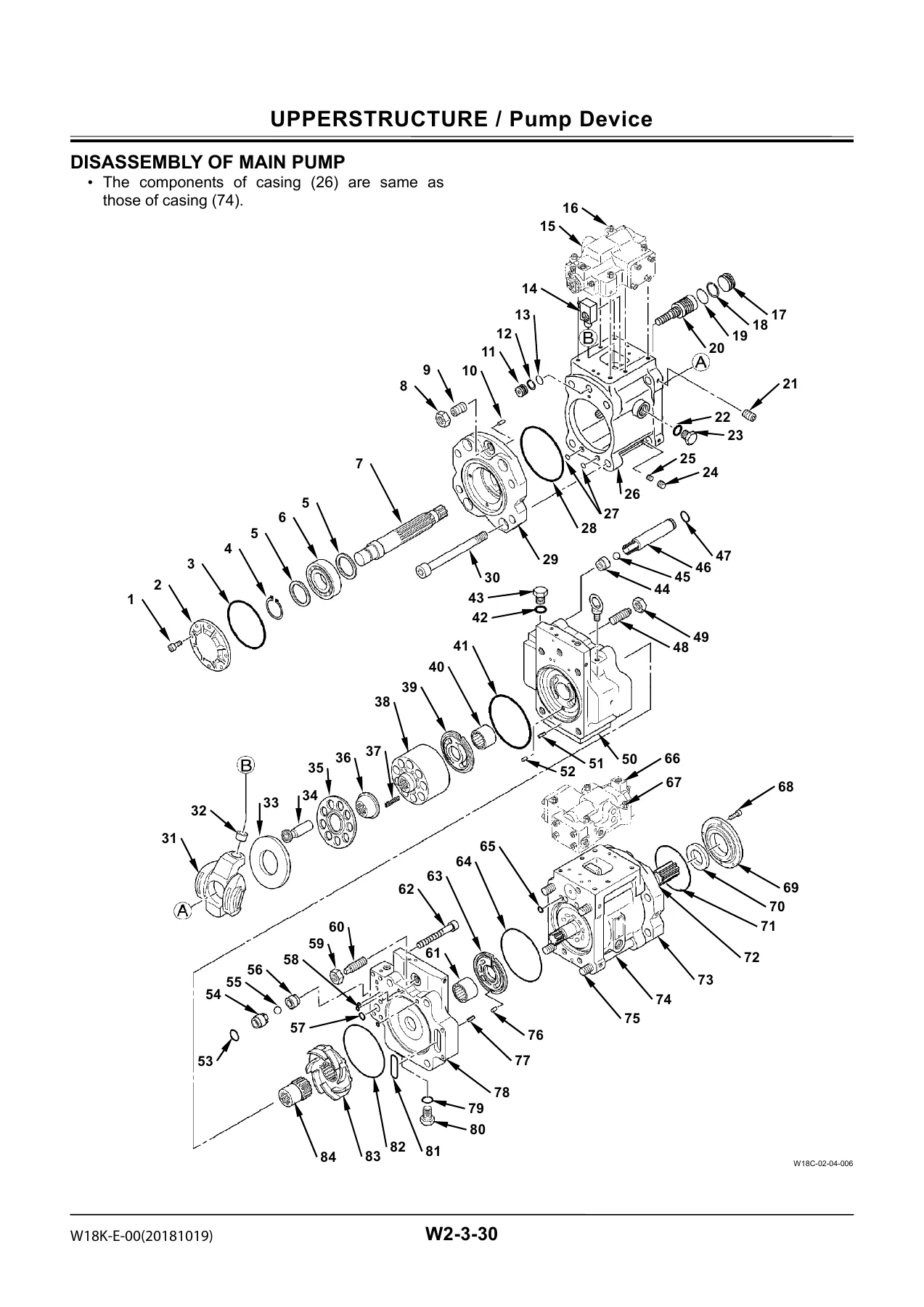
Within each group, the Hitachi EX1900-6 repair manual provides the actual procedures: removal and installation sequences with bolt sizes and wrench sizes, disassembly and assembly steps with matching-mark guidance, exploded component illustrations, maintenance standards with standard and allowable-limit dimensions, and complete tightening torque tables. The manual also includes a Technical Manual reference structure (Operational Principle and Troubleshooting), though this product is the Workshop Manual volume.
What This EX1900-6 Workshop Manual Covers
Upperstructure Service
Complete removal and installation of the cab, counterweight, pump device (including the pump transmission, main pump, regulator, oil cooler fan drive pump, air conditioner compressor drive pump, pilot pump, and pump transmission oil lubrication pump), control valve, swing device and swing motor, DQR valve, shuttle valve, EHC valve, oil cooler fan motor, compressor drive motor, and grease pump. Disassembly and assembly procedures include the maintenance standards and torque values required for each component.
Undercarriage Service
The undercarriage section covers the swing bearing, travel device (travel reduction gear, travel motor, and travel mode selection valve), travel brake valve, center joint, adjuster cylinder, front idler, upper and lower rollers, track, and accumulator. The welding repair procedure chapter provides detailed instructions for repairing the track shoe, front idler, and sprocket, including welding rod specifications, pre-heat temperatures, and post-weld inspection.
Front Attachment Service
Removal and installation of the complete front attachment for both loading shovel and backhoe configurations, plus the boom cylinder, arm cylinder, bucket cylinder, level cylinder (loading shovel), and dump cylinder (loading shovel). The cylinder chapter includes complete disassembly and assembly procedures with seal installation guidance, tightening torques, and the main points to bleed air from each cylinder circuit.
Component Weights & Lifting Data
The manual lists component weights throughout to help plan safe lifting operations. Examples include:
- Cab: 1210 kg (2668 lb)
- Counterweight: 25300 kg (55800 lb)
- Pump device: 1540 kg (3400 lb)
- Control valve: 260 kg (580 lb)
- Swing device: 1420 kg (3140 lb)
- Travel motor: 260 kg (580 lb)
- Travel reduction gear (sprocket side): 2800 kg (6180 lb)
- Track: 8640 kg (19100 lb)
- Swing bearing: 4190 kg (9240 lb)
- Boom assembly (loading shovel): 17800 kg (39300 lb)
- Boom assembly (backhoe): 22200 kg (49000 lb)
- Arm (loading shovel): 6700 kg (14800 lb)
- Arm (backhoe): 9700 kg (21400 lb)
Maintenance Standards & Service Limits
Every disassembly chapter includes a maintenance standard table listing the standard dimension, allowable limit, and remedy for worn components. These cover clearances between plungers and cylinder block bores, spring free lengths, shoe thicknesses, spherical bearing clearances, retainer-to-bushing distances, disc spring thicknesses, brake spring lengths, and separator/friction plate heights. The manual also includes track sag specifications (570 to 640 mm) and accumulator gas pressure specifications (9.8 MPa, 100 kgf/cm², 1420 psi at 20°C).
Tools & Procedures
Special tool references are called out throughout, including the ST 3931 bearing nut tool for travel devices, the ST 2646 oil seal installer for swing motors, the ST 7304/ST 7305 shaft alignment tools for pump installation, and the ST 6651 oil feed pump adapter. Matching marks, lock washer replacement, LOCTITE and THREEBOND application points, and O-ring replacement guidance are all specified in the procedures.
Why This Manual Matters
The Hitachi EX1900-6 Hydraulic Excavator Workshop Manual gives you the correct procedures, the right torque values, and the service limits that prevent comebacks and component damage. Whether you are rebuilding a travel motor, resealing a cylinder, replacing a swing bearing, or adjusting track tension, the manual provides the exact sequence and specification. It is the difference between guessing and knowing.
IMAGES PREVIEW
Instant PDF Delivery
This Hitachi EX1900-6 Workshop Manual is delivered as an instant PDF download after payment. No shipping, no waiting. The file works on any device — laptop, tablet, or phone — and can be printed for use in the shop. Keep it on hand for every repair and maintenance job on your EX1900-6.

Reviews
There are no reviews yet.