Hitachi Ex200 Service Manual – PDF DOWNLOAD
Original price was: $59.95.$29.95Current price is: $29.95.
Hitachi Ex200 Service Manual
Description
Hitachi Ex200 Service Manual
FILE DETAILS:
LANGUAGE:ENGLISH
PAGES:1031
DOWNLOADABLE:YES
FILE TYPE:PDF
HITACHI EX200 SERVICE MANUAL – PDF DOWNLOAD:
IMAGES PREVIEW OF THE MANUAL:
DESCRIPTION:
Hitachi Ex200 Service Manual
1. SAFETY ALERT SYMBOL AND HEADLINE OF NOTATION
In this manual, the following safety alert symbol and the headline of notation are used to arouse importance in safety and technology.
1.1 SAFETY ALERT SYMBOL
This is the safety alert symbol. When you see this symbol, be alert to the potential for personal injury. Never fail to follow the safety instructions prescribed along with the safety alert symbol.
1.2 HEADLINE OF NOTATION .
‘ The word “NOTE” is headlined to supplement an additional technical information or know-how.
2. T0 UPDATE THE CONTENTS OF THE SERVICE MANUAL
The each service manual is serially numbered and its number is recorded by us with the name of the person who received the service manual. And they are referred when the delivered service manuals are required to be revised by upato-date information as such information must be supplied quickly and correctly. Please, advise us the name of person who keeps the service manual and is in responsible to keep it up-to—date by sending back to us the slip of the shipping information sheet enclosed in the service manual.
‘ In case that the personal administration change is made, please inform us of the name of the person who is newly appointed to maintain the serivce manual.
3. TO KEEP CONFIDENTIAL
Please, keep the technical informations and know-how contained in the sen/ice manual confidential to the outsiders.
TABLE OF CONTENTS:
Hitachi Ex200 Service Manual
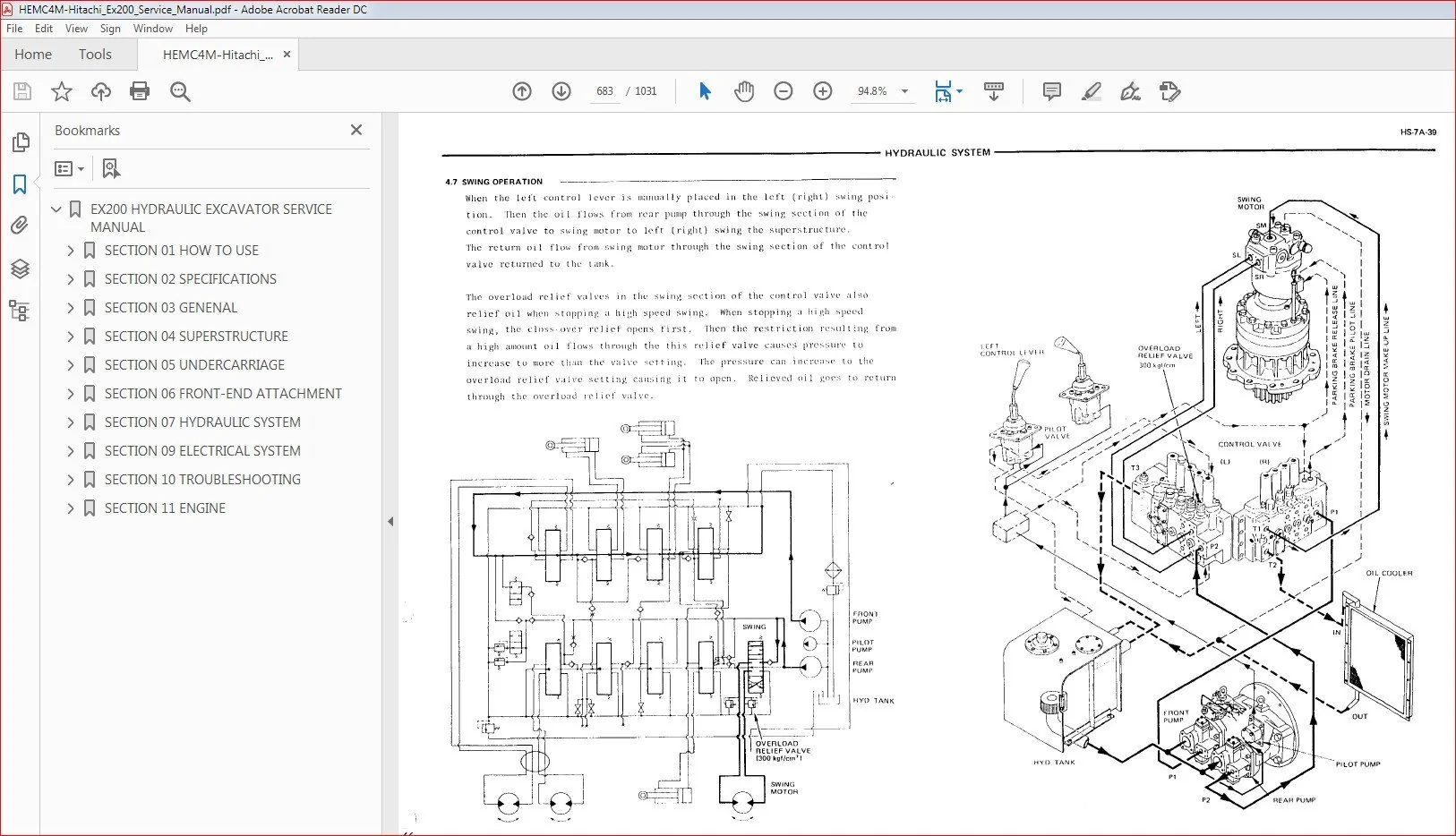
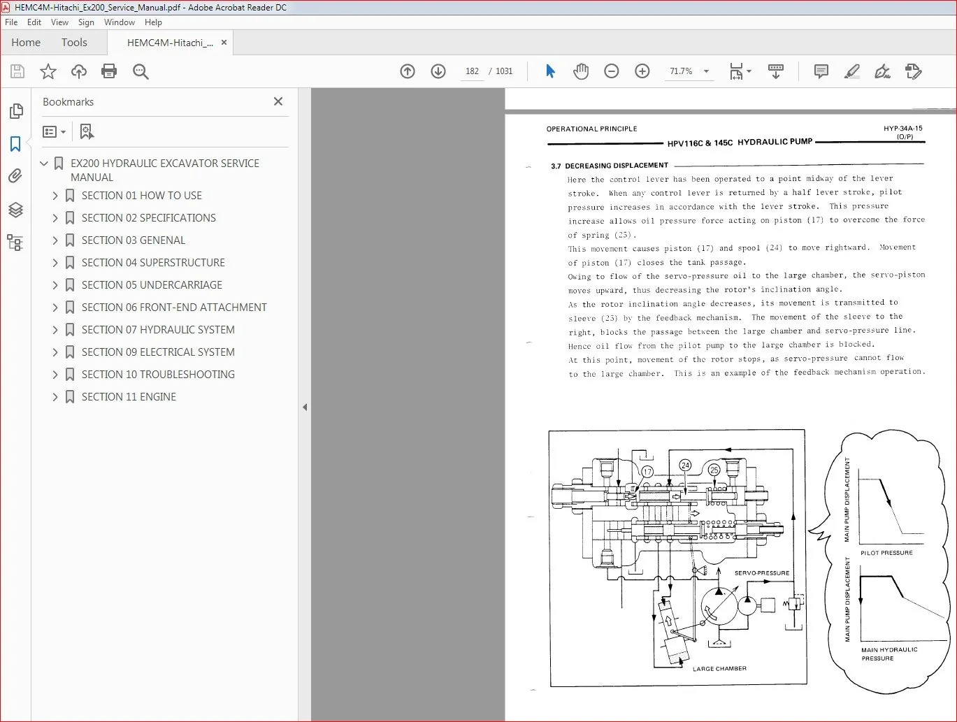
EX200 HYDRAULIC EXCAVATOR SERVICE MANUAL.....................................................................   0
	SECTION 01 HOW TO USE....................................................................................   1
		Group 01 Section & Group Contents....................................................................   2
		Group 02 Introduction................................................................................   5
			Introduction ....................................................................................   5
			Care of the Handling.............................................................................   5
		Group 03 Features of This Manual.....................................................................   6
			Construction.....................................................................................   6
			Tab .............................................................................................   7
			Page.............................................................................................   7
			Contents.........................................................................................   7
		Group 04 Safty Informations .........................................................................   8
	SECTION 02 SPECIFICATIONS................................................................................  11
		Group 01 General Specifications......................................................................  13
			Dimensions.......................................................................................  13
			Weights and Ground Pressure......................................................................  14
			Capability.......................................................................................  14
			Backhoe Buckets..................................................................................  14
			Other Attachments................................................................................  14
			Working Ranges...................................................................................  15
			Lifting Capacities...............................................................................  16
		Group 02 Components Specifications...................................................................  18
			Engine...........................................................................................  18
			Main Pump........................................................................................  22
			Pilot Pump ......................................................................................  23
			Control Valve....................................................................................  24
			Swing Motor......................................................................................  24
			Travel Motor ....................................................................................  25
			Center Joint.....................................................................................  25
			Pilot Valve (for Travel).........................................................................  25
			Pilot Valve (for Swing,Boom,Arm,Bucket)..........................................................  26
			Control Neutralizer Valve........................................................................  26
			Shockless Valve..................................................................................  26
			Accumulator......................................................................................  26
			Hydraulic Tank...................................................................................  26
			Suction Filter...................................................................................  27
			Full-Flow Filter.................................................................................  27
			Air Breezer......................................................................................  27
			Bypass Check Valve...............................................................................  27
			Pilot Filter.....................................................................................  27
			Oil Cooler.......................................................................................  27
			Restriction Valve................................................................................  27
			Solenoid Valve...................................................................................  28
			Mode Selection Cylinder..........................................................................  28
			Boom Cylinder....................................................................................  28
			Arm Cylinder.....................................................................................  28
			Bucket Cylinder..................................................................................  28
		Group 03 Torque Reference............................................................................  29
		Group 04 Others......................................................................................  34
			maintenance Intervals............................................................................  34
		Group 05 Conversion Table............................................................................  36
	SECTION 03 GENENAL.......................................................................................  42
		Group 01 Introduction................................................................................  43
			 Introduction....................................................................................  43
		Group 02 Construction................................................................................  44
			Construction.....................................................................................  44
		Group 03 Hydraulic System............................................................................  47
			Hydraulic System.................................................................................  47
			Main Hydraulic Circuit...........................................................................  48
			Pilot Hydraulic Circuit..........................................................................  52
		Group 04 Electric System.............................................................................  56
			Main Circuit.....................................................................................  56
			Control System...................................................................................  57
			Monitor System...................................................................................  57
		Group 05 Maintenance.................................................................................  58
			Removal and Instrallation (Cab,Front Attachment,Superstructure) .................................  58
			Maintenance......................................................................................  71
			Name Plate.......................................................................................  87
	SECTION 04 SUPERSTRUCTURE................................................................................  90
		Group 01 Superstructure..............................................................................  92
			Main Frame and Counter-Weight....................................................................  92
			Engine...........................................................................................  94
			Hydraulic Oil Tank............................................................................... 107
			Fuel Tank........................................................................................ 111
			Swing Device..................................................................................... 113
			Electric Parts................................................................................... 118
			Cab Heater....................................................................................... 121
			Engine Control Lever............................................................................. 123
			Main Piping ..................................................................................... 124
			Oil Cooler Piping................................................................................ 126
			Cover............................................................................................ 131
			Pump Device...................................................................................... 135
			Control Box...................................................................................... 142
			Cab Group........................................................................................ 150
			Pilot Piping..................................................................................... 157
			Control Lever.................................................................................... 164
		Group 02 Hydraulic Pump Device....................................................................... 168
			O/P, Hydraulic Pump.............................................................................. 168
				Outline...................................................................................... 168
				Function..................................................................................... 170
				Operation.................................................................................... 175
			D/A, Main Pump .................................................................................. 189
				Disassembry.................................................................................. 189
				Inspection................................................................................... 195
				Assembly..................................................................................... 198
				Special Tools................................................................................ 207
				Parts List................................................................................... 209
			D/A,RH23A.25B.26A.28A Regulator.................................................................. 211
				Disassembly.................................................................................. 211
				Assembly..................................................................................... 217
				Special Tool................................................................................. 222
				Parts List................................................................................... 223
			D/A,Pump Transmission............................................................................ 225
				Disassembly.................................................................................. 225
				Inspection................................................................................... 230
				Assembly..................................................................................... 231
				Special Tool................................................................................. 236
				Parts List................................................................................... 236
			D/A.HY-ZFS Gear Pump............................................................................. 238
				Disassembly.................................................................................. 238
				Inspection................................................................................... 241
				Assembly..................................................................................... 243
				Special Tool................................................................................. 245
		Group 03 Control Valve............................................................................... 247
			O/P, KVMG-270-HC Control Valve................................................................... 247
				General...................................................................................... 247
				Construction and Function.................................................................... 251
			D/A, O/P, KVMG-270-HC Control Valve.............................................................. 267
				Dissasembly.................................................................................. 267
				Inspection................................................................................... 281
				Assembly..................................................................................... 282
		Group 04 Swing Device................................................................................ 303
			O/P, MX173 Cab Swing Motor ...................................................................... 303
				Outline...................................................................................... 303
				Function..................................................................................... 305
			D/A, O/P, MX173 Cab Swing Motor ................................................................. 312
				Disassembly.................................................................................. 312
				Inspection................................................................................... 321
				Assembly..................................................................................... 323
				Special Tools................................................................................ 333
			O/P.M2X170.210 Cab Motor......................................................................... 337
				Outline...................................................................................... 337
				Function..................................................................................... 339
			D/A.M2X170.210 Cab Motor......................................................................... 346
				Disassembly.................................................................................. 346
				Inspection................................................................................... 351
				Assembly..................................................................................... 353
			D/A, Swing Reduction Device...................................................................... 364
				Disassembly.................................................................................. 364
				Assembly..................................................................................... 369
				Special Tools................................................................................ 375
		Group 05 Pilot Valve................................................................................. 378
			O/P, Pilot Valve................................................................................. 378
				Outline...................................................................................... 378
				Function..................................................................................... 380
			D/A, HV Type Pilot Valve (Front-End Attachment) ................................................. 385
				Disassembly.................................................................................. 385
				Assembly..................................................................................... 391
				Special Tools................................................................................ 397
			D/A, HV Type Pilot Valve (Travel)................................................................ 399
				Disassembly.................................................................................. 399
				Assembly..................................................................................... 405
				Special Tools................................................................................ 411
		Group 06 Control Neutralizer Valve................................................................... 413
			O/P, Control Neutralizer Valve .................................................................. 413
				Outline...................................................................................... 413
			D/A, Control Neutralizer Valve................................................................... 415
				Disassembly.................................................................................. 415
				Assembly..................................................................................... 417
		Group 07 Shockless Valve............................................................................. 420
			O/P, Shockless Valve............................................................................. 420
				Outline...................................................................................... 420
				Function..................................................................................... 421
			D/A, Shockless Valve............................................................................. 425
				Disassembly.................................................................................. 425
				Inspection................................................................................... 428
				Assembly..................................................................................... 429
		Group 08 Accumulator................................................................................. 434
			O/P, Accumulator................................................................................. 434
				Outline...................................................................................... 434
				Function..................................................................................... 435
		Group 09 Solenoid Valve.............................................................................. 436
			O/P,  Solenoid Valve............................................................................. 436
				Outline...................................................................................... 436
				Function..................................................................................... 437
			D/A,  Solenoid Valve............................................................................. 441
				Disassembly.................................................................................. 441
				Inspection................................................................................... 445
				Assembly..................................................................................... 446
		Group 10 Mode Selection Cylinder..................................................................... 451
			D/A, Mode Selection Cylinder..................................................................... 451
				Disassembly.................................................................................. 451
				Assembly..................................................................................... 452
	SECTION 05 UNDERCARRIAGE................................................................................. 455
		Group 01 Undercarriage............................................................................... 456
			Track Frame...................................................................................... 456
			Swing Bearing ................................................................................... 458
			Travrl Device and Piping......................................................................... 465
			Front  Idler..................................................................................... 475
			Adjuster......................................................................................... 482
			Upper Roller and Lower Roller.................................................................... 494
			Track Link....................................................................................... 508
			Center Joint..................................................................................... 518
		Group 02 Travel Devece............................................................................... 525
			O/P, Travel Motor................................................................................ 525
				Outline...................................................................................... 525
				Travel....................................................................................... 525
				Brake Valve Assembly......................................................................... 529
			D/A, Travel Motor and Travel Device.............................................................. 532
				Disassemble Travel Motor..................................................................... 532
				Inspect Travel Motor......................................................................... 539
				Assemble Travel Motor........................................................................ 541
				Special Tools................................................................................ 551
			D/A, Travel Motor and Travel Divice.............................................................. 570
				Disassemble.................................................................................. 570
				Assemble..................................................................................... 577
				Special Tools................................................................................ 587
		Group 03 Center Joint................................................................................ 592
			O/P, Center Joint................................................................................ 592
				Outline...................................................................................... 592
			D/A, Center Joint ............................................................................... 593
				Disassembly.................................................................................. 593
				Assembly..................................................................................... 596
				Special Tools................................................................................ 599
	SECTION 06 FRONT-END ATTACHMENT ......................................................................... 601
		Group 01 FRONT-END ATTACHMENT ....................................................................... 602
			Boom Assembly.................................................................................... 602
			Arm  Assembly.................................................................................... 604
			Bucket  Assembly................................................................................. 607
			Front Pipings.................................................................................... 620
		Group 02 Hydraulic Cylinder.......................................................................... 635
			Operational Principle............................................................................ 634
			Disassembly and  Assembly........................................................................ 635
		Group 03 Pin and Bushing............................................................................. 647
			Specifications................................................................................... 647
		Group 04 Point and Side Cutter....................................................................... 649
			Maintenance...................................................................................... 649
	SECTION 07 HYDRAULIC SYSTEM.............................................................................. 651
		Group 01 Outline..................................................................................... 653
			Outline.......................................................................................... 653
		Group 02 Main Hydraulic Circuit...................................................................... 654
			Suction Circuit and Delivery Circuit............................................................. 654
			Return Circuit................................................................................... 658
			Drain Circuit.................................................................................... 660
		Group 03 Pilot Circuit............................................................................... 663
			Suction,Delivery and Return Circuit.............................................................. 664
			Accumulator...................................................................................... 666
			Control Neutralizer Valve........................................................................ 666
			Pump Displacement Control Circuit................................................................ 668
			Relief pressure Change Circuit .................................................................. 671
			Switch Valve Circuit............................................................................. 671
			Heat-Run Circuit................................................................................. 672
			Swing Parking Brake ............................................................................. 674
		Group 04 Single Operation............................................................................ 676
			Boom Raise Circuit Operation..................................................................... 676
			Boom Lower Circuit Operation .................................................................... 677
			Arm Roll-In Circuit Operation.................................................................... 678
			ArmRoll-Out Circuit Operation.................................................................... 679
			Bucket Circuit Operation......................................................................... 680
			Swing Circuit Operation.......................................................................... 681
			Swing Operation.................................................................................. 683
			Travel Circuit Operation......................................................................... 684
			Travel Forward and Reverse Operation............................................................. 685
		Group 05 Combined Operation.......................................................................... 686
			Outline.......................................................................................... 686
			Combined Swing and Boom Operation................................................................ 687
			Combined Swing and Arm Operation................................................................. 688
			Combined Swing and Bucket Operation.............................................................. 689
			Combined Swing, Boom, Arm and Buket Operation.................................................... 690
			Combined Swing and Travel Operation.............................................................. 691
			Combined Boom and Travel Operation .............................................................. 692
			Combined Arm and Travel Operation ............................................................... 693
			Combined Bucket and Travel Operation ............................................................ 694
		Group 06 Extra Control Circuit....................................................................... 695
			Outline ......................................................................................... 695
			Single Operation................................................................................. 697
			Combined Extra and Arm Roll-In Operation......................................................... 698
			Combined Extra and Arm Roll-Out Operation........................................................ 699
	SECTION 09 ELECTRICAL SYSTEM............................................................................. 700
		Group 01 Safety Precautions.......................................................................... 701
			Safety Precautions............................................................................... 701
		Group 02 Specifications ............................................................................. 702
			Battery, Starter, Safety, Relay, Alternator, Regulator, Headlight, Wiper Motor, Speaker, Fuse.... 702
		Group 03 Construction and Function................................................................... 704
			Construction of Electrical System................................................................ 704
			Monitor.......................................................................................... 706
			Control (E-P Control) System..................................................................... 715
			Function of Seneors and Relays................................................................... 724
		Group 04 Circuit Operations.......................................................................... 729
			Characteristics of Electrical Circuit............................................................ 729
			Electrical Circuit............................................................................... 730
			Battery Circuit.................................................................................. 731
			Preheat Circuit.................................................................................. 732
			Starting Circuit................................................................................. 733
			Charging Circuit................................................................................. 735
			Safety Circuit................................................................................... 739
			Accessory Circuit................................................................................ 740
			Gauge Panel Circuit.............................................................................. 741
			Control Circuit.................................................................................. 742
		Group 05 Maintenance................................................................................. 743
			Gauge Panel ..................................................................................... 743
			Assembly and Adjustment of Auto-idle Device...................................................... 751
	SECTION 10 TROUBLESHOOTING............................................................................... 753
		Group 01 Introduction................................................................................ 755
			General Infomation............................................................................... 755
			Notes on Performance Measurement................................................................. 757
		Group 02 Diagnose Malfunctions....................................................................... 760
			Malfunctions Phenomena........................................................................... 760
			Hydraulic System................................................................................. 762
			Electric System.................................................................................. 776
		Group 03 Excavator Performance Test.................................................................. 806
			introduction..................................................................................... 806
			Engine Performance Measurement................................................................... 806
			Travel Performance Measurement................................................................... 809
			Swing Performance Measurement.................................................................... 815
			Front-end Attachment............................................................................. 819
			Control Lever Performance Measurement............................................................ 823
		Group 04 Components Performance Standard............................................................. 827
			introduction..................................................................................... 827
			Pilot Relief Valve............................................................................... 827
			Main Relief Valve................................................................................ 829
			Overload Relief Valve............................................................................ 832
			Swing Crossover Relief Valve..................................................................... 834
			Travel Crossover Relief Valve.................................................................... 835
			Main Hydraulic Pump.............................................................................. 837
			Travel Motor..................................................................................... 844
			Swing Motor...................................................................................... 845
		Group 05 Electrical System Test...................................................................... 847
			Common Circuit Test.............................................................................. 847
			Articles Necessary For Electrical Circuit Test................................................... 849
			Measurement Procedures........................................................................... 850
			Mesurement Standard.............................................................................. 851
	SECTION 11 ENGINE........................................................................................ 860
		Group 01 General Information......................................................................... 863
			General Repair Instructions...................................................................... 863
			Notes on the Format of this Manual............................................................... 863
			Main Data and Specifications..................................................................... 867
			Design Features and General Outline.............................................................. 871
			Tightening Torque Specifications................................................................. 874
			Anglular Nut and Bolt Tightening Method.......................................................... 875
			Major Parts Fixing Nuts and Bolts................................................................ 877
			Identifications.................................................................................. 888
		Group 02 Maintenance................................................................................. 889
			Lubricating System............................................................................... 889
			Fuel System...................................................................................... 890
			Cooling System................................................................................... 894
			Valve Clearance Adjustment....................................................................... 894
			Injection Timing................................................................................. 896
			Compression Pressure Measurement................................................................. 902
			Turbocharger Inspection.......................................................................... 903
			Engine Repair Kit................................................................................ 904
			Recommended Lubricants........................................................................... 906
			Engine Oil Viscosity Chart....................................................................... 906
		Group 03 Engine Disassembly.......................................................................... 907
			External Parts................................................................................... 907
			Major Components................................................................................. 915
			Rocker Arm and Rocker Arm Shaft.................................................................. 917
			Cylinder Head.................................................................................... 918
			Piston and Connection Rod........................................................................ 919
		Group 04 Inspection and Repair....................................................................... 921
			Cylinder Head.................................................................................... 921
			Valve Guide...................................................................................... 922
			Valve Spring..................................................................................... 925
			Tappet........................................................................................... 926
			Push Rod......................................................................................... 927
			Rocker Arm Shaft and Rocker Arm.................................................................. 927
			Idler Gear and Idler Gear Shaft.................................................................. 928
			Cam Shaft........................................................................................ 929
			Cylinder Body and Liner.......................................................................... 930
			Piston and Piston Ring........................................................................... 935
			Piston Pin....................................................................................... 936
			Connecting Rod................................................................................... 937
			Crank Shaft...................................................................................... 939
			Fly Wheel and Fly Wheel Housing.................................................................. 947
			Timing Gear Case Cover........................................................................... 948
		Group 05 Engine Assembly............................................................................. 949
			Piston and Connecting Rod........................................................................ 949
			Cylinder Head.................................................................................... 951
			Rocker Arm and Rocker Arm Shaft.................................................................. 955
			Major Components................................................................................. 956
			External Parts................................................................................... 966
			Engine Tuning Operation.......................................................................... 973
			Engine Section View.............................................................................. 975
		Group 06 Lubricating System.......................................................................... 976
			General Description.............................................................................. 976
			Oil Pump......................................................................................... 977
			Main Oil Filter.................................................................................. 979
			Oil Cooler....................................................................................... 981
		Group 07 Cooling System.............................................................................. 983
			General Description.............................................................................. 983
			Water Pump....................................................................................... 984
			Thermostat....................................................................................... 989
		Group 08 Fuel System................................................................................. 990
			General Descrintion.............................................................................. 990
			Fuel Filter...................................................................................... 991
			Injection Nozzle................................................................................. 993
		Group 09 Turbo Charger............................................................................... 998
			General Description.............................................................................. 998
			Identification................................................................................... 999
			Roter Shaft Play Inspection......................................................................1000
		Group 10 Engine Electricals..........................................................................1001
			Starter Motor....................................................................................1001
			Alternator.......................................................................................1004
		Group 11 Troubleshooting.............................................................................1008
			Hard Staeting....................................................................................1008
			Unstable Low Idring..............................................................................1012
			Insufficient Power...............................................................................1015
			Excessive Fuel Consumption.......................................................................1018
			Overheating......................................................................................1021
			White Exhaust Smoke..............................................................................1023
			Darkish Exhaust Smoke............................................................................1024
			Not Rising Oil Pressure..........................................................................1025
			Abnormal Engine Noise............................................................................1027
		Group 12 Special Tool List...........................................................................1030
			Special Tool List................................................................................1030
PLEASE NOTE:
- This is the SAME exact manual used by your dealers to fix your vehicle.
- The same can be yours in the next 2-3 mins as you will be directed to the download page immediately after paying for the manual.
- Any queries / doubts regarding your purchase, please feel free to contact [email protected]

Sincere Jedidiah –