Hitachi Ex3600-6 Hydraulic Excavator Technical Workshop Manual (W18M-E-00) – PDF Download
Original price was: $67.95.$26.95Current price is: $26.95.
- Hitachi Ex3600-6 Hydraulic Excavator Technical Workshop Manual
- Part No:W18M-E-00
Description
Hitachi Ex3600-6 Hydraulic Excavator Technical Workshop Manual (W18M-E-00)
File Details:
Hitachi Ex3600-6 Hydraulic Excavator Technical Workshop Manual (W18M-E-00)
- Manual Language:English
- Pages: 514
- Size: 11.7 MB
- Downloadable:Yes
- Format:PDF
HITACHI EX3600-6 HYDRAULIC EXCAVATOR TECHNICAL WORKSHOP MANUAL (W18M-E-00) – PDF DOWNLOAD:
Image Preview:
Description:
Hitachi Ex3600-6 Hydraulic Excavator Technical Workshop Manual (W18M-E-00)
TO THE READER
• This manual is written for an experienced technician to provide technical information needed to maintain and repair this machine.
• Be sure to thoroughly read this manual for correct product information and service procedures.
• If you have any questions or comments, at if you found any errors regarding the contents of this manual, please contact using “Service Manual Revision Request Form at the end of this manual.
ADDITIONAL REFERENCES
• Please refer to the materials listed below in addition to this manual.
• The Operator’s Manual
• The Parts Catalog
• Operation Manual of the Engine
• Parts Catalog of the Engine
• Hitachi Training Material
MANUAL COMPOSITION
• This manual consists of three portions: the Technical Manual (Operational Principle), the Technical Manual (Troubleshooting) and the Workshop Manual.
• Information included in the Technical Manual (Operational Principle): technical information needed for redeliver and delivery, operation and activation of all devices and systems.
• Information included in the Technical Manual (Troubleshooting): technical information needed for operational performance tests, and troubleshooting procedures.
• Information included in the Workshop Manual: technical information needed for maintenance and repair of the machine, tools and devices needed for maintenance and repair, maintenance standards, and removal/installation and assemble/ disassemble procedures.
Table of Contents:
Hitachi Ex3600-6 Hydraulic Excavator Technical Workshop Manual (W18M-E-00)
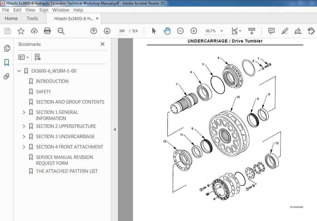
EX3600-6_W18M-E-00...................................................................................  1
	INTRODUCTION.....................................................................................  3
	SAFETY...........................................................................................  5
	SECTION AND GROUP CONTENTS....................................................................... 35
	SECTION 1 GENERAL INFORMATION.................................................................... 37
		Group 1 Precautions for Disassembling and Assembling......................................... 39
			Precautions for Disassembling and Assembling............................................. 39
		Group 2 Tightening Torque.................................................................... 47
			Tightening Torque Specification.......................................................... 47
			Torque Chart............................................................................. 49
			Piping Joint............................................................................. 52
			Periodic Replacement of Parts............................................................ 56
		Group 3 Painting............................................................................. 57
			Painting................................................................................. 57
		Group 4 Bleeding Air from Hydraulic Oil
Tank................................................ 61
			Bleeding Air from Hydraulic Oil Tank..................................................... 61
	SECTION 2 UPPERSTRUCTURE......................................................................... 65
		Group 1 Cab.................................................................................. 67
			Remove and Install Cab................................................................... 67
			Dimensions of the Cab Glass.............................................................. 70
		Group 2 Counterweight........................................................................ 77
			Remove and Install Counterweight......................................................... 77
			Remove and Install Pump Device........................................................... 81
		Group 3 Pump Device.......................................................................... 81
			Remove and Install Pump Device........................................................... 81
			Disassemble Pump Transmission............................................................100
			Assemble Pump Transmission...............................................................104
			Disassemble Main Pump....................................................................108
			Assemble Main Pump.......................................................................114
			Maintenance Standard.....................................................................118
			Disassemble Regulator (Main Pump)........................................................120
			Assemble Regulator (Main Pump)...........................................................126
			Disassemble Fan Motor Drive Pump.........................................................132
			Assemble Fan Motor Drive Pump............................................................138
			Maintenance Standard.....................................................................142
			Disassemble Regulator
 (Fan Motor Drive)................................................144
			Assemble Regulator (Fan Motor Drive).....................................................150
			Structure of Pilot Pump..................................................................156
			Structure of  Pump Transmission
Oil Lubrication Pump and
 Air Compressor Drive Pump....158
		Group 4 Control Valve........................................................................161
			Remove and Install Control Valve.........................................................161
			Disassemble Control Valve................................................................166
			Assemble Control Valve...................................................................174
		Group 5 Swing Device.........................................................................181
			Remove and Install Swing Device..........................................................181
			Disassemble Swing Device.................................................................184
			Assemble Swing Device....................................................................192
			Disassemble Swing Motor..................................................................200
			Assemble Swing Motor.....................................................................204
			Maintenance Standard.....................................................................208
			Disassemble and
 Assemble Valve Unit....................................................210
		Group 6 D.Q.R Valve..........................................................................213
			Remove and Install D.Q.R Valve...........................................................213
			Structure of  D.Q.R Valve................................................................218
		Group 7 Shuttle Valve........................................................................221
			Remove and Install Shuttle Valve.........................................................221
			Structure of Shuttle Valve...............................................................224
		Group 8 8-Spool Solenoid Valve...............................................................225
			Remove and Install
 8-Spool Solenoid Valve Unit.........................................225
			Structure of
 8-Spool Solenoid Valve Unit...............................................231
			Disassemble and Assemble
Proportional Solenoid Valve...................................232
			Structure of Solenoid....................................................................234
		Group 9 Oil Cooler Fan Motor.................................................................235
			Remove and Install
 Oil Cooler Fan Motor................................................235
			Disassemble Oil Cooler Fan Motor.........................................................240
			Assemble Oil Cooler Fan Motor............................................................242
			Maintenance Standard.....................................................................244
		Group 10 Radiator Fan Motor..................................................................245
			Remove and Install
Radiator Fan Motor...................................................245
			Structure of Radiator Fan Motor..........................................................258
		Group 11 Compressor Drive Motor..............................................................261
			Remove and Install
Compressor Drive Motor...............................................261
			Disassemble
 Compressor Drive Motor.....................................................264
			Assemble Compressor Drive Motor..........................................................266
		Group 12 Air Conditioner.....................................................................269
			Work after Replacing Components..........................................................269
			Add Compressor Oil.......................................................................269
			Charge Air Conditioner with
Refrigerant................................................270
		Group 13 Lift Cylinder
(Fast-Filling/Draining Device)......................................279
			Remove and Install Lift Cylinder.........................................................279
			Disassemble Lift Cylinder................................................................284
			Assemble Lift Cylinder...................................................................286
		Group 14 Lift Cylinder (Sliding Fold-In Ladder)..............................................289
			Remove and Install Lift Cylinder.........................................................289
			Disassemble Lift Cylinder................................................................296
			Assemble Lift Cylinder...................................................................298
	SECTION 3 UNDERCARRIAGE..........................................................................303
		Group 1 Swing Bearing........................................................................305
			Remove and Install Swing Bearing.........................................................305
		Group 2 Travel Device........................................................................307
			Remove and Install Travel Device.........................................................307
			Disassemble Travel Device................................................................312
			Assemble Travel Device...................................................................318
			Disassemble Travel Motor.................................................................322
			Assemble Travel Motor....................................................................328
			Maintenance Standard.....................................................................332
		Group 3 Travel Brake Valve...................................................................335
			Remove and Install Travel Brake Valve....................................................335
			Disassemble and Assemble Travel Brake Valve..............................................338
			Assemble Travel Brake Valve..............................................................340
		Group 4 Drive Tumbler........................................................................343
			Remove Drive Tumbler.....................................................................343
			Install Drive Tumbler....................................................................348
			Maintenance Standard.....................................................................358
		Group 5 Center Joint.........................................................................359
			Remove and Install Center Joint..........................................................359
			Disassemble Center Joint.................................................................364
			Assemble Center Joint....................................................................366
		Group 6 Adjuster Cylinder....................................................................369
			Remove and Install Adjuster Cylinder.....................................................369
			Disassemble Adjuster Cylinder............................................................372
			Assemble Adjuster Cylinder...............................................................374
		Group 7 Front Idler..........................................................................379
			Remove and Install Front Idler...........................................................379
			Disassemble Front Idler..................................................................382
			Assemble Front Idler.....................................................................384
			Maintenance Standard.....................................................................386
		Group 8 Upper and Lower Roller...............................................................387
			Remove and Install Upper/ Lower Rollers..................................................387
			Disassemble Upper Roller.................................................................392
			Assemble Upper Roller....................................................................394
			Disassemble Lower Roller.................................................................396
			Assemble Lower Roller....................................................................398
			Maintenance Standard.....................................................................400
		Group 9 Track................................................................................403
			Remove and Install Track.................................................................403
			Disassemble and Assemble Track...........................................................407
			Maintenance Standard.....................................................................408
		Group 10 Accumulator.........................................................................409
			Remove and Install Accumulator...........................................................409
			Disassemble Accumulator..................................................................412
			Assemble Accumulator.....................................................................414
		Group 11 Welding Repair Procedure............................................................419
			Welding Repair Procedure.................................................................419
			Welding Rod Specification................................................................420
	SECTION 4 FRONT ATTACHMENT.......................................................................429
		Group 1 Front Attachment.....................................................................431
			Remove and Install Front Attachment......................................................431
			Remove and Install Bucket and Arm (Loading Shovel))......................................432
			Remove and Install Bucket and Arm (Backhoe)..............................................440
			Remove and Install Boom (Backhoe and Loading Shovel))....................................448
		Group 2 Cylinder.............................................................................455
			Remove and Install Cylinder..............................................................455
			Disassemble Cylinder.....................................................................482
			Assemble Cylinder........................................................................490
			Main Points to Bleed Air.................................................................498
			Maintenance Standard.....................................................................500
		Group 3 Bushing and Point....................................................................503
			Remove and Install Bushing...............................................................503
			Maintenance Standard.....................................................................506
	SERVICE MANUAL REVISION REQUEST FORM.............................................................513
	THE ATTACHED PATTERN LIST........................................................................514
Please Note:
⦁ This is the SAME manual used by the dealers to troubleshoot any faults in your vehicle. This can be yours in 2 minutes after the payment is made.
⦁ Contact us at [email protected] should you have any queries before your purchase or that you need any other service / repair / parts operators manual.


Reid –
Great product