
Hitachi EX400-5 Excavator Workshop Manual – EX450H-5 Repair & Service PDF
Original price was: $39.95.$24.95Current price is: $24.95.
The Hitachi EX400-5 Excavator Workshop Manual covers EX400-5, EX450H-5, EX450LC-5, and EX450LCH-5 models. This PDF repair guide includes removal, installation, disassembly, assembly, and maintenance standards for the upperstructure, undercarriage, and front attachment — with tightening torques, special tools, and allowable limits throughout.
Description
The Hitachi EX400-5 Excavator Workshop Manual is a comprehensive repair and service guide built for experienced technicians working on EX400-5, EX450H-5, EX450LC-5, and EX450LCH-5 excavators. This PDF manual provides the technical information required to maintain, disassemble, inspect, and reassemble the machine’s major systems, from the cab and counterweight through the hydraulic pump, control valve, swing device, travel device, undercarriage, and front attachment. Whether you are performing a routine component removal or a complete overhaul, this workshop manual delivers the procedures, tightening torques, and maintenance standards needed to get the job done correctly.
File Details
- Manual Type: Workshop Manual
- Brand: Hitachi
- Models Covered: EX400-5, EX450H-5, EX450LC-5, EX450LCH-5
- Language: English
- Page Count: Approximately 638 pages
- File Format: PDF
- Publication: Hitachi Construction Machinery Co. Ltd.
Chapters Covered
The manual is organized into four main sections, each with dedicated groups covering specific machine systems:
- Section 1 — Precautions and Tightening: Precautions for Disassembling and Assembling, Maintenance Standard Terminology, Tightening Torque Specification, Torque Chart, Piping Joint, Periodic Replacement of Parts
- Section 2 — Upperstructure: Cab, Counterweight (Standard and With Removal Device), Main Frame, Pump Device (Pump Transmission, Main Pump, Regulator, Pilot Pump), Control Valve (5-spool sections, overload relief valves, makeup valves, pump control valve, holding valves), Swing Device (Swing Motor, Maintenance Standard), Pilot Valve (Front Attachment, Travel, Bucket Open/Close, Breaker), Pilot Shut-Off Valve, Shockless Valve, Solenoid Valve
- Section 3 — Undercarriage: Swing Bearing, Travel Device (Travel Motor, Brake Valve, Maintenance Standard), Center Joint, Track Adjuster, Front Idler, Upper and Lower Roller, Track
- Section 4 — Front Attachment: Front Attachment (Remove/Install), Cylinder (Boom, Arm, Bucket, Level, Dump — Disassemble/Assemble, Air Bleeding, Maintenance Standard), Bushing and Point
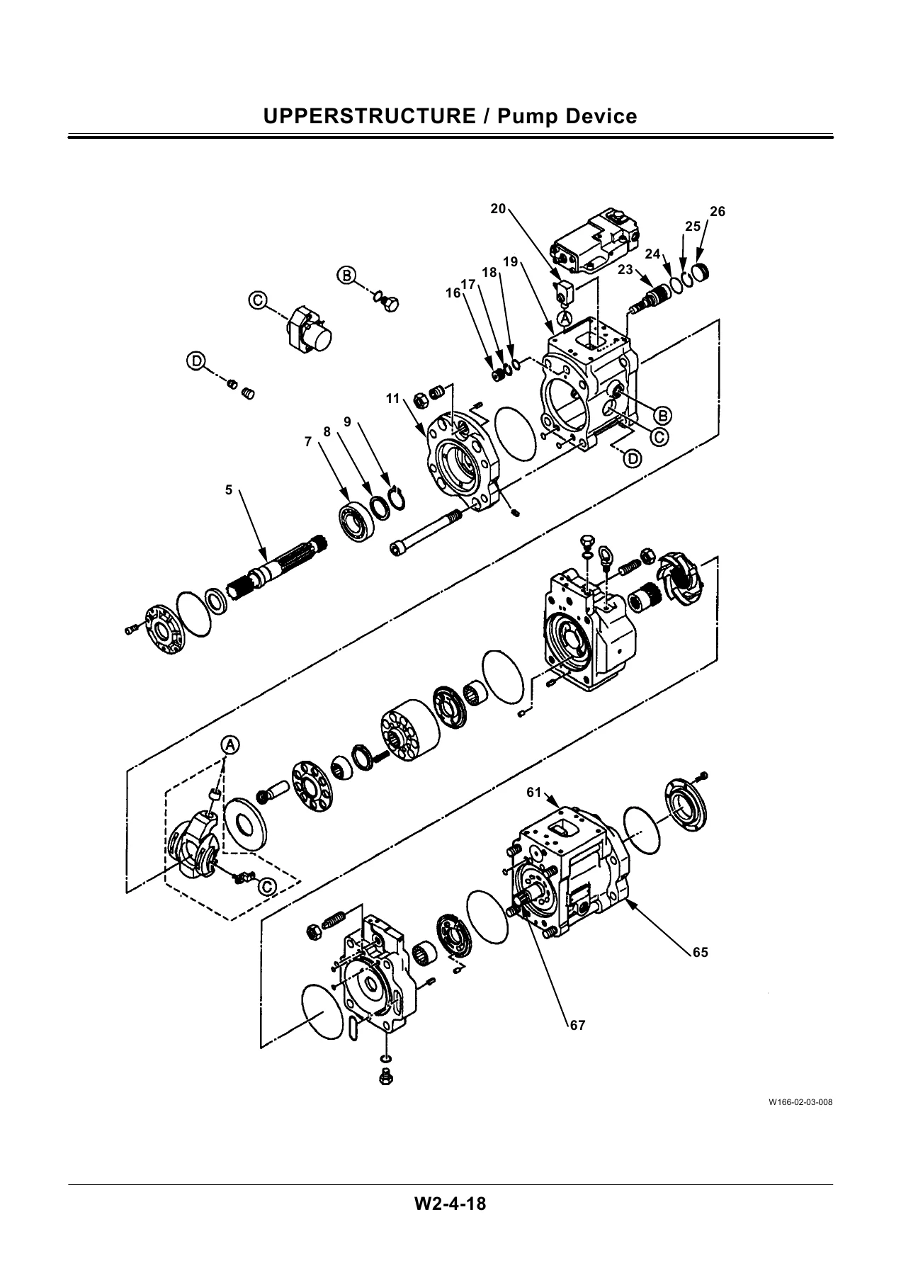
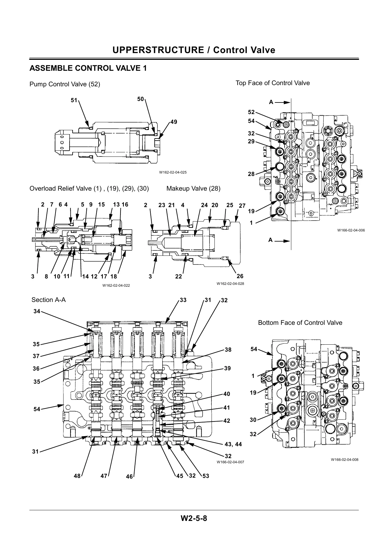
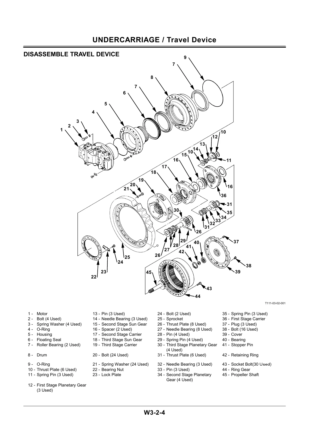
This structure gives the technician a clear path through every major assembly on the machine. The workshop manual does not merely list parts — it walks through removal and installation sequences, disassembly and assembly procedures, component-specific tightening torques, and maintenance standards with allowable limits that tell you when a part must be repaired or replaced. The control valve section alone spans multiple sub-assemblies, with detailed breakdowns of the 5-spool housing, overload relief valves, makeup valves, pump control valve, holding valve, load check valves, center bypass valve, shuttle valve, flow combiner valve, and arm regenerative valve. The pump device coverage includes full disassembly and assembly of the main pump, regulator, and pilot pump. The travel device section covers the travel motor, brake valve, and the complete travel reduction gear assembly with sprocket wear limits. The cylinder chapter addresses boom, arm, bucket, level, and dump cylinders with serial-number-specific procedures, ensuring the correct steps are used for the machine at hand.
What This Manual Helps You Do
- Remove and install the cab, counterweight, main frame, pump device, control valve, swing device, pilot valves, and front attachment
- Disassemble and reassemble the main pump, regulator, pilot pump, and pump transmission
- Overhaul the control valve, including all spool sections, relief valves, and auxiliary valves
- Service the swing motor, travel motor, and brake valve
- Repair the undercarriage: swing bearing, travel device, center joint, track adjuster, front idler, rollers, and tracks
- Rebuild boom, arm, bucket, level, and dump cylinders with correct torque values and seal installation
- Replace bushings and points, and check wear against maintenance standards
- Identify allowable limits for worn components and decide between repair and replacement
- Perform periodic replacement of critical hoses and parts on the recommended schedule
Each procedure includes the special tools required, wrench sizes, tightening torques in N·m, kgf·m, and lbf·ft, and step-by-step instructions. The manual also covers safety precautions, including how to relieve hydraulic pressure, handle high-pressure fluids safely, and support the machine properly during service work.
Detailed Coverage Highlights
The EX400-5 Workshop Manual goes deeper than a general repair guide. The pump device section breaks down the pump transmission into casing, bearings, gears, cartridges, sleeves, and retaining rings, with pressing and assembly instructions. The control valve section provides sectional diagrams and part lists for each sub-assembly, including the 5-spool and 4-spool housing configurations, overload relief valve settings, and the manifold that connects the spool banks. The swing device coverage includes the swing motor with its brake piston, friction plates, plungers, and relief valves, along with the maintenance standard for plunger clearance, shoe thickness, and friction plate wear. The travel device chapter covers the travel motor, brake valve, and three-stage planetary reduction gear, with detailed disassembly and assembly sequences and a maintenance standard for sprocket wear.
The undercarriage section addresses the swing bearing with its ball and support replacement procedure, the center joint with its seal and spindle assembly, the track adjuster with its high-pressure spring handling procedure, the front idler and rollers with their floating seal and bushing replacement, and the track with master pin removal and installation. The front attachment chapter covers the removal and installation of the complete front assembly, along with the boom, arm, bucket, level, and dump cylinders, including serial-number-specific disassembly and assembly procedures. The bushing and point section provides maintenance standards for pins, bushings, side cutters, and points.
Who This Manual Is For
This workshop manual is written for experienced technicians who need correct product information and service procedures. It assumes familiarity with heavy equipment repair and provides the manufacturer’s procedures, specifications, and standards rather than basic operating instructions. The manual also references the Operator’s Manual, Parts Catalog, and engine-specific publications for information outside its scope, making it part of a broader service library for the EX400-5 family.
Get Instant Access
IMAGES PREVIEW
The Hitachi EX400-5 Excavator Workshop Manual is delivered as a PDF download, available immediately after purchase. There is no shipping wait, no physical book to handle, and no risk of a greasy page in the shop. The file can be viewed on any device — laptop, tablet, or smartphone — and printed pages can be taken directly to the machine. Whether you are servicing the hydraulic pump, rebuilding a cylinder, replacing undercarriage components, or performing a complete machine overhaul, this manual provides the procedures, torque values, and maintenance standards needed to do the job correctly and safely. Instant PDF delivery means you can start the repair today.
Reviews
There are no reviews yet.