

Hitachi EX5600-6 Hydraulic Excavator Assembly Procedure Manual KO-382-01
Original price was: $44.95.$27.95Current price is: $27.95.
Hitachi EX5600-6 Hydraulic Excavator Assembly Procedure Manual KO-382-01 covering field assembly of the undercarriage, superstructure, loader and backhoe front attachments, hydraulic and electrical connections, tightening procedures, lifting arrangements, final checks and machine performance testing.
Description
Hitachi EX5600-6 Hydraulic Excavator Assembly Procedure Manual KO-382-01
The Hitachi EX5600-6 Hydraulic Excavator Assembly Procedure Manual KO-382-01 is a detailed field-assembly reference for the EX5600-6. It follows the machine from preparation of the assembly site and unpacking of transported components through undercarriage construction, connection of the main frame and superstructure, installation of major tanks and engine units, front-end attachment assembly, final inspections and machine-performance checks. The manual is built around practical assembly work, with illustrated sequences, component weights, lifting arrangements, required tools, tightening values, hydraulic connection instructions and checks intended to help the assembly team work safely, efficiently and accurately.
Field Assembly Planning and Preparation
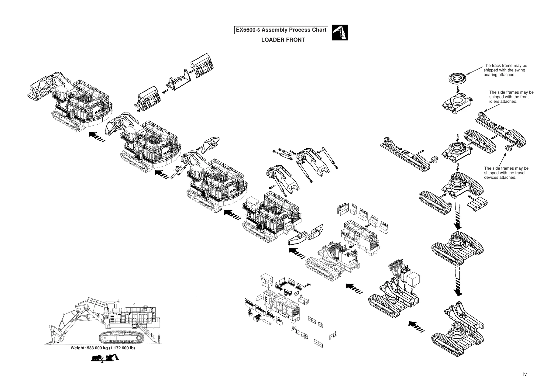
Before the major components are joined, the manual establishes the working conditions and equipment required for the job. Separate worker plans are provided for loader-front and backhoe-front configurations, together with transportation layouts showing how the machine is divided into major assemblies for delivery. Component drawings identify items such as the main frame, engine units, hydraulic oil tank, fuel tank, control valve unit, track frame, side frames, counterweights, boom, arm, cylinders and buckets, with weights and transportation dimensions where specified.
The preparation sections specify a firm, level work site and show the arrangement of major components before assembly begins. They also identify crane requirements, wire-rope sizes, shackles, sling equipment, chain blocks, lever blocks, wooden supports, hydraulic jacks, scaffolding, standard tools and special tools. The manual includes illustrated special-tool information for torque wrenches, power wrenches, a hydraulic power source, vacuum-pump equipment, guide pins, lifting tools and the front-attachment pin removal/insertion jig.
Safety, Lifting and Correct Joint Work
A substantial opening section is devoted to assembly safety and correct working practice. It covers lifting heavy components, communication between the leader and assembly crew, work at height, support of raised equipment, high-pressure hydraulic fluids, hot fluids, batteries, electrical isolation and safe use of power wrenches. The instructions repeatedly identify component weights, suitable wire ropes and lifting arrangements so that the crew can prepare for each lift before moving the part.
The manual also explains work practices that directly affect assembly quality. These include cleaning mating surfaces, protecting open hydraulic ports from contamination, connecting hoses without twisting them, handling O-rings, applying specified adhesive or sealant, tightening split-flange joints in the correct sequence and checking completed joints. Large-diameter mounting bolts receive particular attention, with specified torque values, wrench sizes, lubrication instructions and final marking procedures. Guidance for ORS joints, union joints and split-flange joints is illustrated step by step.
Undercarriage and Superstructure Assembly
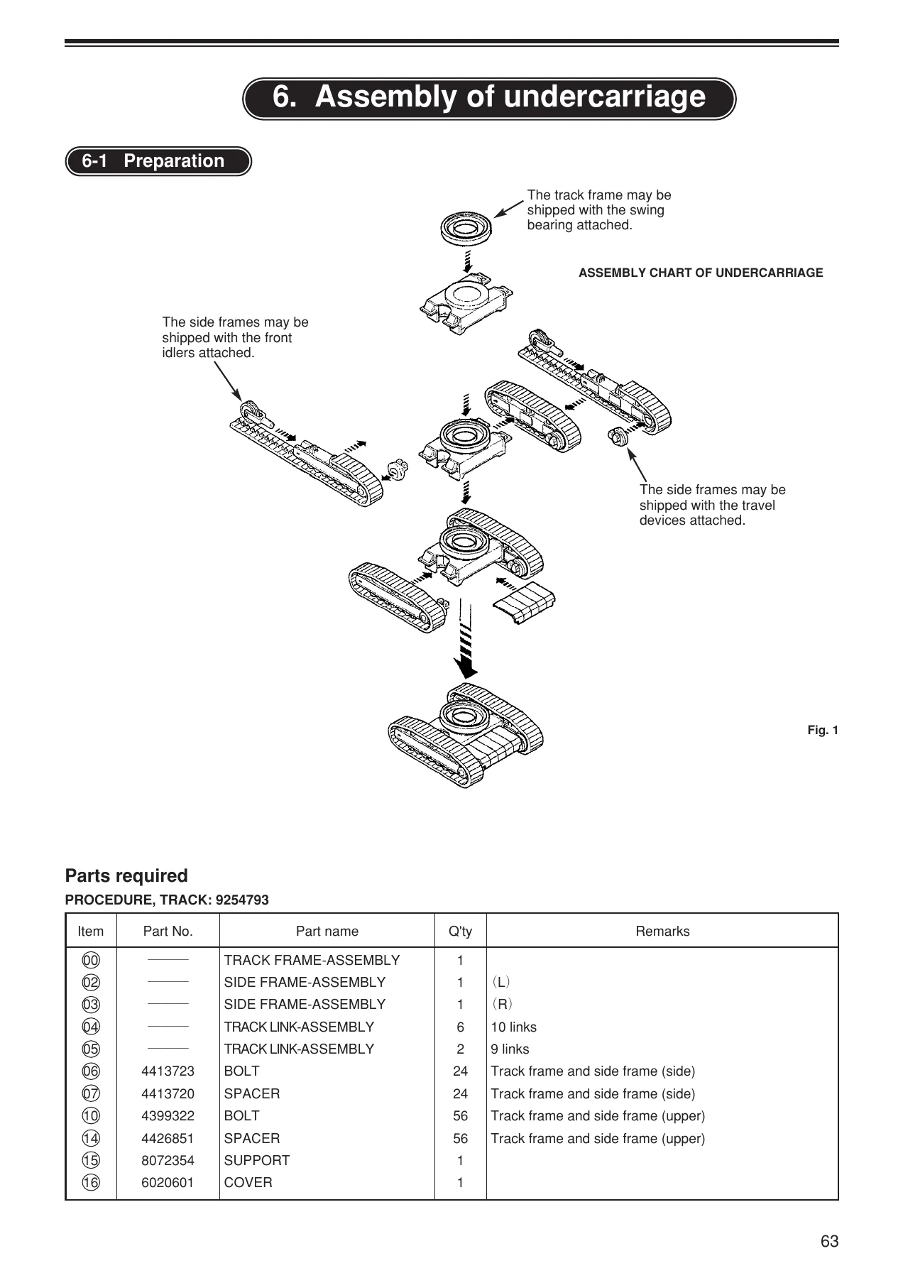
The EX5600-6 assembly procedure manual develops the undercarriage from transported track-link, side-frame and track-frame assemblies. Procedures cover preparation of track links, lifting and positioning the side frames, installation of front idlers and travel devices where required, connection of track links, preparation of the swing bearing, connection of the track frame to the side frames and final tightening of the major mounting bolts. Travel-motor piping, adjuster piping, grease piping, motor covers, steps and optional guard assemblies are addressed in their respective sequences.
Superstructure work begins with preparation of the undercarriage and main frame. The manual illustrates how the main frame is lifted with cranes, kept level, aligned over the swing bearing and carefully lowered while the swing-drive pinions are meshed with the internal gear. Guide pins, knock pins, clearances and the positioning of the swing-bearing soft zone are shown as part of this operation. Once the structures are joined, the connecting bolts are installed and tightened to the stated values, grease piping is connected and temporary swing-lock-valve arrangements used during alignment are restored.
From there, the procedures cover the center-joint hoses, control valve unit, hydraulic oil tank and fuel tank. Each major lift includes preparation information and connection details. Separate sequences then address the left and right engine units, their installation on the main frame, cooler-related equipment, hydraulic oil pump components, steps, filters, counterweights, monitor equipment and optional discharge lamps and back monitors. Later sections bring together the numerous hydraulic hoses, pipes, electrical connections and associated components required to complete the superstructure.
Loader and Backhoe Front-End Attachment Procedures
Both principal front configurations receive their own assembly coverage. The loader-front section includes preparation, boom mounting, bucket-cylinder installation, arm mounting, bucket mounting, track-link tension adjustment and the final trial-operation check. The backhoe-front section separately covers preparation and mounting of its boom, arm and bucket, followed by track tension adjustment and final trial operation. The manual also includes disassembly procedures for shipment after the respective assembly operations.
The loader and backhoe procedures are supported by diagrams showing lifting points, wire-rope arrangements, blocks and supports, component orientation, pin installation and hydraulic connections. This is particularly useful when handling large front-end structures because the assembly sequence depends not only on where each component fits, but also on how it is safely suspended and aligned during installation.
Final Checks and Performance Verification
Assembly does not end when the final component is installed. The manual provides checks after completing assembly, including inspection of the electrical system, boom, bucket, arm, frame and tracks, hardware, hydraulic system, lubrication points and protective devices. It directs the technician to check fluid and oil levels and to verify that parts have been correctly reassembled before operation.
The final performance section gives new-machine test conditions and procedures for checking operating performance. It includes travel-speed testing, track line-off measurement, track-link speed and front-attachment cylinder-speed checks for loader and backhoe configurations, together with cylinder-creep measurements. The document also contains completed-assembly check material for systematic inspection of field-assembled sections.
File Details
- Manual type: Assembly Procedure Manual
- Brand / model: Hitachi EX5600-6
- Equipment: Hydraulic Excavator
- Document number: KO-382-01
- Language: English
- Page count: 496 pages
- File format: PDF
Chapters Covered
- 1. Precautions
- 1-1. Safety precautions for servicemen
- 1-2. How to use a power wrench
- 1-3. Work precautions
- 2. Workers plan – Loader front
- 2-1. Transportation of Loader Front
- 2′. Workers plan – Backhoe front
- 2-1′. Transportation of Backhoe Front
- 3. Parts check
- 3-1. Check
- 4. Preparations – loader front
- 4′. Preparations – backhoe front
- 5. Machines, apparatus, tools, and materials necessary for assembly
- 6. Assembly of undercarriage
- 6-1. Preparation
- 6-2. Connection of track frame and side frames
- 6-3. Connection of travel motor piping and adjuster piping
- 6-4. Assembly of mission guards – Option
- 6-5. Assembly of motor guards – Option
- 6-6. Assembly of motor covers and steps
- 6-7. Disassembly procedures for shipment – Procedure, Track
- 7. Connection of undercarriage and superstructure
- 7-1. Preparations before connection
- 7-2. Preparation of undercarriage
- 7-3. Preparation of main frame
- 7-4. Connection of undercarriage and main frame assembly
- 7-5. Connection of piping to center joint
- 7-6. Assembly of control valve unit
- 7-7. Assembly of oil tank
- 7-8. Assembly of fuel tank
- 7-9. Assembly of engine unit – left
- 7-10. Assembly of engine unit – right
- 7-11. Installation of engine unit – right
- 7-12. Installation of engine unit – left
- 7-13. Installation of cooler unit, M/up piping, step, hyd.oil pump and etc.
- 7-14. Mounting of counterweights & filter assembly, monitor display and etc.
- 7-15. Assembly of discharge lamps and back monitors – Option
- 7-16. Connecting of various sections
- 7-17. Checking of stop valves
- 7-18. Final check of superstructure
- 7-19. Releasing air from main pumps
- 7-20. Trial operation of superstructure
- 7-21. Disassembly procedures for shipment
- 8. Mounting procedure for loader front-end attachment
- 8-1. Preparation
- 8-2. Mounting of boom
- 8-3. Installation of bucket cylinders
- 8-4. Mounting of arm
- 8-5. Mounting of bucket
- 8-6. Adjustment of track link tension
- 8-7. Final trial operation check
- 8-8. Disassembly procedures for shipment
- 8′. Mounting procedure for backhoe front-end attachment
- 8′-1. Preparation
- 8′-2. Mounting of boom
- 8′-3. Mounting of arm
- 8′-4. Mounting of bucket
- 8′-5. Adjustment of track link tension
- 8′-6. Final trial operation check
- 8′-7. Disassembly procedures for shipment
- 9. Checks after completing the assembly
- 10. Checking machine performance
Taken together, these chapters make the Hitachi EX5600-6 Hydraulic Excavator Assembly Procedure Manual KO-382-01 a working reference for the complete field-assembly sequence rather than a simple component overview. The procedures combine the order of work with the lifting, fastening, hydraulic, electrical and inspection information required at the corresponding assembly stage.
Complete EX5600-6 Assembly Work with the Correct Procedures
This manual supports the jobs involved in building the transported Hitachi EX5600-6 into an assembled machine, from track and frame work through major superstructure components, piping, engine-unit installation, front attachments and final performance verification. Using the specified lifting methods, connection practices, tightening torques, checks and assembly sequences matters when large components must be aligned correctly and hydraulic, mechanical and electrical connections must be completed without introducing avoidable assembly problems. The Hitachi EX5600-6 Hydraulic Excavator Assembly Procedure Manual KO-382-01 is delivered as an instant PDF after purchase, so there is no shipping delay or physical book to wait for. Open it on any device that can display PDF files and print the pages you need for workshop or field use.
IMAGES PREVIEW



Reviews
There are no reviews yet.