
★ TRUSTED BY 321,897+ PROFESSIONALS WORLDWIDE
🏢
Trusted Business
Verified & Licensed
🛡️
Virus Free Files
100% Safe Downloads
🔒
Secure Payment
SSL Protected
Instant Delivery
Available Immediately
Sale!

Hitachi Zaxis 200-3 240-3 270-3 Class Excavator Workshop Manual PDF

Original price was: $44.95.Current price is: $26.95.

The Hitachi Zaxis 200-3, 240-3 and 270-3 class Workshop Manual (W1V1-E-00), 570 pages covering disassembly, assembly, torque specs and maintenance standards for the full upperstructure, undercarriage and front attachment.

Instant PDF Download
Available immediately
💾
Save to Your Device
Download & keep forever
🛡️
Antivirus Scanned
100% virus-free
🌍
Trusted Worldwide
175,000+ customers

Description

Hitachi Zaxis 200-3 240-3 270-3 Class Excavator Workshop Manual PDF

This is the complete Hitachi-published Zaxis 200-3, 240-3 and 270-3 class Workshop Manual, Part No. W1V1-E-00, covering the full hydraulic excavator lineup built on these three chassis classes. If you’re servicing a Zaxis 200-3 class, 240-3 class, or 270-3 class machine and need factory-level disassembly, assembly, and torque data in one place, this Zaxis Workshop Manual is built exactly for that job.

File Details

  • Manual type: Workshop Manual (maintenance and repair volume)
  • Brand: Hitachi Construction Machinery
  • Machine classes covered: Zaxis 200-3, Zaxis 240-3, Zaxis 270-3
  • Document part number: W1V1-E-00
  • Language: English
  • Page count: 570 pages
  • File format: PDF, delivered as a digital download

Models Covered by This Zaxis Workshop Manual

  • Zaxis 200-3 class: ZX200-3, 210H-3, 210K-3, 210LCN-3, 240N-3
  • Zaxis 240-3 class: ZX240-3, 240LC-3, 250H-3, 250LC-3, 250LCN-3, 250LCH-3, 250K-3, 250LCK-3
  • Zaxis 270-3 class: ZX270-3, 270LC-3, 280LC-3, 280LCN-3

Complete PDF Bookmark Tree

Complete Bookmarks

The complete bookmarks in the “Hitachi Zaxis 200-3 240-3 270-3 Class Excavator Workshop Manual PDF” are as follows:

COVERp. 1
INTRODUCTIONp. 3
SAFETYp. 5
SECTION AND GROUP CONTENTSp. 41
SECTION 1 GENERALp. 43
Group 1 Precautions for Disassembling and Assemblingp. 45
Precautions for Disassembling and Assemblingp. 45
Group 2 Tightening Torquep. 53
Tightening Torque Specificationp. 53
Torque Chartp. 58
Piping Jointp. 61
Periodic Replacement of Partsp. 65
Group 3 Paintingp. 67
Paintingp. 67
Group 4 Bleeding Air from Hydraulic Oil Tankp. 71
Bleeding Air from Hydraulic Oil Tankp. 71
SECTION 2 UPPERSTRUCTUREp. 75
Group 1 Cabp. 77
Remove and Install Cabp. 77
Dimensions of Cab Glassp. 85
Group 2 Counterweightp. 99
List of Weightp. 99
Remove and Install Counterweightp. 100
Group 3 Main Framep. 103
List of Weightp. 103
Remove and Install Main Framep. 104
Group 4 Pump Devicep. 113
Remove and Install Pump Devicep. 113
Disassemble Pump Devicep. 120
Assemble Pump Devicep. 132
Disassemble Regulatorp. 150
Assemble Regulatorp. 152
Disassemble Solenoid Valvep. 154
Assemble Solenoid Valvep. 156
Structure of Pilot Pumpp. 158
Group 5 Control Valvep. 161
Remove and Install Control Valvep. 161
Disassemble Control Valve (4-Spool Side)p. 164
Assemble Control Valve (4-Spool Side)p. 176
Disassemble Control Valve (5-Spool Side)p. 194
Assemble Control Valve (5-Spool Side)p. 206
Disassemble Housingp. 218
Assemble Housingp. 220
Group 6 Swing Devicep. 223
Remove and Install Swing Devicep. 223
Disassemble Swing Devicep. 226
Assemble Swing Devicep. 234
Disassemble Swing Motor (ZX200-3 class, 240-3 class)p. 248
Disassemble Swing Motor (ZX270-3 class)p. 252
Assemble Swing Motor (ZX200-3 class, 240-3 class)p. 256
Assemble Swing Motor (ZX270-3 class)p. 260
Structure of Swing Parking Brake Switch Valvep. 264
Maintenance Standardp. 265
Group 7 Pilot Valvep. 267
Remove and Install Pilot Valvep. 267
Disassemble Right and Left Pilot Valvesp. 284
Assemble Right and Left Pilot Valvesp. 288
Disassemble Travel Pilot Valvep. 292
Assemble Travel Pilot Valvep. 296
Disassemble Positioning Pilot Valve (2-Piece Boom Only)p. 302
Assemble Positioning Pilot Valve (2-Piece Boom Only)p. 304
Group 8 Pilot Shut-Off Solenoid Valvep. 307
Remove and Install Pilot Shut-Off Solenoid Valvep. 307
Disassemble Pilot Shut-Off Solenoid Valvep. 308
Assemble Pilot Shut-Off Solenoid Valvep. 310
Group 9 Signal Control Valve Unitp. 313
Remove and Install Signal Control Valvep. 313
Structure of Signal Control Valvep. 316
Group 10 4-Spool Solenoid Valve Unitp. 319
Remove and Install 4- Spool Solenoid Valve Unitp. 319
Structure of 4-Spool Solenoid Valve Unitp. 320
Group 11 Enginep. 323
Remove and Install Enginep. 323
SECTION 3 UNDERCARRIAGEp. 349
Group 1 Swing Bearingp. 351
Remove and Install Swing Bearingp. 351
Disassemble Swing Bearingp. 354
Assemble Swing Bearingp. 356
Group 2 Travel Devicep. 359
Remove and Install Travel Devicep. 359
List of Weightp. 361
Disassemble Travel Devicep. 362
Assemble Travel Devicep. 374
Disassemble Travel Motorp. 390
Assemble Travel Motorp. 398
Disassemble Brake Valvep. 410
Assemble Brake Valvep. 414
Maintenance Standardp. 418
Group 3 Center Jointp. 421
Remove and Install Center Jointp. 421
Disassemble Center Jointp. 424
Assemble Center Jointp. 426
Group 4 Track Adjusterp. 429
Remove and Install Track Adjusterp. 429
Disassemble Track Adjusterp. 432
Assemble Track Adjusterp. 438
Group 5 Front Idlerp. 445
Remove and Install Front Idlerp. 445
Disassemble Front Idlerp. 448
Assemble Front Idlerp. 452
Maintenance Standardp. 456
Group 6 Upper and Lower Rollerp. 457
Remove and Install Upper Rollerp. 457
Remove and Install Lower Rollerp. 460
Disassemble Lower Rollerp. 464
Assemble Lower Rollerp. 466
Maintenance Standardp. 468
Group 7 Trackp. 471
Remove and Install Trackp. 471
Maintenance Standardp. 477
SECTION 4 FRONT ATTACHMENTp. 483
Group 1 Front Attachmentp. 485
List of Weightp. 485
Remove and Install Front Attachment (Mono Boom)p. 486
Remove and Install Front Attachment (2-Piece Boom)p. 494
Maintenance Standard (Mono Boom)p. 502
Maintenance Standard (2-Piece Boom)p. 508
Standard Dimensions for Arm and Bucket Connectionp. 516
Standard Dimensions for Arm and Boom Connectionp. 517
Group 2 Cylinderp. 519
Hydraulic Circuit Pressure Release Procedurep. 519
Remove and Install Cylinderp. 520
Disassemble Boom, Arm, Bucket Cylinders (ZX200-3 class, 240-3 class)p. 540
Disassemble Boom, Arm, Bucket Cylinders (ZX270-3lass)p. 546
Disassemble Positioning Cylinderp. 552
Assemble Boom, Arm, Bucket Cylinders (ZX200-3 class, 240-3 class)p. 554
Assemble Boom, Arm, Bucket Cylinders (ZX270-3lass)p. 560
Assemble Positioning Cylinderp. 564
Maintenance Standardp. 566

Chapters Covered

  • Section 1 General
    • Precautions for Disassembling and Assembling
    • Tightening Torque Specifications, Torque Chart, Piping Joint Torque
    • Periodic Replacement of Parts
    • Painting
    • Bleeding Air from the Hydraulic Oil Tank
  • Section 2 Upperstructure
    • Cab, Counterweight, Main Frame
    • Pump Device, Control Valve, Pilot Valve
    • Swing Device, Pilot Shut-Off Solenoid Valve
    • Signal Control Valve, 4-Spool Solenoid Valve Unit
    • Engine
  • Section 3 Undercarriage
    • Swing Bearing, Travel Device, Center Joint
    • Track Adjuster, Front Idler
    • Upper and Lower Roller, Track
  • Section 4 Front Attachment
    • Front Attachment: List of Weight, Remove/Install Mono Boom and 2-Piece Boom, Maintenance Standards, Standard Dimensions for Arm/Bucket/Boom Connections
    • Cylinder: Hydraulic Circuit Pressure Release Procedure, Remove/Install Cylinder, Disassemble/Assemble Boom, Arm and Bucket Cylinders, Disassemble Positioning Cylinder, Maintenance Standard

Across these four sections, this Zaxis 200-3 240-3 270-3 Workshop Manual walks a technician through every major structural and hydraulic component on the machine, from the cab and counterweight down to the track and idler assemblies, with the remove/install and disassemble/assemble sequences laid out group by group.

IMAGES PREVIEW

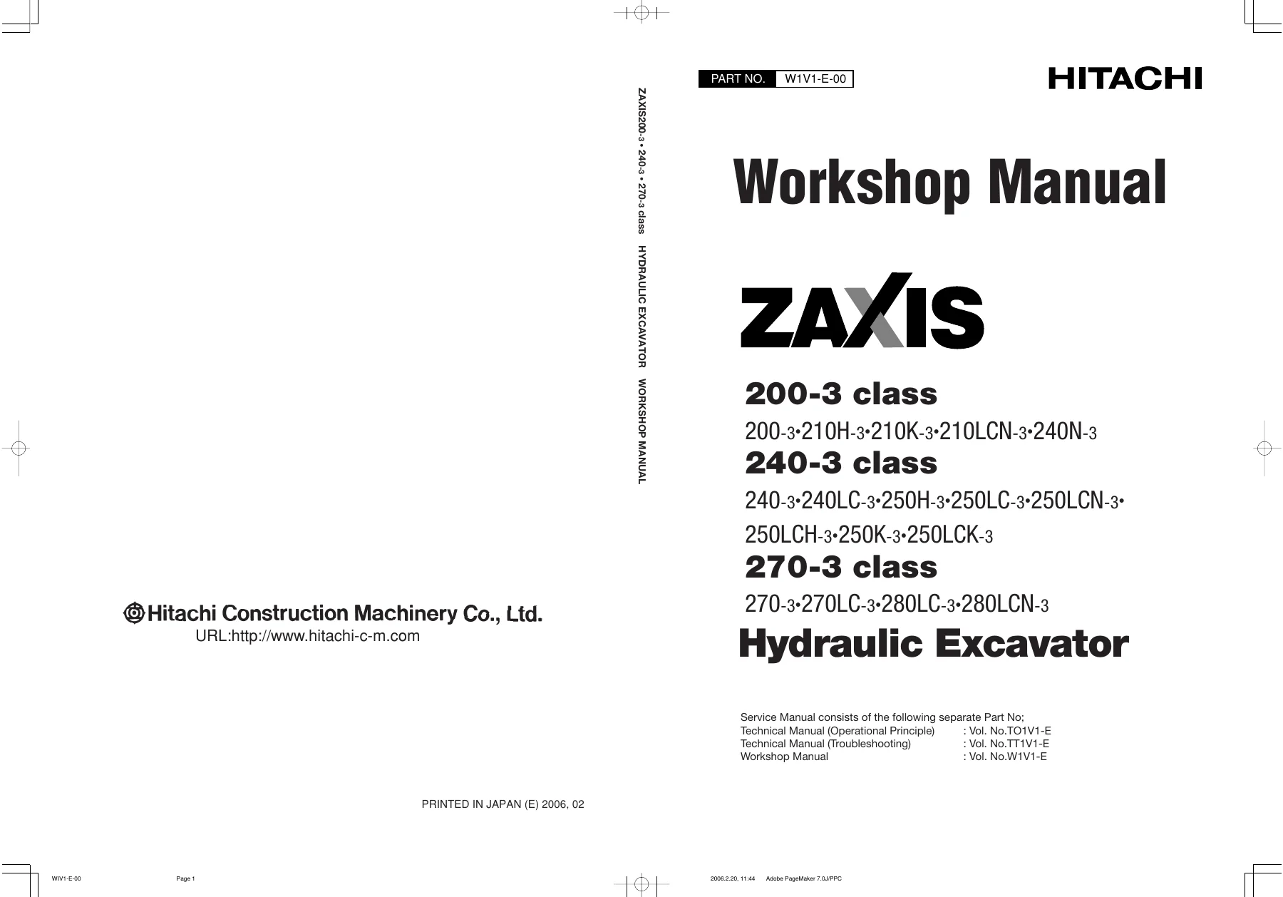
Hitachi Zaxis 200-3 240-3 270-3 Class Excavator Workshop Manual PDF — PDF page 1 preview
Hitachi Zaxis 200-3 240-3 270-3 Class Excavator Workshop Manual PDF — PDF page 48 preview
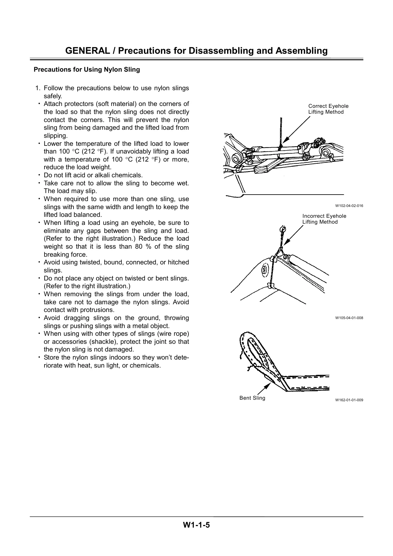
Hitachi Zaxis 200-3 240-3 270-3 Class Excavator Workshop Manual PDF — PDF page 49 preview

Tightening Torque and Maintenance Standards

A standout feature of this manual is its dedicated tightening torque section, with separate torque tables for the ZX200-3 class, ZX240-3 class, and ZX270-3 class. Values are given in N·m, kgf·m and lbf·ft for items such as engine cushion rubber mounting nuts, engine bracket bolts, hydraulic oil tank and fuel tank mounting bolts, radiator mounting bolts, pump and control valve mounting bolts, swing device and swing motor mounting bolts, cab mounting bolts, swing bearing mounting bolts, travel device mounting bolts, sprocket and roller mounting bolts, and track shoe and track guard bolts — with bolt diameter, quantity, and wrench size specified for each fastener. Component-level torque call-outs continue throughout the disassembly procedures in Sections 2 through 4, including swing motor, travel motor, and cylinder tie-rod torque values.

Why This Manual Matters

Working from the correct procedures and torque values in this Hitachi Zaxis Workshop Manual protects you from under- or over-torquing structural fasteners, misaligning floating seals, or damaging hydraulic components during reassembly — mistakes that are costly to fix on a machine this size. Whether you’re rebuilding a swing device, pulling the boom cylinders, or servicing the undercarriage on a Zaxis 200-3, 240-3 or 270-3 class excavator, this manual gives you Hitachi’s own documented sequence for the job.

This Hitachi Zaxis 200-3 240-3 270-3 Workshop Manual downloads instantly as a PDF after purchase — no shipping, no waiting. Read it on a laptop, tablet, or phone in the shop, or print out the sections you need at the bench.
Reviews

There are no reviews yet.

Be the first to review “Hitachi Zaxis 200-3 240-3 270-3 Class Excavator Workshop Manual PDF”

What Our Customers Say

★★★★★ Live reviews from customers
Loading customer reviews...
0
    0
    Your Cart
    Your cart is emptyReturn to Shop
    🛒
    Recently Purchased
    🕒 verified order