
Hitachi ZAXIS 650LC-3 670LCH-3 Hydraulic Excavator Technical Manual (Operational Principle) PDF
Original price was: $39.95.$23.95Current price is: $23.95.
Technical Manual (Operational Principle) for the Hitachi ZAXIS 650LC-3 and ZAXIS 670LCH-3 hydraulic excavators – 336 pages covering specifications, controller and CAN network, control system, ECM system, hydraulic and electrical systems, plus full component operation of pump, swing, control valve, pilot valve, travel device and signal control valve.
Description
Hitachi ZAXIS 650LC-3 and 670LCH-3 Technical Manual (Operational Principle)
This is the Operational Principle volume of the Hitachi service literature for the ZAXIS 650LC-3 and ZAXIS 670LCH-3 hydraulic excavators. Where a troubleshooting book tells you what to test and a workshop manual tells you how to disassemble, this book explains how the machine is designed to work in the first place – how the main controller, engine control module and information controller talk to each other over the CAN bus, how the pump regulators respond to control lever input, and how each valve in the hydraulic circuit is sequenced. It is the reference a technician reaches for when the symptom makes no sense yet and the circuit has to be understood before anything is taken apart.
File Details
- Manual type: Technical Manual (Operational Principle)
- Publication number: TO1J7-E (companion volumes in the same set: TT1J7-E Technical Manual / Troubleshooting and W1J7-E Workshop Manual)
- Brand / manufacturer: Hitachi Construction Machinery Co. Ltd.
- Models covered: ZAXIS 650LC-3 and ZAXIS 670LCH-3 hydraulic excavators
- Engine covered: ISUZU AH-6WG1XYSA-02
- Language: English
- File format: PDF
- Page count: 336 pages
Chapters Covered
- Section 1 – General
- Group 1 Specification
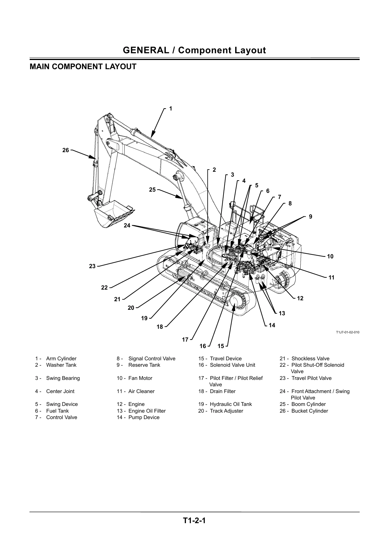
- Group 2 Component Layout
- Group 3 Component Specifications
- Section 2 – System
- Group 1 Controller (CAN network, MC Main Controller, ECM Engine Control Module, ICF Information Controller, Monitor Unit)
- Group 2 Control System (Engine Control, Pump Control, Valve Control, Other Controls)
- Group 3 ECM System (Fuel Injection Control, Fuel Injection Amount Correction, Preheating, EGR, Engine Stop)
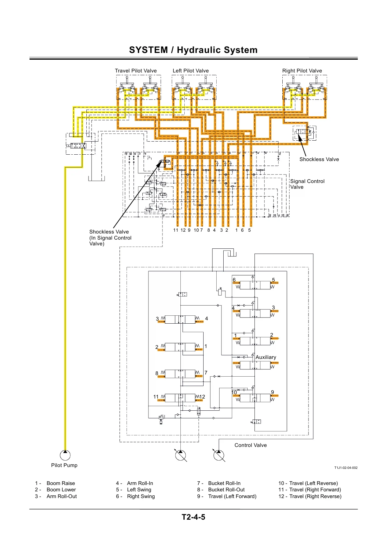
- Group 4 Hydraulic System (Pilot Circuit, Main Circuit, Counterweight Removal / Installation Circuit)
- Group 5 Electrical System (Main Circuit, Electric Power, Accessory, Starting, Charging, Surge Voltage Prevention, Pilot Shut-Off, Security Lock, Engine Stop, Security Horn, Working Light, Wiper / Washer)
- Section 3 – Component Operation
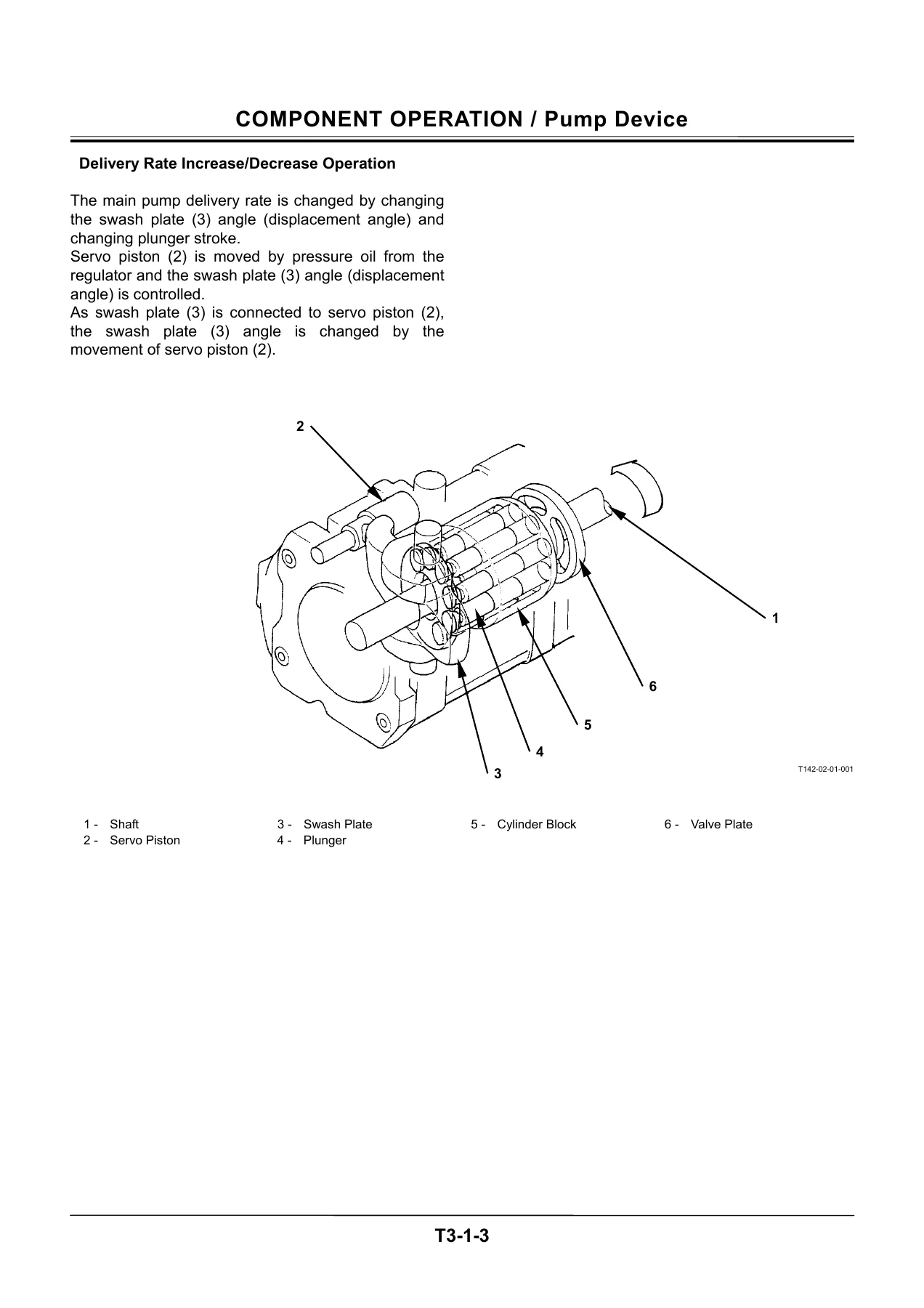
- Group 1 Pump Device (Main Pump and Fan Pump, Regulator for Main Pump, Regulator for Fan Pump, Pumps 1 / 2 Control Solenoid Valve, Fan Pump Control Solenoid Valve, Pilot Pump, pressure sensors)
- Group 2 Swing Device (Swing Reduction Gear, Swing Motor, Swing Parking Brake, Valve Unit)
- Group 3 Control Valve (Hydraulic Circuit, Main Relief Valve, Overload Relief Valve, Boom Overload Relief Control Valve, Flow Combiner Valve, Anti-Drift Valve, Regenerative Valve, Flow Rate Control Valve, Bypass Shut-Out Valve)
- Group 4 Pilot Valve (Operation, Shockless Function)
- Group 5 Travel Device (Travel Reduction Gear, Travel Motor, Travel Brake Valve, Parking Brake)
- Group 6 Signal Control Valve (Pilot Port, Shuttle Valve, Shockless Valve, Arm Flow Rate Control Valve Control Spool, Flow Combiner Valve Control Spool, Swing Parking Brake Release Spool)
- Group 7 Others – Uppertructure (Pilot Shut-Off Solenoid Valve, 4-Spool Solenoid Valve Unit, Pilot Relief Valve, Fan Motor, Fan Valve, Shockless Valve, Accumulator, Distribution Valve)
- Group 8 Others – Undercarriage (Swing Bearing, Center Joint, Track Adjuster)
Taken as a whole, the Operational Principle manual builds the ZAXIS 650LC-3 and 670LCH-3 up from the specification sheet at the front to the individual spool and piston at the back. The General section gives the working ranges, transport dimensions, ground pressure, swing and travel speeds and gradeability of both machines alongside a numbered component layout of the whole excavator. The System section then follows the signal path: engine control dial and pressure sensors into the MC, MC to ECM over CAN for engine speed, MC to the pump control solenoid valves for flow rate, and MC to the solenoid valve unit for relief pressure and valve selection. The Component Operation section ends the loop by opening each device in turn and describing what happens inside it, from the swash plate and servo piston of the main pump through the shuttle valves of the signal control valve to the negative-type parking brakes on the swing and travel motors.
Inside the Control, Hydraulic and Electrical Systems
The engine control chapter of this ZAXIS 650LC-3 / 670LCH-3 technical manual covers engine control dial control and ECO control, HP mode control, travel speed increase control, E mode control, auto-idle control and the optional attachment operation speed increase and decrease controls, each with its own trigger conditions and engine speed targets. The pump control chapter works through pump flow rate control, speed sensing control, horsepower control, relief flow rate reducing control, swing horsepower reducing control, overheat prevention control, attachment mode control, counterweight removal and installation control, fan pump flow rate control and pump learning control. Valve control covers pressure increase selection when traveling, power digging control, auto-power lift control, travel motor swash angle control, boom mode selector control and boom flow rate control valve control, followed by work mode control, rear monitoring display selection, level check, auto lubrication, travel alarm and overload alarm.
On the engine side, the ECM System group explains fuel injection amount, pressure, timing and rate control, fuel injection amount correction, preheating control, EGR control and the emergency engine stop control, with the suction control valve and two-way valve shown in circuit form. The Hydraulic System group splits the machine into the pilot circuit – operation control, pump control, valve control, swing parking brake release, travel motor swash angle control, hydraulic oil heat and emergency boom lower – and the main circuit, including the neutral circuit, single operation circuit and the combined operation circuits with the arm regenerative circuit and flow combiner valve. The Electrical System group traces the main circuit from the batteries and fusible link through the key switch positions to the starting circuit, charging circuit and alternator regulator operation, then through the surge voltage prevention circuit, pilot shut-off circuit, security lock circuit, engine stop circuit, security horn circuit, working light circuit and wiper / washer circuit.
Component-Level Detail for the Whole Machine
Section 3 is where the ZAXIS 650LC-3 and ZAXIS 670LCH-3 component operation chapters earn their keep. The pump device group covers the swash plate type variable displacement plunger main pumps and fan pump, then walks the main pump regulator through minimum flow rate, increasing flow rate and decreasing flow rate operation using flow rate control pressure, and the fan pump regulator through its link mechanism and control by both flow rate control pressure and own pump delivery pressure. The swing device group covers the two-stage planetary reduction gear, the swash plate axial plunger swing motor, the wet multi-disc negative swing parking brake and the make-up and relief valve unit with its shockless function. The control valve group takes the 4-spool and 5-spool sections apart across nine cross sections – main relief valve with set pressure increasing operation, overload relief valve with make-up function, boom overload relief control valve, flow combiner valve, boom and arm anti-drift valves, boom, arm and bucket regenerative valves, boom and arm flow rate control valves, and the bypass shut-out valves.
Further groups detail the front attachment / swing and travel pilot valves with their pressure proportional control output curves and the travel pilot valve damper, the travel motor with its counterbalance valve, overload relief valve, travel mode selection valve and parking brake, and the signal control valve with its shuttle valve matrix, boom raise shockless valve and the three control spools. The uppertructure group closes with the pilot shut-off solenoid valve, the 4-spool solenoid valve unit (SC, SF, SI and SG) and its proportional solenoid valve operation, the pilot relief valve with integral pilot filter, the fan motor and fan valve, the boom lower shockless valve, the accumulator and the optional auto lubrication distribution valve. The undercarriage group finishes on the single-row shear ball swing bearing, the 360 degree center joint and the track adjuster with its greased adjuster cylinder and spring.
Who This Operational Principle Manual Is For
This volume is written for the experienced technician – the same audience the manual itself names in its foreword – and it assumes you already know how to use a pressure gauge and a service tool. What it adds is the reasoning behind the readings. Knowing that the main relief valve is set at 31.9 MPa (325 kgf/cm2, 4638 psi) in normal operation and 34.3 MPa (350 kgf/cm2, 4987 psi) during pressure increasing operation only becomes useful once you understand that solenoid valve unit SG is applying back-pressure to the main relief valve during travel, power digging or auto-power lift. The same applies to the 30.9 MPa (315 kgf/cm2, 4490 psi) relief cut-off point, the swing horsepower reducing control that trims main pump 2 whenever the swing pressure sensor sees pilot pressure, and the boom mode selector that drops overload relief pressure on the boom lower circuit to reduce machine vibration during grading.
Because the manual covers both the ZAXIS 650LC-3 and the ZAXIS 670LCH-3, it also lets you compare the two machines directly – the operating weights, the bucket capacities, the cab heights and the working range figures for the 7.8 m boom, 6.8 m BE boom, 3.6 m arm, 4.2 m arm and 2.9 m BE arm combinations are all tabulated side by side.
Get the Hitachi ZAXIS 650LC-3 / 670LCH-3 Technical Manual Today
With this Operational Principle manual on hand you can follow a function from the control lever all the way to the actuator, understand why a controller commands a particular pump displacement, and read a hydraulic or electrical schematic with the confidence that you know what each component is supposed to be doing. That understanding is what shortens diagnosis, prevents unnecessary teardown, and keeps the machine working to the pressures, flow rates and control logic Hitachi designed into it.
IMAGES PREVIEW
The manual is delivered as an instant PDF download after payment – no shipping, no waiting. Open it on a laptop in the cab, on a tablet on the service truck, or print the pages you need for the job in front of you.

Reviews
There are no reviews yet.