
Hitachi ZAXIS450-3, ZX450LC-3, ZX500LC-3, ZX470H-3, ZX470LCH-3, ZX520LCH-3 Excavator Operational Principle Manual
Original price was: $39.95.$24.95Current price is: $24.95.
Operational principle manual for Hitachi ZAXIS 450-3, 470H-3 and 500-3 class excavators. Covers controllers, control systems, ECM, hydraulic and electrical systems with detailed component operation.
Description
File Details
- Manual Type: Operational Principle / Technical Training Manual
- Brand: Hitachi
- Models Covered: ZAXIS450-3, ZAXIS450LC-3, ZAXIS500LC-3, ZAXIS470H-3, ZAXIS470LCH-3, ZAXIS520LCH-3
- Document Number: TTLA0671-ZX450-3
- Language: English
- Page Count: 327
- File Format: PDF
Chapters Covered
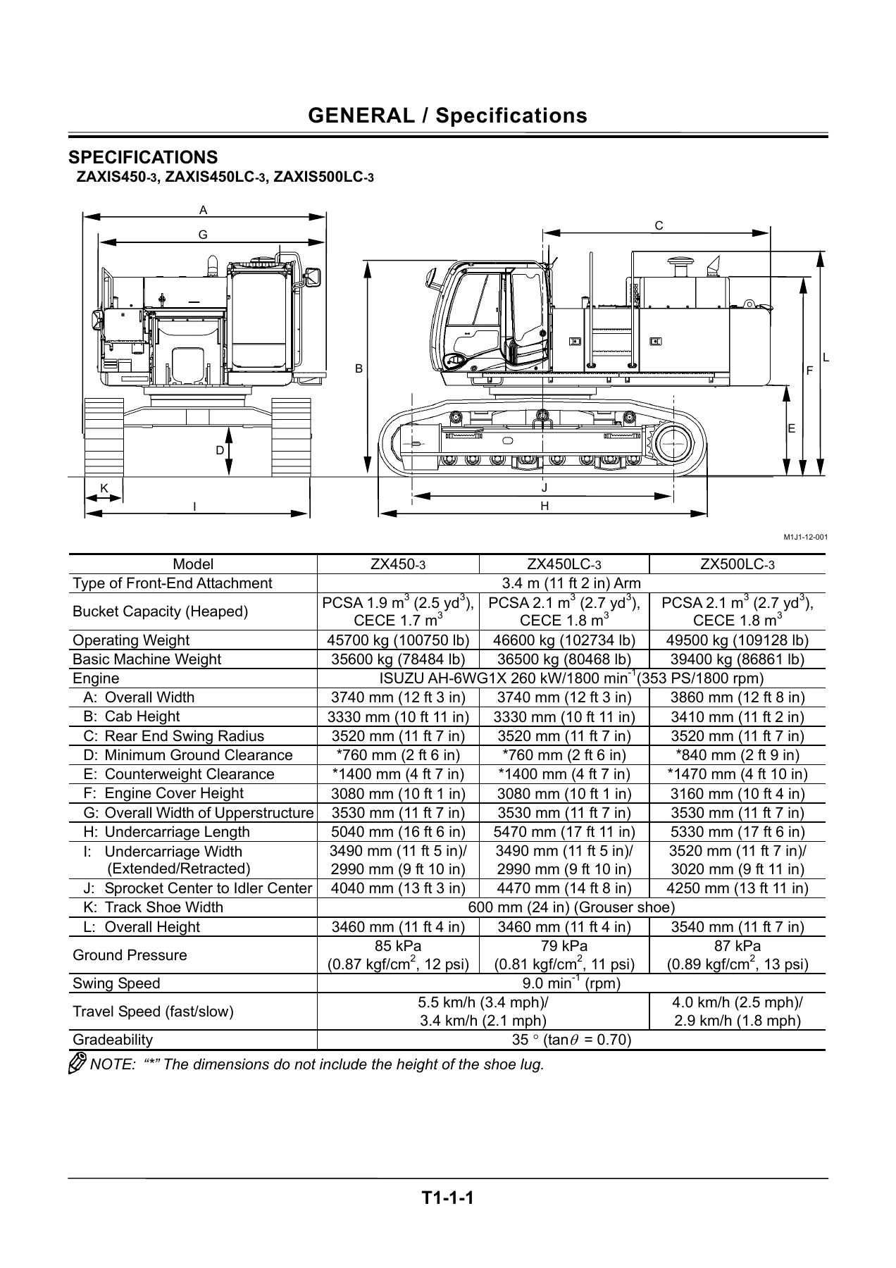
- Specifications — ZAXIS450-3, ZAXIS450LC-3, ZAXIS500LC-3
- Specifications — ZAXIS470H-3, ZAXIS470LCH-3, ZAXIS520LCH-3
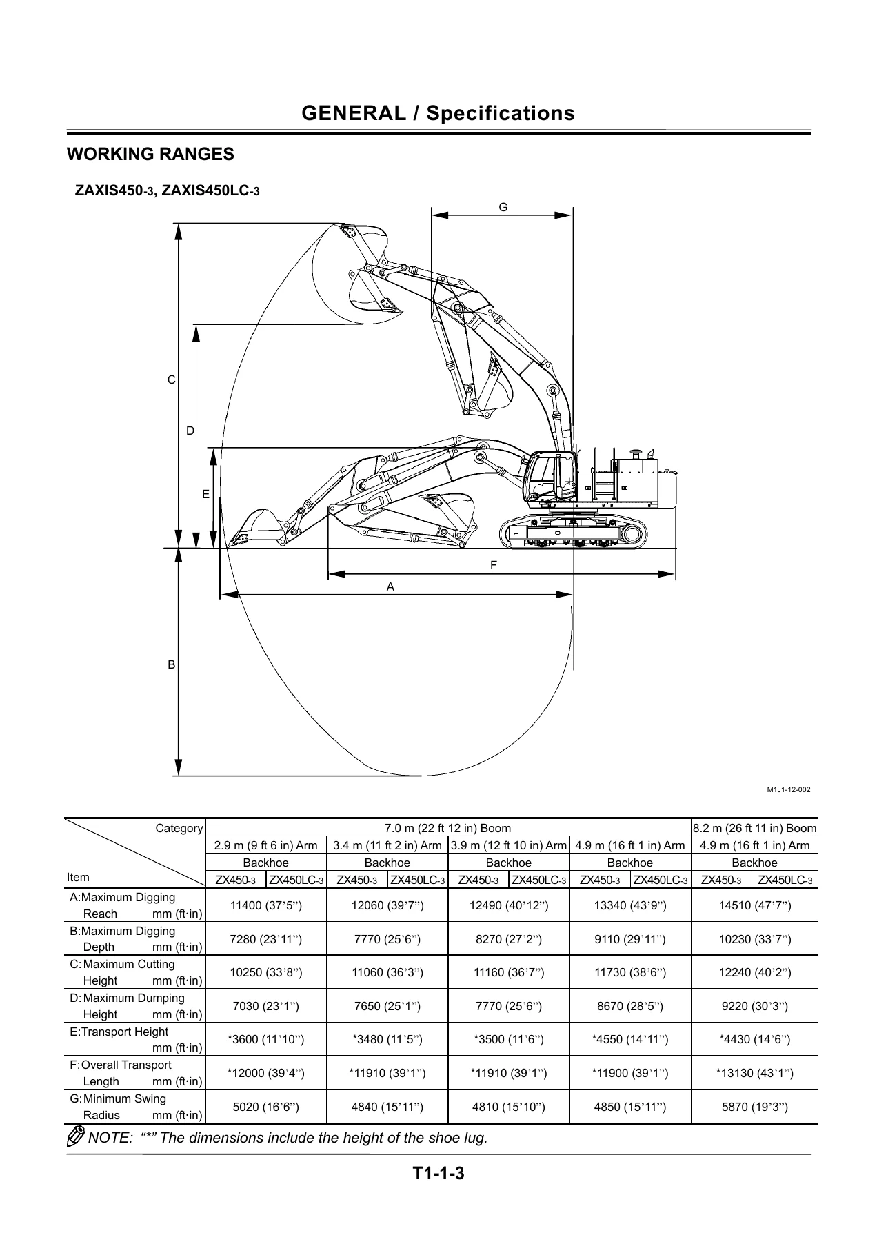
- Working Ranges — ZAXIS450-3, ZAXIS450LC-3
- Working Ranges — ZAXIS500LC-3
- Working Ranges — ZAXIS470H-3, ZAXIS470LCH-3, ZAXIS520LCH-3
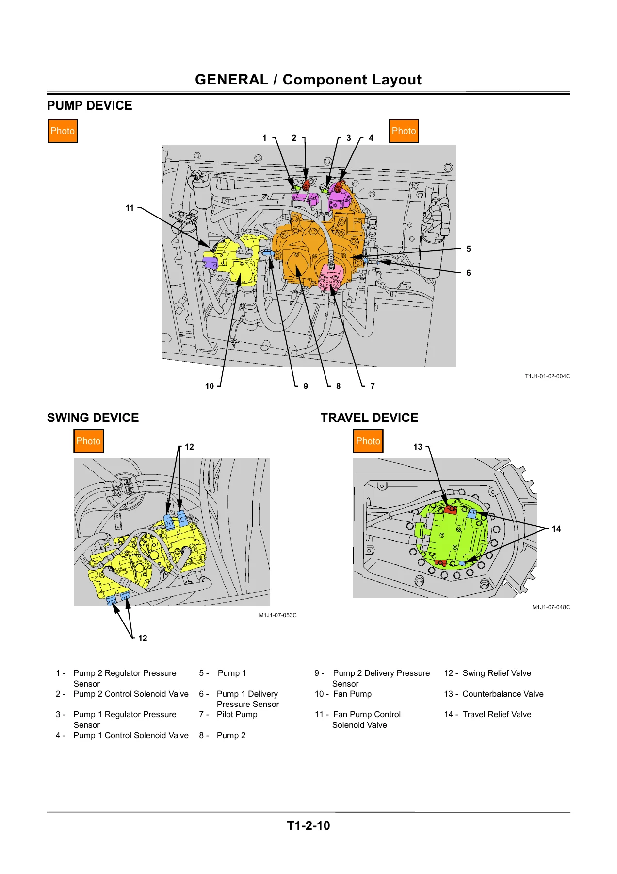
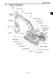
- Component Locations — Machine Overview and Layout
- Group 1 Controller — Outline, CAN, MC (Main Controller), ECM (Engine Control Module), ICF (Information Controller), Monitor Unit
- Group 2 Control System — Engine Control, Pump Control, Valve Control, Other Controls
- Group 3 ECM System — Fuel Injection Control, Fuel Injection Amount Correction, Preheating Control, EGR Control, Engine Stop Control
- Group 4 Hydraulic System — Pilot Circuit, Main Circuit, Counterweight Removal / Installation Circuit
- Group 5 Electrical System — Main Circuit, Electric Power Circuit, Accessory Circuit, Starting Circuit, Charging Circuit, Surge Voltage Prevention, Pilot Shut-Off Circuit, Security Lock Circuit, Engine Stop Circuit, Security Horn Circuit, Working Light Circuit, Wiper / Washer Circuit
- Group 1 Pump Device — Outline, Main Pump, Fan Pump, Regulator for Main Pump, Regulator for Fan Pump, Pump Control Solenoid Valve, Fan Pump Control Solenoid Valve, Pilot Pump, Pump Delivery Pressure Sensor, Pump Regulator Pressure Sensor
- Group 2 Swing Device — Outline, Swing Reduction Gear, Swing Motor, Swing Parking Brake, Valve Unit
- Group 3 Control Valve — Outline, Hydraulic Circuit, Main Relief Valve, Overload Relief Valve, Boom Overload Relief Control Valve, Flow Combiner Valve, Anti-Drift Valve, Regenerative Valve, Flow Rate Control Valve, Bypass Shut-Out Valve
- Group 4 Pilot Valve — Outline, Operation, Shockless Function
- Group 5 Travel Device — Outline, Travel Reduction Gear, Travel Motor, Travel Brake Valve, Parking Brake
- Group 6 Signal Control Valve — Outline, Pilot Port, Shuttle Valve, Shockless Valve, Arm Flow Rate Control Valve Control Spool, Flow Combiner Valve Control Spool, Swing Parking Brake Release Spool
- Others (Upperstructure) — Pilot Shut-Off Solenoid Valve, 4-Spool Solenoid Valve Unit, Proportional Solenoid Valve, Pilot Relief Valve, Fan Motor, Fan Valve, Shockless Valve, Accumulator, Distribution Valve
- Others (Undercarriage) — Swing Bearing, Center Joint, Track Adjuster
This operational principle manual for the Hitachi ZAXIS 450-3, 470H-3 and 500-3 class excavators gives technicians, field service personnel and advanced operators a complete system-level understanding of how these machines function. Rather than a step-by-step repair guide, it explains the logic behind the machine’s behaviour — how the Main Controller (MC), Engine Control Module (ECM) and Information Controller (ICF) communicate over the CAN bus, how pump flow is regulated by the Main Pump and Fan Pump regulators, how the control valve manages pressure and flow, and how the electrical system powers, protects and diagnoses itself. The document is structured around the actual machine systems, walking through the engine control dial, ECO control, HP mode, auto-idle, travel speed increase, E mode, and attachment operation speed controls. It then moves into pump control, including speed sensing, horsepower control, relief flow rate reducing, swing horsepower reducing, overheat prevention, and fan pump flow rate control. The valve control section details pressure increase selection, power digging, auto-power lift, travel motor swash angle, boom mode selector, and boom flow rate control. The ECM System group explains fuel injection control, injection amount correction, preheating, EGR and engine stop control. The hydraulic system group covers the pilot circuit, main circuit and counterweight removal circuit, while the electrical system group walks through every major circuit from electric power and starting to charging, pilot shut-off, security lock, engine stop, working light and wiper/washer. The Component Operation sections go deep into each major assembly: the pump device (main pump, fan pump, pilot pump and their regulators), swing device (swing motor, reduction gear, parking brake, valve unit), control valve (main relief, overload relief, boom overload relief control, flow combiner, anti-drift, regenerative, flow rate control and bypass shut-out valves), pilot valve operation including metering and full-stroke behaviour, travel device (travel motor, reduction gear, brake valve, parking brake and travel mode selection), signal control valve (shuttle valve, shockless valve and control spools), and the upperstructure and undercarriage components such as the pilot shut-off solenoid valve, proportional solenoid valves, fan motor and valve, accumulator, distribution valve, swing bearing, center joint and track adjuster. This level of operational detail is what separates a technician who can diagnose a problem correctly from one who simply replaces parts. Understanding the CAN communication network between MC, ECM, ICF and the monitor unit is essential for troubleshooting fault codes and machine behaviour. Knowing how the pump regulators respond to flow rate control pressure, engine speed changes and delivery pressure helps in diagnosing hydraulic performance issues. The control valve section explains exactly how the main relief valve, overload relief valves and flow combiner valve work together during single and combined operations, which is critical when diagnosing slow or weak functions. The electrical system group provides the circuit logic behind starting, charging, security lock, pilot shut-off and engine stop, so electrical faults can be traced methodically rather than by guesswork. The monitor unit and controller sections explain how data flows between the controllers and what information is available for troubleshooting, including fault code display, controller version, monitoring screen and operating conditions. Whether you are a field service technician, a workshop mechanic, a technical trainer or an advanced owner-operator, this operational principle manual delivers the system knowledge needed to understand, maintain and diagnose the ZAXIS450-3, ZX450LC-3, ZX500LC-3, ZX470H-3, ZX470LCH-3 and ZX520LCH-3 excavators with confidence. It covers the complete machine architecture — engine, hydraulic pumps, control valve, swing and travel systems, pilot circuits, electrical circuits, controllers and monitors — explaining not just what each component does but how it interacts with the rest of the machine. After purchase, the manual is available instantly as a PDF download. There is no shipping, no waiting and no physical book to carry. You can store it on any device — laptop, tablet or smartphone — and print the pages you need for the workshop. The PDF format makes it easy to reference specific sections, review diagrams on screen, and keep the complete document available wherever you are working. This is the document to have when you need to understand the operational logic behind the machine, not just the repair steps.
IMAGES PREVIEW

Reviews
There are no reviews yet.