
Hitachi ZH210-A / ZH210LC-A Hybrid Excavator Technical Manual – Operational Principle (TODCF-EN-00)
Original price was: $39.95.$23.95Current price is: $23.95.
545-page Hitachi Technical Manual (Operational Principle) for the ZH210-A and ZH210LC-A hybrid excavators. Explains how the engine, three-pump hydraulic system, control valve, signal control valve, travel and swing devices, ECM system and the complete hybrid swing system actually operate, with the control logic, circuit diagrams and component specifications behind every function.
Description
Hitachi ZH210-A / ZH210LC-A Hybrid Excavator Technical Manual – Operational Principle
The ZH210-A and ZH210LC-A are hybrid excavators: a conventional three-pump hydraulic platform with an electric swing assist system built into the swing device and the pump drive. This Hitachi ZH210-A / ZH210LC-A Hybrid Excavator Technical Manual – Operational Principle is the volume that explains how each of those systems is designed to behave, function by function, rather than how to remove and refit the parts. Published by Hitachi Construction Machinery Co., Ltd. under publication number TODCF-EN-00, the document runs 545 pages and is written for the experienced technician who needs to understand a circuit before diagnosing it.
File Details
- Manual type: Technical Manual – Operational Principle
- Brand: Hitachi Construction Machinery Co., Ltd.
- Models covered: ZH210-A, ZH210LC-A (ZH 210-A, 210LC-A)
- Publication number: TODCF-EN-00
- Language: English
- Page count: 545 pages
- File format: PDF
Chapters Covered
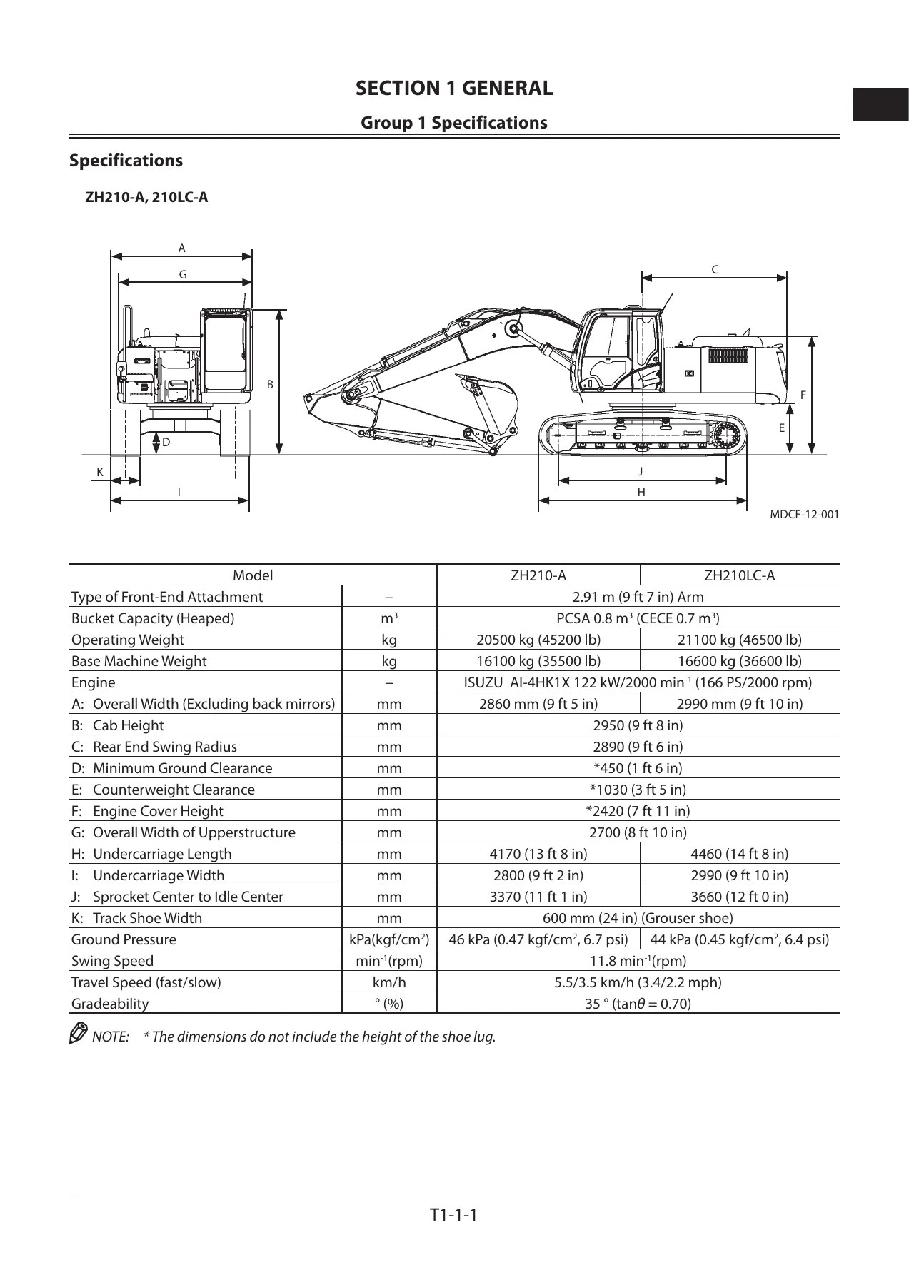
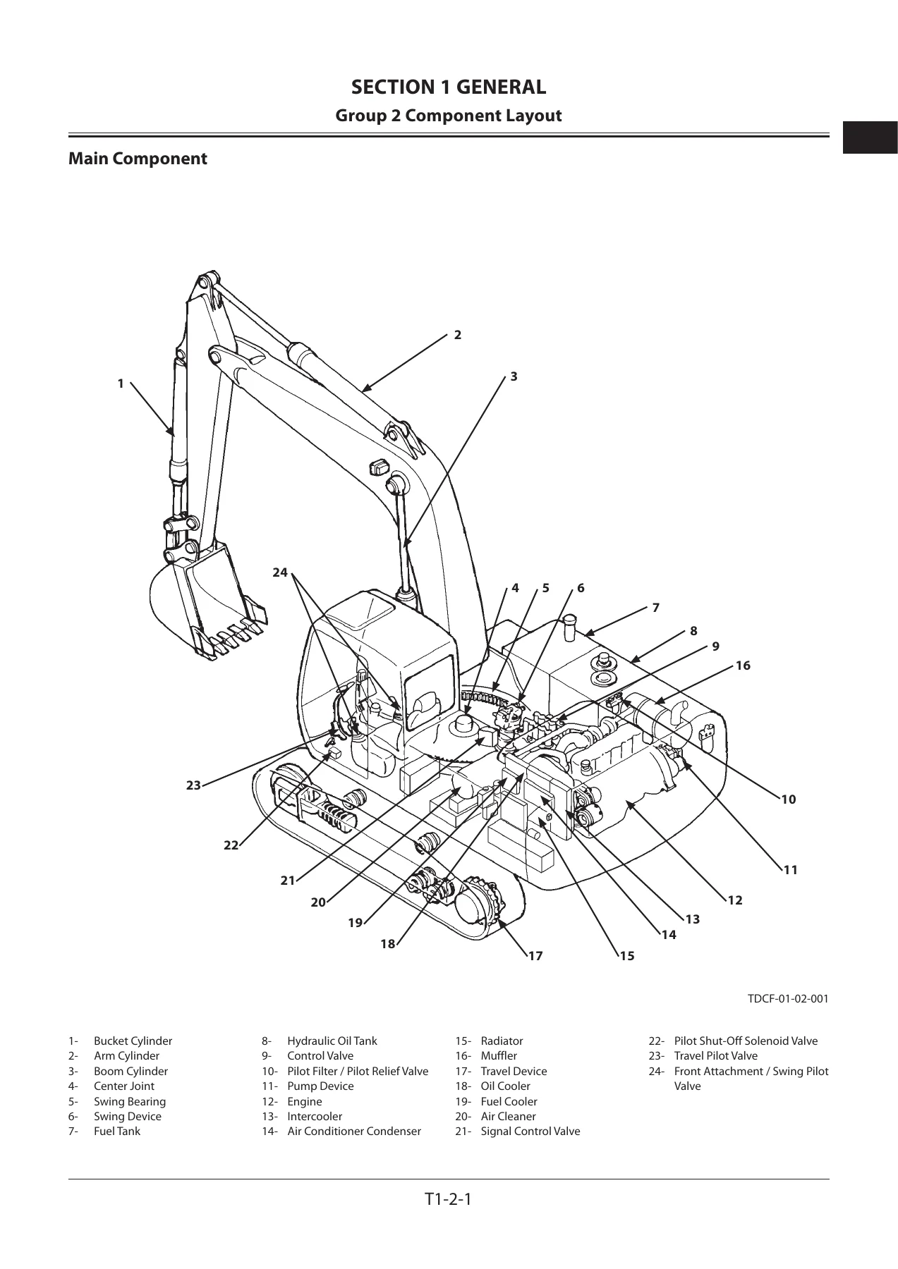
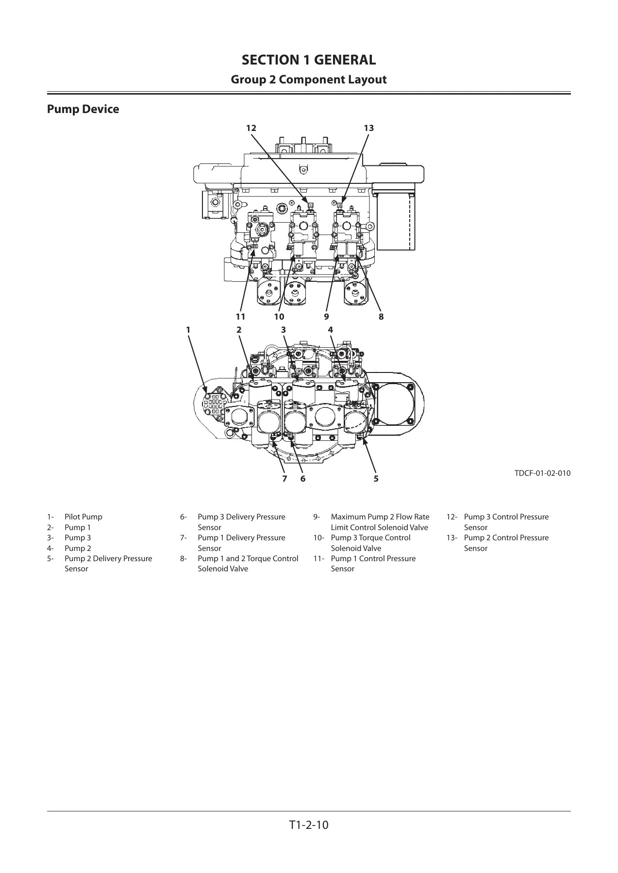
- Section 1 General – Group 1 Specifications (specifications, working ranges with grouser shoe); Group 2 Component Layout (main component, electrical system overview, rear tray, switch panel, around air cleaner, relay and sensor, battery, engine, pump device, around pump device, control valve, signal control valve, swing device, travel device, 5-spool solenoid valve unit, attachment spec parts hydraulic and electrical layout); Group 3 Component Specifications (engine, engine accessories, hydraulic component, electrical component)
- Section 2 System – Group 1 Controller; Group 2 Control System (input and output signal charts, engine control dial control, ECO control, power mode switch control, ECO mode control, PWR mode control, travel HP mode control, auto-idle control, hydraulic oil temperature auto-warming up control, radiator coolant temperature auto-warming up control, idle speed-up controls, engine speed slow down control, heater control, attachment operation speed increase and speed limit control, pump control, speed sensing control, swing relief cut control, pump torque decrease control, travel torque-up control, pump 1, 2 and 3 flow rate limit control, valve control standard system layout, auto-power lift control, travel motor displacement angle control, arm regenerative cut control, digging regenerative control, arm 1 and arm 2 flow rate control, attachment flow rate control, auxiliary flow combiner control, breaker 1 control, work mode control, auto shut-down control, breaker, swing, travel and overload alarm control); Group 3 ECM System (fuel injection amount control, fuel injection pressure control, fuel injection timing and rate control, fuel injection amount correction control, EGR control, glow control, engine oil pressure and fuel filter differential pressure alarm, engine stop circuit); Group 4 Hydraulic System (pilot circuit, pump control circuit, travel motor displacement angle control circuit, swing parking brake release circuit, main circuit, flow combiner circuit, relief circuit, travel and boom raise combined operation, digging regenerative circuit, arm regenerative cut circuit, arm 1 and arm 2 flow rate control circuit, bucket regenerative cut circuit, boom lower meter-in cut circuit, breaker, pulverizer and crusher circuit); Group 5 Electrical System (main circuit, CAN circuit, accessory circuit, starting circuit, charging circuit, surge voltage prevention circuit, pilot shut-off circuit, auto shut-down circuit, engine stop circuit, monitor circuit, security circuit, radio circuit, air conditioner circuit, work light circuit, wiper and washer circuit, cab light circuit)
- Section 3 Component Operation – Group 1 Pump Device (main pump, regulator control functions, solenoid valve, pilot pump, pump delivery and control pressure sensors); Group 2 Swing Device; Group 3 Control Valve (hydraulic circuit, flow combiner valve, main relief valve, overload relief valve with make-up function, regenerative valve, anti-drift valve, flow rate control valve, digging regenerative valve, boom lower meter-in cut valve, auxiliary flow combiner valve and bypass shut-out valve); Group 4 Pilot Valve (front attachment, swing, travel, auxiliary and positioning pilot valves, shockless function); Group 5 Travel Device (travel reduction gear, travel motor, parking brake, travel brake valve, overload relief valve, travel mode control); Group 6 Signal Control Valve (pilot ports, shuttle valve, shockless valve, pump flow rate control valves, flow combiner valve control spool, swing parking brake release spool); Group 7 Others Upperstructure (pilot shut-off solenoid valve, solenoid valves, hose rupture valve, pilot relief valve, recirculation valve); Group 8 Others Undercarriage (swing bearing, center joint, track adjuster)
- Section 6 Hybrid System – Group 1 General (hybrid system outline, controllers, electric component, power electrical circuit, monitor icon states); Group 2 Component Layout (main component, electrical system overview and rear tray, assist alternator motor, swing device, swing control solenoid valve unit, swing pilot pressure control solenoid valve unit); Group 3 Component Specifications (parts related with hybrid, cooling system for hybrid system); Group 4 Control of Hybrid System (start-up control, hydraulic-electric complex swing control, hydraulic independent swing control, energy management control, stop control, fault processing control, swing parking brake, cooling system, electric power circuit and starting circuit); Group 5 Component Operation (assist alternator motor, swing device, swing reduction gear, swing hydraulic motor, swing parking brake, valve unit, swing low-pressure relief valve unit, swing electric motor, swing pilot pressure control solenoid valve unit, swing control solenoid valve unit, HCU, PCU, capacitor unit)
Read together, those sections answer the question that a parts list or a wiring pinout cannot: what is the machine supposed to be doing right now, and why. The control system chapter maps every input – engine control dial, power mode switch, auto-idle switch, travel mode switch, pilot shut-off switch, the pump delivery and control pressure sensors, the boom raise, arm roll-in, bucket roll-in, swing, travel and attachment pressure sensors, hydraulic oil temperature – to the output that MC, ECM or HCU produces in response. The pump chapter then shows how that command reaches the regulator and changes the cylinder block angle. The hydraulic system chapter follows the oil itself: which pump feeds which spool, where the parallel and tandem circuits sit, when the flow combiner valve shifts, when the digging regenerative valve is cut in, and how the bucket regeneration cut valve behaves under light and heavy load. The electrical system chapter covers the CAN 0 and CAN 1 networks, the starting, charging, surge voltage prevention, pilot shut-off, auto shut-down and engine stop circuits, and the monitor, security, work light, wiper and cab light circuits.
What Makes This Operational Principle Volume Different
This is not a removal-and-installation book, and it is not a fault-code list. It is the explanation layer that sits underneath both. Because the ZH210-A and ZH210LC-A use three main pumps with individual regulators, a signal control valve that decides which pump control pressure reaches which regulator, and a set of 5-spool and auxiliary solenoid valve units that cut in regeneration, flow rate control and relief pressure changes on command, the behaviour of the machine on a job site is the sum of several control decisions taken at the same moment. The operating principle chapters take those decisions one at a time and show the conditions that trigger them, so a technician can reason about an unexpected machine response instead of guessing.
Hybrid System Coverage
The hybrid half of the machine gets its own full section, and it is the reason this manual exists in a separate hybrid edition. It explains the relationship between HCU, PCU, the capacitor unit, the swing electric motor mounted between the swing hydraulic motor and the swing reduction gear, and the assist alternator motor installed on the pump transmission. It covers start-up control, the initial charge of the capacitor, hydraulic-electric complex swing control through acceleration, constant speed, deceleration and stop, hydraulic independent swing control as the fallback when the electric side is unavailable, energy management control for capacitor charge and discharge, stop control, fault processing control, and the swing parking brake logic. Component-level chapters then break open the swing hydraulic motor, swing parking brake, valve unit with its dampener, low-pressure relief valve unit, the HCU, PCU and capacitor unit with their input and output signals. The machine is designed so that when the hybrid system is abnormal it can still be operated on the standard hydraulic system alone, and the manual explains how that transition is made.
Specifications and Reference Values
The general section carries the numbers a technician needs before touching anything: engine performance data for the ISUZU 4HK1XYSA-07, main pump theoretical displacement, rated and relief set pressures, pilot pump displacement, control valve and swing relief settings, swing and travel reduction gear ratios, travel motor displacement, parking brake release pressures, boom, arm and bucket cylinder rod diameters, bore, stroke, retracted lengths and plating thickness, hose rupture valve relief setting, pilot valve plunger strokes, solenoid valve coil resistances, filter filtration ratings, battery, relay, sensor, horn, illumination and air conditioner specifications, plus the hybrid component specifications for the assist alternator motor, swing electric motor, PCU, capacitor unit, swing low-pressure relief valve unit and the swing solenoid valve units.
IMAGES PREVIEW
Instant PDF Delivery
With this Hitachi ZH210-A / ZH210LC-A Hybrid Excavator Technical Manual – Operational Principle on the bench, you can trace a control function from the switch or sensor that requests it, through MC, ECM or HCU, into the pump regulator, signal control valve or control valve spool that carries it out, and on to the cylinder, motor or capacitor that responds – which is exactly what is needed when a machine does something the operator did not ask for, or refuses to do something it should. The hybrid swing chapters in particular give you the reasoning behind the assist, regeneration and fallback behaviour that no conventional excavator manual contains. Delivery is instant: the PDF is available for download immediately after payment, with no shipping and no waiting. Read it on a laptop, tablet or phone in the workshop, or print the sections you need for the machine.

Reviews
There are no reviews yet.