Hitachi ZW 180 Wheel Loader Operational Principle Technical Manual (TO4GD-E-00) – PDF Download
Original price was: $59.95.$25.95Current price is: $25.95.
- Hitachi ZW 180 Wheel Loader Operational Principle Technical Manual
- Part No:TO4GD-E-00
Description
Hitachi ZW 180 Wheel Loader Operational Principle Technical Manual (TO4GD-E-00)
File Details:
Hitachi ZW 180 Wheel Loader Operational Principle Technical Manual (TO4GD-E-00)
- Manual Language:English
- Pages: 374
- Size: 15.2 MB
- Downloadable:Yes
- Format:PDF
HITACHI ZW 180 WHEEL LOADER OPERATIONAL PRINCIPLE TECHNICAL MANUAL (TO4GD-E-00) – PDF DOWNLOAD:
Image Preview:
Description:
Hitachi ZW 180 Wheel Loader Operational Principle Technical Manual (TO4GD-E-00)
TO THE READER
• This manual is written for an experienced technician to provide technical information needed to maintain and repair this machine.
• Be sure to thoroughly read this manual for correct product information and service procedures.
• If you have any questions or comments, at if you found any errors regarding the contents of this manual, please contact using “Service Manual Revision Request Form” at the end of this manual.
ADDITIONAL REFERENCES
• Please refer to the materials listed below in addition to this manual.
• The Operator’s Manual
• The Parts Catalog
• The Engine Manual
• Parts Catalog of the Engine
• Hitachi Training Material
MANUAL COMPOSITION
• This manual consists of three portions: the Technical Manual (Operational Principle), the Technical Manual (Troubleshooting) and the Workshop Manual.
• Information included in the Technical Manual (Operational Principle): technical information needed for redelivery and delivery, operation and activation of all devices and systems.
• Information included in the Technical Manual (Troubleshooting): technical information needed for operational performance tests, and troubleshooting procedures.
• Information included in the Workshop Manual: technical information needed for maintenance and repair of the machine, tools and devices needed for maintenance and repair, maintenance standards, and removal/installation and assemble/ disassemble procedures.
Table Of Contents:
Hitachi ZW 180 Wheel Loader Operational Principle Technical Manual (TO4GD-E-00)
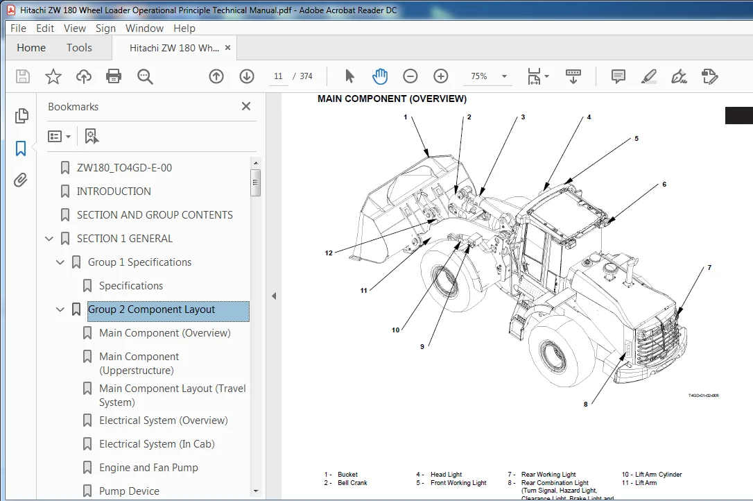
ZW180_TO4GD-E-00..............................................................................  1
INTRODUCTION..................................................................................  3
SECTION AND GROUP CONTENTS....................................................................  5
SECTION 1 GENERAL.............................................................................  7
	Group 1 Specifications....................................................................  9
		Specifications........................................................................  9
	Group 2 Component Layout.................................................................. 11
		Main Component (Overview)............................................................. 11
		Main Component (Upperstructure)....................................................... 12
		Main Component Layout (Travel System)................................................. 13
		Electrical System (Overview).......................................................... 14
		Electrical System (In Cab)............................................................ 15
		Engine and Fan Pump................................................................... 20
		Pump Device........................................................................... 21
		Drive Unit............................................................................ 21
		Control Valve......................................................................... 22
		Ride Control Valve(Optional).......................................................... 23
		Charging Block........................................................................ 23
		Fan Motor............................................................................. 23
		Steering Valve........................................................................ 24
		Emergency Steering Pump (Optional).................................................... 24
	Group 3 Component Specifications.......................................................... 25
		Engine................................................................................ 25
		Engine Accessories.................................................................... 29
		Hydraulic Component................................................................... 31
		Electrical Component.................................................................. 36
SECTION 2 SYSTEM.............................................................................. 41
	Group 1 Control System.................................................................... 43
		General............................................................................... 43
		Engine Control........................................................................ 48
		Pump Control.......................................................................... 57
		Transmission Control.................................................................. 62
		Other Controls........................................................................ 83
		Control by Electric and Hydraulic Combined Circuit.................................... 93
	Group 2 ECM System........................................................................107
		Outline...............................................................................107
		Fuel Injection Control................................................................108
		Engine Start Control..................................................................110
		Other Controls........................................................................111
	Group 3 Hydraulic System..................................................................117
		Outline...............................................................................117
		Main Circuit..........................................................................118
		Pilot Circuit.........................................................................129
		Steering Circuit......................................................................142
		Hydraulic Drive Fan Circuit...........................................................148
	Group 4 Electrical System.................................................................151
		Outline...............................................................................151
		Main Circuit..........................................................................152
		Electric Power Circuit................................................................153
		Indicator Light Check Circuit.........................................................154
		Accessory Circuit.....................................................................155
		Preheat Circuit.......................................................................156
		Starting Circuit......................................................................158
		Charging Circuit......................................................................162
		Serge Voltage Prevention Circuit......................................................166
		Engine Stop Circuit...................................................................168
		Lamplight Circuit.....................................................................169
		Head Light Circuit....................................................................170
		Turn Signal Circuit...................................................................174
		Brake Light Circuit...................................................................175
		Hazard Light Circuit..................................................................176
		Horn Circuit..........................................................................177
		Reverse Light/Buzzer Circuit..........................................................178
		Parking Brake Circuit.................................................................180
		Emergency Steering Check Circuit (Optional)...........................................182
SECTION 3 COMPONENT OPERATION.................................................................187
	Group 1 Pump Device.......................................................................189
		Outline...............................................................................189
		Main Pump.............................................................................190
		Regulator.............................................................................192
		Priority Valve........................................................................206
		Pilot Pump............................................................................207
		Pump Delivery Pressure Sensor.........................................................207
		Steering Main Relief Valve............................................................208
	Group 2 Control Valve.....................................................................209
		Outline...............................................................................209
		Hydraulic Circuit.....................................................................216
		Main Relief Valve.....................................................................220
		Overload Relief Valve.................................................................222
		Restriction Valve.....................................................................227
		Negative Control Valve................................................................228
		Flow Rate Control Valve...............................................................230
	Group 3 Hydraulic Fan Motor...............................................................233
		Outline...............................................................................233
		Operation.............................................................................236
		Flow Rate Control Valve...............................................................238
		Reverse Rotation Control Valve........................................................240
		Fun Pump..............................................................................242
	Group 4 Steering Pilot Valve..............................................................243
		Outline...............................................................................243
		Construction..........................................................................244
		Operation.............................................................................245
	Group 5 Steering Valve....................................................................249
		Outline...............................................................................249
		Operation.............................................................................252
		Steering Overload Relief Valve........................................................256
	Group 6 Pilot Valve.......................................................................259
		Outline (Standard Lever Type Pilot Valve for Front Attachment)........................259
		Operation.............................................................................260
		Electromagnetic Detent................................................................264
		Outline (Joystick Type Pilot Valve for Front Attachment)..............................265
		Operation.............................................................................266
		Electromagnetic Detent................................................................270
		Outline (Two-Derectional Lever Type Pilot Valve for Additional Circuit) (Optional)....271
		Operation.............................................................................272
		Outline (Joystick Type Pilot Valve for Additional Circuit) (Optional).................275
		Operation.............................................................................276
	Group 7 Charging Block....................................................................283
		Outline...............................................................................283
		Priority Valve........................................................................288
		Pilot Relief Valve....................................................................289
		Pump Torque Control Proportional Solenoid Valve.......................................290
		Service Brake Accumulator / Pilot Accumulator.........................................291
		Parking Brake Solenoid Valve..........................................................292
		Service Brake Pressure Sensor.........................................................294
		Parking Brake Pressure Sensor.........................................................294
	Group 8 Ride Control Valve................................................................295
		Outline...............................................................................295
		Operation.............................................................................298
		Charge-Cut Spool......................................................................300
		Overload Relief Valve.................................................................302
		Ride Control Accumlator...............................................................304
		Drain Plug............................................................................305
	Group 9 Drive Unit........................................................................307
		Outline...............................................................................307
		Torque Converter......................................................................308
		Transmission..........................................................................310
		Transmisson Regulator Valve...........................................................332
		Transmission Control Valve............................................................334
		Manual Spool (Emergency Travel Spool).................................................342
		Proportional Solenoid Valve...........................................................344
		Parking Brake.........................................................................346
	Group 10 Axle.............................................................................349
		Outline...............................................................................349
		Differential..........................................................................350
		Torque Proportioning Differential (TPD)...............................................354
		Limited Slip Differential (LSD) (Optional)............................................356
		Service Brake.........................................................................358
		Final Drive / Axle Shaft..............................................................360
	Group 11 Brake Valve......................................................................361
		Outline...............................................................................361
		Operation.............................................................................364
	Group 12 Others...........................................................................367
		Pilot Shut-Off Valve..................................................................367
		Propeller Shaft.......................................................................368
		Emergency Steering Check Block........................................................369
		Emergency Steering Pump (Optional)....................................................370
SERVICE MANUAL REVISION REQUEST FORM..........................................................373
Please Note:
⦁ This is the SAME exact manual used by your dealers to fix your vehicle.
⦁ The same can be yours in the next 2-3 mins as you will be directed to the download page immediately after paying for the manual.
⦁ Any queries / doubts regarding your purchase, please feel free to contact [email protected]


Kenji Gordon –
heydownloads is certain and secure.