Hitachi ZW120-6 Wheel Loader Operational Principle Technical Manual (TONSA60-EN-00) – PDF Download
Original price was: $86.95.$24.95Current price is: $24.95.
- Hitachi ZW120-6 Wheel Loader Operational Principle Technical Manual
- Part No:TONSA60-EN-00
Description
Hitachi ZW120-6 Wheel Loader Operational Principle Technical Manual (TONSA60-EN-00)
File Details:
Hitachi ZW120-6 Wheel Loader Operational Principle Technical Manual (TONSA60-EN-00)
- Manual Language:English
- Pages: 398
- Size: 21.8 MB
- Format:PDF
- Downloadable:Yes
HITACHI ZW120-6 WHEEL LOADER OPERATIONAL PRINCIPLE TECHNICAL MANUAL (TONSA60-EN-00) – PDF DOWNLOAD:
Image Preview:
Description:
Hitachi ZW120-6 Wheel Loader Operational Principle Technical Manual (TONSA60-EN-00)
To The Reader
This manual is written for an experienced technician to provide technical information needed to maintain and repair this machine.
The machine specification and description according to destination may be explained on this manual.
Be sure to thoroughly read this manual for correct product information and service procedures.
If you have any questions or comments, at if you found any errors regarding the contents of this manual, please contact using “Service Manual Revision Request Form” at the end of this manual.
Additional References
Please refer to the other materials (operator’s manual, parts catalog, engine technical material and Hitachi training material etc.) in addition to this manual.
Manual Composition
This manual consists the Technical Manual, the Workshop Manual and the Engine Manual.
Information included in the Technical Manual:Technical information needed for redelivery and delivery, operation and activation of all devices and systems, operational performance tests, and troubleshooting procedures.
Information included in the Workshop Manual: Technical information needed for maintenance and repair of the machine, tools and devices needed for maintenance and repair, maintenance standards, and removal / installation and assemble / disassemble procedures.
Information included in the Engine Manual: Technical information needed for redelivery and delivery and maintenance and repair of the machine, operation and activation of all devices and systems, troubleshooting and assemble / disassemble procedures.
Table Of Contents:
Hitachi ZW120-6 Wheel Loader Operational Principle Technical Manual (TONSA60-EN-00)
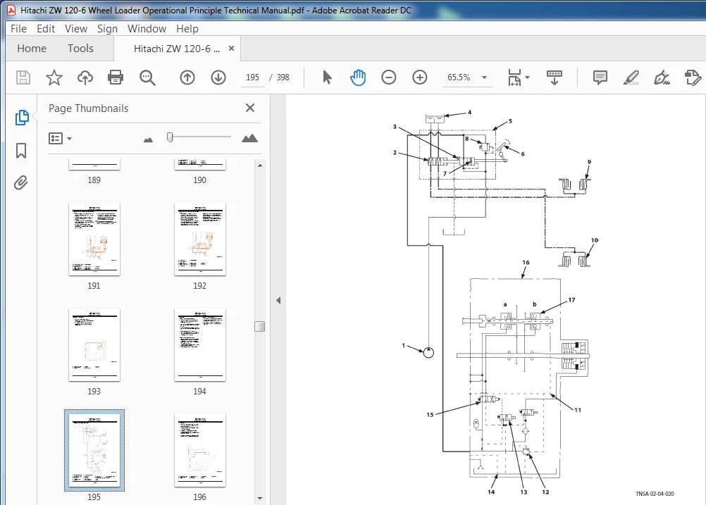
TONSA60-EN-00............................................................  1
	CONTENTS.............................................................  3
	INTRODUCTION.........................................................  9
		To The Reader....................................................  9
		Additional References............................................  9
		Manual Composition...............................................  9
		Page Number......................................................  9
		Trademark........................................................  9
		Safety Alert Symbol and Headline Notations....................... 10
		Units Used....................................................... 10
	SYMBOL AND ABBREVIATION.............................................. 11
		Symbol and Abbreviation.......................................... 11
	SECTION AND GROUP CONTENTS........................................... 13
	SECTION 1 GENERAL.................................................... 15
		Group 1 Specifications........................................... 17
			Specifications............................................... 17
		Group 2 Component Layout......................................... 19
			MAIN COMPONENT (OVERVIEW).................................... 19
			MAIN COMPONENT............................................... 21
			ELECTRICAL SYSTEM (OVERVIEW)................................. 23
			AIR CLEANER, RADIATOR, AND SURROUNDINGS...................... 24
			BATTERY BOX.................................................. 26
			FRAME: REAR RIGHT INSIDE..................................... 26
			HYDRAULIC OIL TANK........................................... 27
			FUEL TANK.................................................... 28
			CAB.......................................................... 29
			FRONT CONSOLE................................................ 30
			RIGHT CONSOLE................................................ 31
			REAR CONSOLE................................................. 32
			CONTROL UNIT................................................. 33
			ENGINE....................................................... 35
			AFTERTREATMENT DEVICE........................................ 36
			TRANSMISSION/HST MOTOR....................................... 37
			PUMP DEVICE.................................................. 38
			CONTROL VALVE................................................ 39
			PILOT Lock SOLENOID VALVE.................................... 40
			RIDE CONTROL VALVE........................................... 41
			DEF Tank..................................................... 42
			DEF SUPPLY MODULE............................................ 43
		Group 3 Component Specifications................................. 45
			Engine....................................................... 45
			Engine Accessories........................................... 49
			Hydraulic Component.......................................... 51
			Electrical Component......................................... 56
	SECTION 2 SYSTEM..................................................... 59
		Group 1 Controller............................................... 61
			OVERVIEW..................................................... 61
			CAN CIRCUIT.................................................. 62
		Group 2 Control System........................................... 65
			OVERVIEW..................................................... 65
			ENGINE CONTROL (ECM)......................................... 68
			HST PUMP/MOTOR, TRANSMISSION CONTROL......................... 83
			VALVE CONTROL................................................107
			OTHER CONTROL................................................111
			CONTROL BY ELECTRICAL AND HYDRAULIC COMBINED CIRCUIT.........115
		Group 3 Engine System............................................123
			OVERVIEW.....................................................123
			FUEL INJECTION CONTROL.......................................124
			FUEL INJECTION AMOUNT CORRECTION CONTROL.....................132
			EGR CONTROL..................................................134
			PREHEATING CONTROL...........................................136
			ALARM CONTROL................................................137
			UREA SCR SYSTEM..............................................139
			ENGINE OUTPUT RESTRICTION CONTROL (INDUCEMENT)...............154
			AFTERTREATMENT DEVICE........................................159
			AFTERTREATMENT DEVICE REGENERATION CONTROL...................161
		Group 4 Hydraulic System.........................................163
			OVERVIEW.....................................................163
			MAIN CIRCUIT.................................................164
			OVERVIEW.....................................................166
			STRUCTURE....................................................167
			OPERATION....................................................169
			HST CIRCUIT..................................................178
			PILOT CIRCUIT................................................186
			TRANSMISSION CIRCUIT.........................................193
			SERVICE BRAKE CIRCUIT........................................199
		Group 5 Electrical System........................................201
			OVERVIEW.....................................................201
			MAIN CIRCUIT.................................................202
			ELECTRIC POWER CIRCUIT (KEY SWITCH: OFF).....................204
			CAN CIRCUIT..................................................206
			ACCESSORY CIRCUIT (KEY SWITCH: ACC)..........................208
			STARTING CIRCUIT (KEY SWITCH: START).........................210
			CHARGING CIRCUIT (KEY SWITCH: ON)............................212
			SURGE VOLTAGE PREVENTION CIRCUIT.............................216
			LOCK CIRCUIT (KEY SWITCH: ON)................................218
			ENGINE STOP CIRCUIT..........................................220
			STEERING COLUMN BOX CIRCUIT..................................223
			HEADLIGHT CIRCUIT............................................224
			HAZARD LIGHT CIRCUIT (KEY SWITCH: OFF).......................230
			TURN SIGNAL LIGHT CIRCUIT....................................232
			HORN CIRCUIT (KEY SWITCH: OFF)...............................234
			BACK BUZZER, REVERSE LIGHT CIRCUIT...........................236
			BRAKE LIGHT CIRCUIT..........................................238
			PARKING BRAKE CIRCUIT........................................240
			ACCESSORY CIRCUIT............................................245
			WORK LIGHT CIRCUIT...........................................246
			WIPER CIRCUIT................................................248
			CAB LIGHT CIRCUIT............................................254
	SECTION 3 COMPONENT OPERATION........................................259
		Group 1 Pump Device..............................................261
			OVERVIEW.....................................................261
			ROTARY GROUP.................................................264
			DISPLACEMENT CYLINDER........................................266
			DA VALVE.....................................................270
			FORWARD/REVERSE SELECTOR CONTROL SOLENOID VALVE..............271
			CUTOFF VALVE.................................................273
			TRAVEL RELIEF VALVE..........................................275
			CHARGE RELIEF VALVE..........................................275
			HST CHARGE PUMP..............................................277
			MAIN PUMP, BRAKE/TRANSMISSION PUMP...........................278
		Group 2 Control Valve............................................281
			Overview.....................................................281
			Hydraulic Circuit............................................285
			Main Relief Valve............................................287
			Overload Relief Valve (with Make-Up Function)................289
			Make-Up Valve................................................295
		Group 4 Steering Valve...........................................299
			OVERVIEW.....................................................299
			STRUCTURE....................................................300
			OPERATION....................................................301
		Group 5 HST Motor................................................305
			OVERVIEW.....................................................305
			ROTARY GROUP.................................................307
			REGULATOR....................................................309
			MOTOR DISPLACEMENT ANGLE CONTROL.............................310
			MOTOR DISPLACEMENT ANGLE CONTROL SOLENOID VALVE..............310
			TRAVEL RESTRICTION SOLENOID VALVE............................314
			FLUSHING VALVE...............................................316
		Group 6 Pilot Valve..............................................319
			OVERVIEW (JOYSTICK TYPE PILOT VALVE FOR FRONT ATTACHMENT)....319
			OPERATION....................................................321
			ELECTROMAGNETIC DETENT.......................................328
		Group 8 Transmission.............................................329
			Outline......................................................329
			Transmission Part............................................331
			Travel Mode Selector Solenoid Valve Unit.....................338
			Accumulator..................................................342
			SOLENOID VALVE...............................................343
			Parking Brake................................................344
		Group 9 Axle.....................................................347
			OVERVIEW.....................................................347
			DIFFERENTIAL.................................................348
			TORQUE PROPORTIONING DIFFERENTIAL (TPD)......................352
			LIMITED SLIP DIFFERENTIAL (LSD) (OPTIONAL)...................354
			SERVICE BRAKE................................................356
			FINAL DRIVE / AXLE SHAFT.....................................358
		Group 10 Brake Valve.............................................359
			OVERVIEW.....................................................359
			STRUCTURE....................................................360
			OPERATION....................................................362
		Group 11 Priority Valve..........................................367
			OVERVIEW.....................................................367
			STRUCTURE....................................................368
			OPERATION....................................................370
		Group 12 Ride Control Valve......................................377
			Outline......................................................377
			Charge-Cut Spool.............................................382
			Overload Relief Valve........................................384
			Drain Plug...................................................388
		Group 13 Others..................................................389
			PROPELLER SHAFT..............................................389
			RIDE CONTROL ACCUMULATOR.....................................390
			INCHING VALVE................................................391
			PILOT SHUT-OFF SOLENOID VALVE................................392
			SOLENOID VALVE...............................................394
			FILTER.......................................................396
Please Note:
⦁ This is the SAME manual used by the dealers to troubleshoot any faults in your vehicle. This can be yours in 2 minutes after the payment is made.
⦁ Contact us at [email protected] should you have any queries before your purchase or that you need any other service / repair / parts operators manual.
Nicolas Damari –
Very good service