★ TRUSTED BY 321,897+ PROFESSIONALS WORLDWIDE
🏒
Trusted Business
Verified & Licensed
πŸ›‘οΈ
Virus Free Files
100% Safe Downloads
πŸ”’
Secure Payment
SSL Protected
⚑
Instant Delivery
Available Immediately
Sale!

Hitachi ZW220 ZW250 Wheel Loader Troubleshooting Manual TT4GB-E PDF

Original price was: $44.95.Current price is: $27.95.

Hitachi ZW220 and ZW250 wheel loader troubleshooting manual TT4GB-E in PDF – fault code diagnosis, operational performance tests, Dr.ZX procedures, component layouts and electrical system inspection for both models.

SKU: hitachi-zw220-zw250-troubleshooting-tt4gbe Category: Tags: , , , Vendor: Electrical Service Docs
⚑
Instant PDF Download
Available immediately
πŸ’Ύ
Save to Your Device
Download & keep forever
πŸ›‘οΈ
Antivirus Scanned
100% virus-free
🌍
Trusted Worldwide
175,000+ customers

Description

Hitachi ZW220 ZW250 Wheel Loader Troubleshooting Manual

The Hitachi ZW220 ZW250 Wheel Loader Troubleshooting Manual TT4GB-E is the dedicated fault-finding and performance-testing volume from Hitachi Construction Machinery for these two wheel loader models. It is written for the experienced technician rather than the casual reader – each group assumes you already know how the machine is supposed to behave and want the measured value, the fault code path, the flow chart decision, or the adjustment procedure that converts a symptom into a repair. Where the operational principle volume explains what a system is designed to do, this manual is the one you open when the machine is not doing it.

Both the ZW220 and the ZW250 share this single troubleshooting book. Standard performance tables, main pump P-Q curves, sensor activating ranges and pressure settings are printed separately for each model, so you are never reading ZW220 numbers and applying them to a ZW250 by mistake.

File Details

  • Manual type: Technical Manual (Troubleshooting)
  • Brand: Hitachi Construction Machinery Co. Ltd.
  • Covered models: ZW220, ZW250 wheel loaders (ZW310 appears in the wiring appendix)
  • Volume / publication reference: TT4GB-E (Troubleshooting)
  • Language: English
  • File format: PDF
  • Page count: 597 pages
  • Sections: Section 4 Operational Performance Test and Section 5 Troubleshooting, plus references to the Technical Manual (Operational Principle) and Workshop Manual

Chapters Covered

  • Section 4 – Operational Performance Test
    • Group 1 Introduction – operational performance tests, preparation
    • Group 2 Standard – performance standard tables for ZW220 and ZW250, main pump P-Q curves, sensor activating range
    • Group 3 Engine Test – engine speed, engine compression pressure, valve clearance adjustment, lubricant consumption
    • Group 4 Wheel Loader Test – travel speed, service brake function and wear, parking brake function, bucket and bell crank stopper clearances, hydraulic cylinder cycle time, cylinder drift, bucket levelness, control lever operating force and stroke
    • Group 5 Component Test – primary and secondary pilot pressure, solenoid valve set pressure, main pump delivery pressure, main relief valve, steering relief, overload relief, main pump flow rate, regulator adjustment, service brake and parking brake pressure, brake accumulator, brake warning pressures, transmission clutch pressure, torque converter pressure
    • Group 6 Adjustment – transmission learning, lift arm angle sensor learning, drive belt tension
  • Section 5 – Troubleshooting
    • Group 1 Diagnosing Procedure – procedure, monitor service mode operation and display list
    • Group 2 Dr.ZX – self-diagnostic results, controller selection, main controller, engine controller, ICF controller, monitor unit, TCU controller
    • Group 3 e-Wheel – daily report data, frequency distribution data, total operating hours, alarm list, failure list, data download/upload, ICF fault codes, satellite terminal fault codes
    • Group 4 Component Layout – main component layouts, travel system, cab electrical, engine and fan pump, pump device, drive unit, control valve, ride control, charging block, fan motor, parking brake solenoid, steering valve, emergency steering pump, transmission views
    • Group 5 Troubleshooting A – MC, ECM, TCU, ICF, satellite terminal and monitor unit fault code lists with CAN harness checks and terminal reference tables
    • Group 6 Troubleshooting B – symptom-driven diagnosis for engine, front attachment, travel, brake and steering systems, exchange inspection, brake air bleeding
    • Group 7 Troubleshooting C – monitor indicator, gauge and buzzer diagnosis
    • Group 8 Electrical System Inspection – connector handling, fuse and fusible link inspection, battery voltage, alternator check, continuity, voltage and current measurement, false-signal checks

Because the TT4GB-E opens with a complete operational performance test section before it moves into fault diagnosis, the two halves of the book work together rather than sitting apart. You can establish a baseline – travel speed, brake stopping distance, cylinder cycle times, relief pressures, pilot pressures – then use the fault-code and symptom-driven troubleshooting groups to close the gap between what the machine actually does and what the standard table says it should. Each controller section carries its own fault code list, the CAN harness checks are laid out connector-by-connector with terminal numbers, and the electrical inspection group at the back gives you the practical groundwork of fuse, fusible link, continuity and false-signal testing that most electrical faults are actually solved with.

Operational Performance Testing for the ZW220 and ZW250

The performance test section is where the troubleshooting manual earns its keep in a workshop. Every test has preparation, measurement, evaluation and remedy written against it, and the standard tables give you the allowable bands for each model side by side. For the ZW220 the table lists slow idle speed of 840 plus or minus 25 min-1, fast idle of 2240 or 2330 plus or minus 25 min-1 depending on fan specification, and the four travel speed ranges for each gear. For the ZW250 the fast idle figures and travel speeds are printed separately.

Hydraulic testing is covered in the same level of detail: main pump delivery pressure in neutral, main relief valve pressure for lift arm and bucket relief operation, steering relief pressure, overload relief reference values at 50 L/min, and the full main pump P-Q curve with points A through D for both models. There are pressure check port photographs and schematics for each measurement so you are not guessing where a gauge goes.

Complete PDF Bookmark Tree

Complete Bookmarks

The complete bookmarks in the β€œHitachi ZW220 ZW250 Wheel Loader Troubleshooting Manual TT4GB-E PDF” are as follows:

ZW220/250_TT4GB-E-00p. 1
INTRODUCTIONp. 2
SECTION AND GROUPCONTENTSp. 4
SAFETYp. 6
RECOGNIZE SAFETY INFORMATIONp. 6
UNDERSTAND SIGNAL WORDSp. 6
FOLLOW SAFETY INSTRUCTIONSp. 7
PREPARE FOR EMERGENCIESp. 7
WEAR PROTECTIVE CLOTHINGp. 8
PROTECT AGAINST NOISEp. 8
NSPECT MACHINEp. 8
GENERAL PRECAUTIONS FOR CABp. 9
USE HANDHOLDS AND STEPSp. 10
ADJUST THE OPERATOR'S SEATp. 10
ENSURE SAFETY BEFORE RISING FROMOR LEAVING OPERATOR’S SEATp. 10
FASTEN YOUR SEAT BELTp. 11
MOVE AND OPERATE MACHINE SAFELYp. 11
HANDLE STARTING AIDS SAFELYp. 11
OPERATE ONLY FROM OPERATOR'SSEATp. 12
JUMP STARTINGp. 12
INVESTIGATE JOB SITE BEFOREHANDp. 13
EQUIPMENT OF HEAD GUARD, ROPS,FOPSp. 14
PROVIDE SIGNALS FOR JOBS INVOLVINGMULTIPLE NUMBERS OF MACHINESp. 14
KEEP RIDERS OFF MACHINEp. 15
DRIVE SAFELYp. 15
DRIVE MACHINE SAFELY (WORK SITE)p. 15
DRIVE SAFELY WITH BUCKET LOADEDp. 16
DRIVE ON SNOW SAFELYp. 16
TRAVEL ON PUBLIC ROADS SAFELYp. 16
AVOID INJURY FROM ROLLAWAY ACCIDENTSp. 17
AVOID ACCIDENTS FROM BACKING UPAND TURNINGp. 18
AVOID POSITIONING BUCKET OVERANYONEp. 19
AVOID TIPPINGp. 19
NEVER UNDERCUT A HIGH BANKp. 20
DIG WITH CAUTIONp. 20
PERFORM TRUCK LOADING SAFELYp. 20
AVOID POWER LINESp. 21
PRECAUTIONS FOR OPERATIONp. 21
PRECAUTIONS FOR LIGHTENINGp. 21
OBJECT HANDLINGp. 21
PROTECT AGAINST FLYING DEBRISp. 22
PARK MACHINE SAFELYp. 22
STORE ATTACHMENTS SAFELYp. 23
TRANSPORT SAFELYp. 23
HANDLE FLUIDS SAFELY-AVOID FIRESp. 24
PRACTICE SAFE MAINTENANCEp. 25
WARN OTHERS OF SERVICE WORKp. 26
SUPPORT MACHINE PROPERLYp. 26
STAY CLEAR OF MOVING PARTSp. 26
SUPPORT MAINTENANCE PROPERLYp. 27
PREVENT PARTS FROM FLYINGp. 27
PREVENT BURNSp. 28
REPLACE RUBBER HOSES PERIODICALLYp. 28
PREVENT FIRESp. 30
EVACUATING IN CASE OF FIREp. 31
BEWARE OF EXHAUST FUMESp. 31
PRECAUTIONS FOR WELDING ANDGRINDINGp. 31
AVOID HEATING NEAR PRESSURIZEDFLUID LINESp. 32
AVOID APPLYING HEAT TO LINES CONTAININGFLAMMABLE FLUIDSp. 32
REMOVE PAINT BEFORE WELDING ORHEATINGp. 32
BEWARE OF ASBESTOS DUSTp. 33
PREVENT BATTERY EXPLOSIONSp. 33
SERVICE AIR CONDITIONING SYSTEMSAFELYp. 33
HANDLE CHEMICAL PRODUCTS SAFELYp. 34
DISPOSE OF WASTE PROPERLYp. 34
BEFORE RETURNING THE MACHINE TOTHE CUSTOMERp. 35
SECTION 4OPERATIONALPERFORMANCE TESTp. 36
Group 1 Introductionp. 38
Operational Performance Testsp. 38
Preparation for Performance Testsp. 39
Group 2 Standardp. 40
Operational PerformanceStandard Tablep. 40
Main Pump P-Q Curvep. 50
Sensor Activating Rangep. 52
Group 3 Engine Testp. 54
Engine Speedp. 54
Engine Compression Pressurep. 56
Valve Clearance Adjustmentp. 57
Lubricant Consumptionp. 60
Group 4 Wheel Loader Testp. 62
Travel Speedp. 62
Service Brake Function Checkp. 63
Service Brake Wear Amountp. 64
Parking Brake Function Checkp. 65
Bucket and Bell Crank StopperClearancesp. 67
Hydraulic Cylinder Cycle Timep. 69
Cylinder Drift Checkp. 71
Bucket Levelnessp. 72
Control Lever Operating Forcep. 73
Control Lever Strokep. 74
Group 5 Component Testp. 76
Primary Pilot Pressurep. 76
Secondary Pilot Pressurep. 78
Solenoid Valve Set Pressurep. 79
Main Pump Delivery Pressurep. 81
Main Relief Valve Set Pressurep. 83
Steering Relief Pressurep. 87
Overload Relief Valve Set Pressurep. 89
Main Pump Flow Ratep. 91
Regulator Adjustmentp. 95
Service Brake Pressure (Front and Rear)p. 97
Parking Brake Pressurep. 99
Brake Accumulated Pressurep. 101
Brake Warning Set Pressure (Decrease)p. 103
Brake Warning Set Pressure (Increase)p. 105
Transmission Clutch Pressurep. 107
Torque Converter Pressure(Inlet and Outlet)p. 109
Group 6 Adjustmentp. 112
Transmission Learningp. 112
Lift Arm Angle SensorLearning (Optional)p. 117
Drive Belt Tension Adjustmentp. 119
SECTION 5TROUBLESHOOTINGp. 122
Group 1 Diagnosing Procedurep. 126
Introductionp. 126
Diagnosing Procedurep. 127
How to Operate Service Made ofMonitorp. 131
Display List of Monitor Service Modep. 132
Group 2 Dr.ZXp. 134
Outlinep. 134
Operationp. 135
Self-Diagnosing Resultp. 137
Select Controllerp. 139
Main Controllerp. 140
Main Menu Monitor Display (MainController)p. 141
Setting (Main Controller)p. 145
Record Data Display (Main Controller)p. 152
Password Change (Main Controller)p. 153
Engine Controllerp. 154
Monitor Display (Engine Controller)p. 155
Recorded Data Display (EngineController)p. 159
Password Change (Engine Controller)ICF Controllerp. 160
ICF Various Setup (ICF Controller)p. 162
Save Data Check (ICF Controller)p. 173
Password Change (ICF Controller)p. 174
Monitor Unitp. 176
Monitoring (Monitor Unit)p. 177
Various Settings (Monitor Unit)p. 179
Internal Hour Meter Synchronizationp. 180
Password Change (Monitor Unit)p. 181
TCU Controllerp. 182
Monitor Display (TCU Controller)p. 183
Recorded Data Display (TCU Controller)p. 187
Password Change (TCU Controller)p. 188
Group 3 e-Wheelp. 190
Outlinep. 190
List of Daily Report Datap. 191
List of Frequency Distribution Datap. 192
List of Total Operationg Hoursp. 193
List of Alarmp. 194
List of failurep. 195
How to Download and Upload Data ofICFp. 196
Various Setup if ICF and SatelliteCommunication Terminal by UsingDr.ZXp. 199
List of ICF Fault Codep. 211
List of Fault Code of SattelliteCommunication Terminalp. 212
Group 4 Component Layoutp. 216
Main Component Layout (Overview)p. 216
Main Component Layout (Upper- structure)p. 217
Main Component Layout (TravelSystem)p. 218
Electric Component Layout (Overview)p. 219
Electrical System (Cab)p. 220
Engine and Fan Pumpp. 225
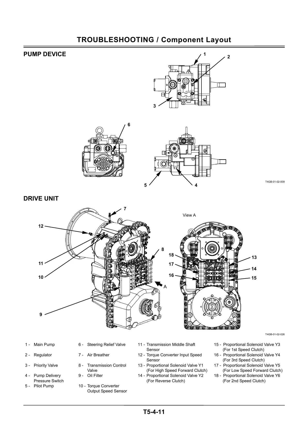
Pump Device, Drive Unitp. 226
Control Valvep. 227
Ride Control Valve ,Charging Block,Fan Motor, Parking Brake SolenoidValvep. 228
Steering Valve, EmergencySteering Pumpp. 229
Components in Control Valvep. 231
Components in Steering Valvep. 243
Components in Charging Blockp. 247
Components in Ride Control Valvep. 253
Side View of Transmissionp. 257
Front View of Transmissionp. 258
Pressure Sensor Ports ofTransmissionp. 259
Cross-Sectional Drawing ofTransmissionp. 260
Cross-Sectional Drawing of TorqueConverterp. 261
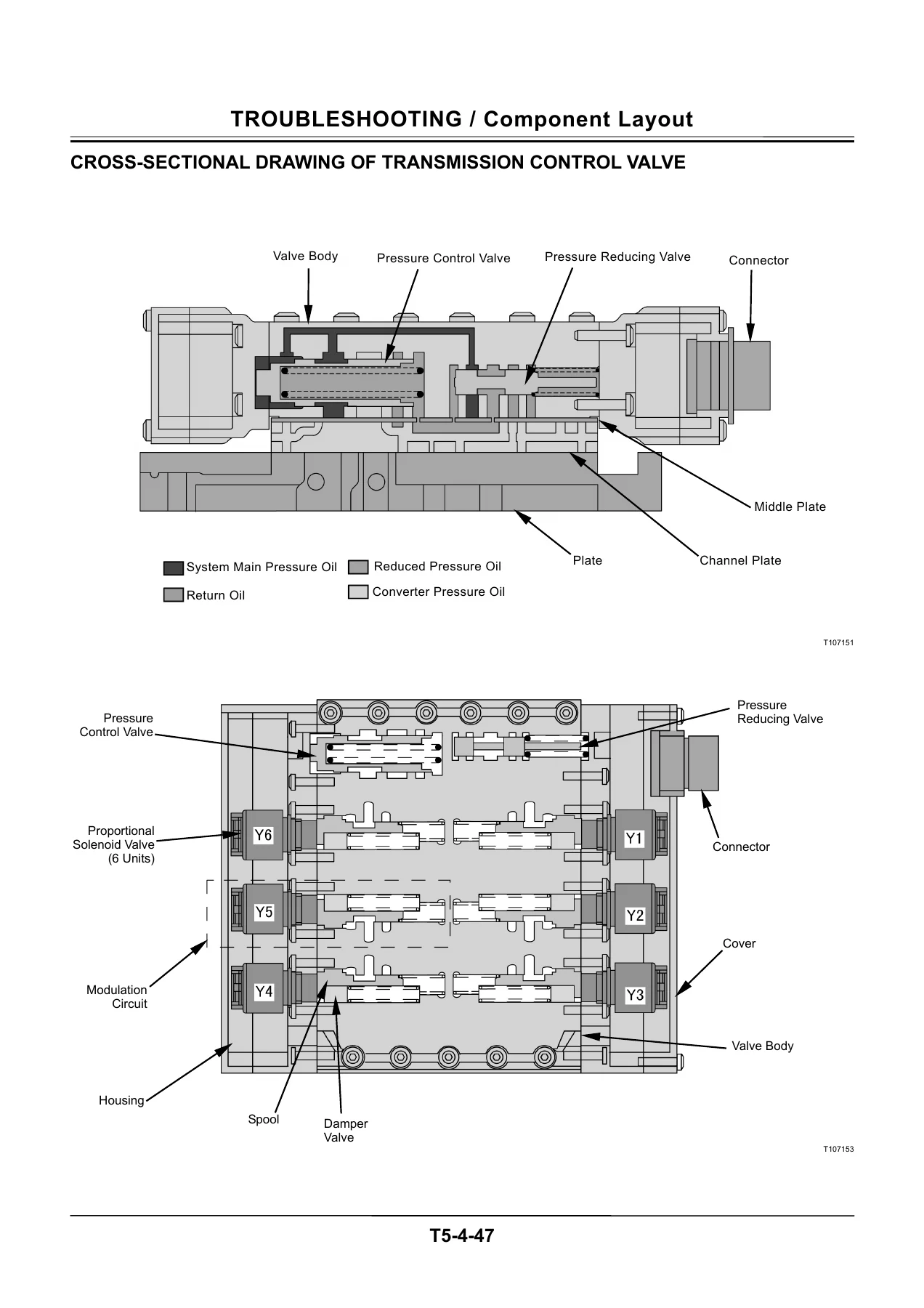
Cross-Sectional Drawing ofTransmission Control Valvep. 262
Circuit of Drive Unitp. 263
Group 5 Troubleshooting Ap. 264
Troubleshooting A Procedurep. 264
MC Fault Code Listp. 265
ECM Fault Code Listp. 279
TCU Fault Code Listp. 303
ICF Fault Code Listp. 321
Satellite Terminal Fault Code Listp. 323
Monitor Unit Fault Code Listp. 325
Controller Hardware FailureMC Fault Codes 11000 to 11002p. 326
MC Fault Code 11003p. 327
MC Fault Code 11004p. 328
CAN Harness Checkp. 329
Engine FailureMC Fault Code 11103p. 354
Pump FailureMC Fault Code 11204p. 355
MC Fault Code 11209p. 356
Pilot FailureMC Fault Code 11313p. 357
Proportional Solenoid Valve FailureMC Fault Code 11412p. 358
MC Fault Code 11413p. 359
CAN Data Reception FailureMC Fault Codes 11910, 11920p. 360
CAN Harness Check(MC Fault Codes 11910, 11920)p. 361
MC Fault Code 11914p. 364
CAN Harness Check(MC Fault Code 11914)p. 365
MC Fault Codes 11912, 11913,11916, 11917p. 368
CAN Harness Check(MC Fault Codes 11912, 11913,11916, 11917)p. 369
Other FailuresMC Fault Code 11901p. 372
Proportional Solenoid Valve TrubleCheckp. 373
ECM, Sensor SystemECM Fault Codes 100, 102, 105, 108,110, 157, 172p. 376
ECM Fault Codes 174, 636, 723,10001p. 377
ECM, External Device SystemECM Fault Codes 651, 652, 653, 654,655, 656, 1347, 10002p. 378
ECM, Fuel SystemECM Fault Codes 157, 633, 1239,1240p. 379
ECM, Engine ProtectionECM Fault Codes 110, 190p. 380
ECM, External Circuit SystemECM Fault Codes 987, 1485p. 381
ECM, Internal Circuit SystemECM Fault Codes 628, 1077, 1079,1080, 10003, 10004, 10005p. 382
ECM Fault Codes 10006, 10007,10008, 10009, 10010, 10011, 10013p. 383
ECM, Communication SystemECM Fault Codes 639p. 384
Role and Connection of EachTerminal in TCUp. 385
ICF, Satellite Terminal Fault Codes14000 to 14003p. 388
ICF, Satellite Terminal Fault Codes14006, 14008, 14100 to 14106p. 392
Monitor Unit Fault Codes 13306,13308p. 394
Monitor Unit Fault Code 13312p. 395
Monitor Unit Fault Code 13314p. 396
Group 6 Troubleshooting Bp. 398
Troubleshooting B Procedurep. 398
Relationship between Machine TroubleSymptoms and Related Partsp. 399
Correlation between TroubleSymptoms and Part Failuresp. 415
Engine System Troubleshootingp. 429
Front Attachment SystemTroubleshootingp. 438
Travel System Troubleshootingp. 457
Brake System Troubleshootingp. 473
Steering System Troubleshootingp. 481
Other System Troubleshootingp. 484
Exchange Inspectionp. 506
Bleeding Air from Brake (Axle)p. 508
One Part of Data, β€œDaily ReportData”, β€œDistribution Data”, β€œTotalOperationg Hours” and β€œAlarm” isNot Recordedp. 509
Group 7 Troubleshooting Cp. 524
Troubleshooting C (Trouble Shootingfor Monitor) Procedurep. 524
Malfunction of Indicator Light CheckSystemp. 525
Malfunction of Buzzer in Monitorp. 527
Malfunction of Coolant TemperatureGaugep. 529
Malfunction of Transmission OilTemperature Gaugep. 531
Malfunction of Fuel Gaugep. 533
Malfunction of Turn Signal Indicators(Left and Right)p. 535
Malfunction of Hazard Light Indicatorp. 536
Malfunction of High Beam Indicatorp. 537
Malfunction of Working Light Indicatorp. 539
Malfunction of Forward/ReverseSwitch Indicatorp. 541
Malfunction of Maintenance Indicatorp. 543
Malfunction of Preheat Indicatorp. 544
Malfunction of Transmission OilTemperaturep. 545
Malfunction of Hydraulic OilTemperature Indicatorp. 547
Malfunction of Transmission WarningIndicatorp. 549
Malfunction of Air Filter RestrictionIndicatorp. 551
Malfunction of Engine Oil PressureIndicatorp. 553
Malfunction of Overheat Indicatorp. 555
Malfunction of Engine WarningIndicatorp. 557
Malfunction of Stop Indicatorp. 558
Malfunction of Service Indicatorp. 559
Malfunction of Parking Brake Indicatorp. 561
Malfunction of Clearance LightIndicatorp. 563
Malfunction of Brake Low Oil PressureIndicatorp. 564
Malfunction of Brake Low Oil LevelIndicatorp. 565
Malfunction of Emergency SteeringIndicator (Optional)p. 567
Malfunction of Low Steering OilPressure Indicator (Optional)p. 569
Malfunction of Discharge WarningIndicatorp. 571
Malfunction of Monitor Displayp. 573
Malfunction of Ride Control Indicatorp. 574
Malfunction of Engine CoolantTemperature Displayp. 575
Group 8 Electrical System Inspectionp. 576
Precautions for Inspection andMaintenancep. 576
Instructions for DisconnectingConnectorsp. 578
Fuse Inspectionp. 581
Fusible Link Inspectionp. 583
Battery Voltage Checkp. 584
Alternator Checkp. 585
Continuity Checkp. 587
Voltage and Current Measurementp. 589
Check by False Signalp. 592
SERVICE MANUAL REVISION REQUEST FORMp. 596
THE ATTACHED DIAGRAM LISTp. 597

Fault Code and Dr.ZX Diagnosis

The troubleshooting groups cover fault code diagnosis for every controller on the machine – MC, ECM, TCU, ICF, the satellite communication terminal and the monitor unit. Each fault code entry pairs the code with the trouble description, the likely cause, the affected control, the expected machine behaviour when the fault is active, and the repair procedure. Fault codes are also translated to their equivalent engine fault codes and, where relevant, to a cross-referenced page in the engine manual. The CAN harness checks that follow are built as step-by-step flow charts with connector pinouts shown harness-end, so an open or shorted CAN line can be isolated methodically rather than by substitution.

Dr.ZX and Monitor Service Mode Procedures

The manual includes the full menu tree for Dr.ZX operation on this machine: connecting Dr.ZX to the diagnosing connector in the cab, selecting the controller, displaying monitor items, recording data to a data bank, changing parameters such as requested engine speed and warm-up speed, and reading or regenerating recorded data for each controller. Instructions for starting the monitor unit in service mode and reading the display order – model, clock, hour meter, fuel consumption, hydraulic and transmission oil life, odometer, engine speed, coolant temperature, transmission oil temperature, hydraulic oil temperature, and fault code – are given as well.

Component Layouts, Wiring and Circuit References

Group 4 of Section 5 is a reference gallery that many technicians end up using more than the flow charts. It shows where the main components actually sit on the machine – overview, upperstructure, travel system, cab electrical, engine and fan pump, pump device, drive unit, control valve, ride control valve, charging block, fan motor, parking brake solenoid valve, steering valve, emergency steering pump, transmission side view, front view, pressure sensor ports, cross-sections, and the transmission control valve. The manual’s attached diagram list also names the electrical circuit diagrams and hydraulic circuit diagrams that accompany the ZW220 and ZW250 (EU standard and general standard variants), covering the front, centre, front console, side console, rear console, transmission, rear frame and engine harnesses.

Why This Troubleshooting Manual Matters in the Workshop

Wheel loader faults are rarely as simple as a worn part. The same symptom – a slow front attachment, a machine that will not travel, a brake that feels soft – can trace back to a pump regulator adjustment, a proportional solenoid, a faulty CAN line, a pressure sensor, or a mechanical failure in the transmission. Guessing at it costs time and parts. The TT4GB-E gives the technician the instruments of diagnosis: which pressure to check, what it should read, what code the controller has stored, which harness pin to test, and which adjustment to make. It also gives the sequence – performance test first, diagnosis second, then remedy – that keeps the work orderly rather than reactive.

Get the TT4GB-E PDF

IMAGES PREVIEW

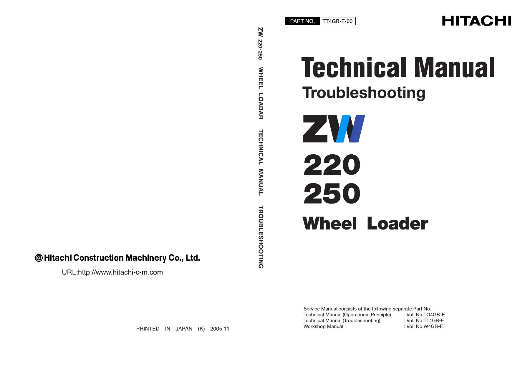
Hitachi ZW220 ZW250 Wheel Loader Troubleshooting Manual TT4GB-E PDF β€” PDF page 1 preview
Hitachi ZW220 ZW250 Wheel Loader Troubleshooting Manual TT4GB-E PDF β€” PDF page 226 preview
Hitachi ZW220 ZW250 Wheel Loader Troubleshooting Manual TT4GB-E PDF β€” PDF page 262 preview

This Hitachi ZW220 ZW250 Wheel Loader Troubleshooting Manual is delivered as an instant-download PDF – no shipping, no waiting for a physical book, no risk of a missing volume. Open it in any PDF reader on a workshop laptop, tablet or phone, print the pages you need for the job at hand, and keep the full 597-page reference on file for the next fault. Whether you are servicing a ZW220 or a ZW250, chasing a specific fault code or building a baseline performance record, this is the troubleshooting reference the machine was designed to be diagnosed with.
Reviews

There are no reviews yet.

Be the first to review “Hitachi ZW220 ZW250 Wheel Loader Troubleshooting Manual TT4GB-E PDF”

What Our Customers Say

β˜…β˜…β˜…β˜…β˜… Live reviews from customers
Loading customer reviews...
0
    0
    Your Cart
    Your cart is emptyReturn to Shop
    πŸ›’
    Recently Purchased
    πŸ•’ verified order