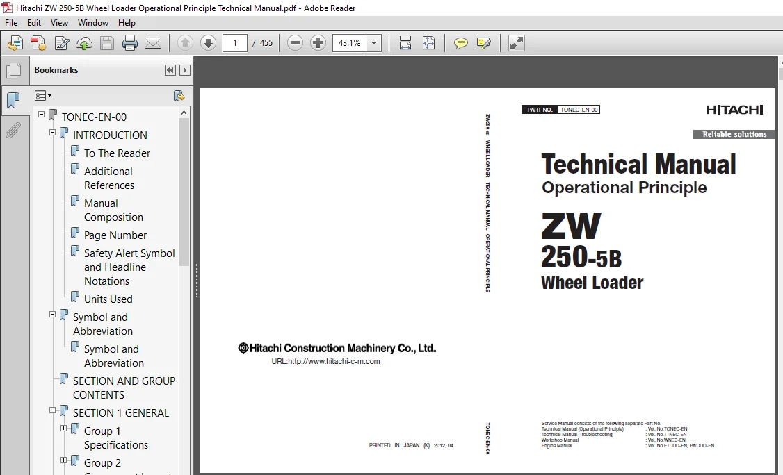
Hitachi ZW250-5B Wheel Loader Operational Principle Technical Manual (TONEC-EN-00) – PDF Download
Original price was: $79.95.$27.95Current price is: $27.95.
- Hitachi ZW250-5B Wheel Loader Operational Principle Technical Manual
- Part No:TONEC-EN-00
Description
Hitachi ZW250-5B Wheel Loader Operational Principle Technical Manual (TONEC-EN-00)
File Details:
Hitachi ZW250-5B Wheel Loader Operational Principle Technical Manual (TONEC-EN-00)
- Manual Language:English
- Pages:455
- Size: 11.4 MB
- Downloadable:Yes
- Format:PDF
HITACHI ZW250-5B WHEEL LOADER OPERATIONAL PRINCIPLE TECHNICAL MANUAL (TONEC-EN-00) – PDF DOWNLOAD:
Image Preview:
Description:
Hitachi ZW250-5B Wheel Loader Operational Principle Technical Manual (TONEC-EN-00)
To The Reader
This manual is written for an experienced technician to provide technical information needed to maintain and repair this machine.
Be sure to thoroughly read this manual for correct product information and service procedures.
If you have any questions or comments, at if you found any errors regarding the contents of this manual, please contact using “Service Manual Revision Request Form” at the end of this manual.
Additional References
Please refer to the other materials (operator’s manual, parts catalog, engine technical material and Hitachi training material etc.) in addition to this manual.
Manual Composition
This manual consists the Technical Manual, the Workshop Manual and the Engine Manual.
Information included in the Technical Manual: Technical information needed for redelivery and delivery, operation and activation of all devices and systems, operational performance tests, and troubleshooting procedures.
Information included in the Workshop Manual: Technical information needed for maintenance and repair of the machine, tools and devices needed for maintenance and repair, maintenance standards, and removal / installation and assemble / disassemble procedures.
Information included in the Engine Manual: Technical information needed for redelivery and delivery and maintenance and repair of the machine, operation and activation of all devices and systems, troubleshooting and assemble / disassemble procedures.
Table Of Contents:
Hitachi ZW250-5B Wheel Loader Operational Principle Technical Manual (TONEC-EN-00)
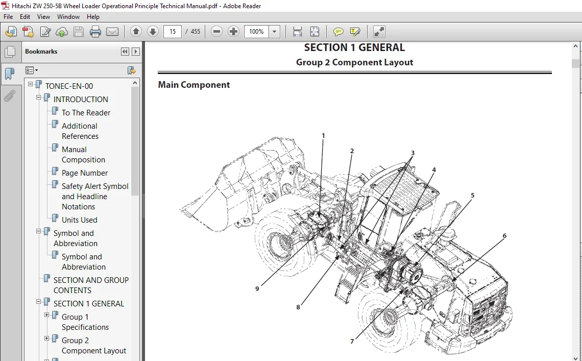
TONEC-EN-00..................................................................................................  1
	INTRODUCTION.............................................................................................  3
		To The Reader........................................................................................  3
		Additional References................................................................................  3
		Manual Composition...................................................................................  3
		Page Number..........................................................................................  3
		Safety Alert Symbol and Headline Notations...........................................................  4
		Units Used...........................................................................................  4
	Symbol and Abbreviation..................................................................................  5
		Symbol and Abbreviation..............................................................................  5
	SECTION AND GROUP CONTENTS...............................................................................  7
	SECTION 1 GENERAL........................................................................................  9
		Group 1 Specifications............................................................................... 11
			Specifications................................................................................... 11
		Group 2 Component Layout............................................................................. 13
			Main Component (Overview)........................................................................ 13
			Main Component................................................................................... 14
			Main Component................................................................................... 15
			Electric Component Layout (Overview)............................................................. 16
			Electrical System (Cab).......................................................................... 17
			Engine and Fan Pump.............................................................................. 25
			Pump Device...................................................................................... 27
			Drive Unit....................................................................................... 27
			Control Valve.................................................................................... 28
			Manifold Valve................................................................................... 29
			Brake Charge Valve............................................................................... 29
			Parking Brake Solenoid Valve..................................................................... 29
			3-Spool Solenoid Valve Unit...................................................................... 29
			Steering Valve................................................................................... 30
			Flow Regulator Valve............................................................................. 30
			Emergency Steering Pump.......................................................................... 30
		Group 3 Component Specifications..................................................................... 31
			Engine........................................................................................... 31
			Engine Accessories............................................................................... 35
			Hydraulic Component.............................................................................. 37
			Electrical Component............................................................................. 42
	SECTION 2 SYSTEM......................................................................................... 47
		Group 1 Controller................................................................................... 49
			Outline.......................................................................................... 49
			CAN Circuit...................................................................................... 50
		Group 2 Control System............................................................................... 53
			Outline.......................................................................................... 53
			Engine Control................................................................................... 56
			Pump Control..................................................................................... 85
			Transmission Control............................................................................. 90
			Fan Control, Valve Control.......................................................................109
			Control by Electric and Hydraulic Combined Circuit...............................................145
		Group 3 ECM System...................................................................................151
			Outline..........................................................................................151
			Fuel Injection Control...........................................................................152
			Fuel Injection Amount Correction Control.........................................................160
			EGR Control......................................................................................162
			Preheating Control...............................................................................164
			Alarm Control....................................................................................165
			Muffler Filter...................................................................................166
			Operation........................................................................................167
			Muffler Filter Regenerative Control..............................................................168
			Variable Turbocharger Control....................................................................170
		Group 4 Hydraulic System.............................................................................171
			Outline..........................................................................................171
			Pilot Circuit....................................................................................172
			Parallel Circuit Flow Rate Control...............................................................204
			Main Circuit.....................................................................................208
			Fan Circuit......................................................................................222
			Emergency Steering Circuit (Optional) (Refer to Control System / Emergency Steering Control.)....224
		Group 5 Electrical System............................................................................227
			Outline..........................................................................................227
			Main Circuit.....................................................................................228
			Electric Power Circuit (Key Switch: OFF).........................................................230
			CAN Circuit......................................................................................232
			Accessory Circuit (Key Switch: ACC)..............................................................234
			Starting Circuit (Key Switch: START).............................................................236
			Neutral Engine Start Circuit.....................................................................238
			Charging Circuit (Key Switch: ON)................................................................240
			Surge Voltage Prevention Circuit.................................................................244
			Pilot Shut-Off Circuit (Key Switch: ON)..........................................................246
			Auto Shut-Down Circuit (Optional)................................................................248
			Engine Stop Circuit..............................................................................250
			Monitor Circuit..................................................................................253
			Air Conditioner Circuit..........................................................................254
			Steering Column Monitor Circuit..................................................................257
			Head Light Circuit...............................................................................258
			Hazard Light Circuit (Key Switch: OFF)...........................................................264
			Turn Signal Light Circuit:.......................................................................266
			Horn Circuit (Key Switch: OFF)...................................................................268
			Reverse Light/Reverse Buzzer Circuit.............................................................270
			Brake Light Circuit..............................................................................272
			Parking Brake Circuit............................................................................274
			Accessory Circuit................................................................................279
			Work Light Circuit...............................................................................280
			Wiper Circuit....................................................................................282
			Cab Light Circuit................................................................................288
	SECTION 3 COMPONENT OPERATION............................................................................293
		Group 1 Pump Device..................................................................................295
			Outline..........................................................................................295
			Main Pump........................................................................................296
			Regulator........................................................................................298
			Priority Valve...................................................................................314
			Steering Main Relief Valve.......................................................................315
			Pilot Pump.......................................................................................316
			Pump Delivery Pressure Sensor....................................................................316
		Group 2 Control Valve................................................................................317
			Outline..........................................................................................317
			Hydraulic Circuit................................................................................324
			Main Relief Valve................................................................................328
			Overload Relief Valve (with Make-Up Function)....................................................330
			Anti-Drift Valve.................................................................................334
			Flow Rate Control Valve..........................................................................338
			Ride Control.....................................................................................342
			Ride Control Accumulator.........................................................................346
			Drain Plug.......................................................................................347
			Pump Control Valve...............................................................................348
		Group 3 Cooling Fan System...........................................................................351
			Fan Pump.........................................................................................351
			Fan Motor........................................................................................352
			Fan Valve........................................................................................353
		Group 4 Steering Pilot Valve.........................................................................361
			Outline..........................................................................................361
			Structure........................................................................................362
			Operation........................................................................................363
		Group 5 Steering Valve...............................................................................367
			Outline..........................................................................................367
			Operation........................................................................................370
			Steering Overload Relief Valve...................................................................372
		Group 6 Pilot Valve..................................................................................375
			Outline (Fingertip Control Type Pilot Valve for Front Attachment)................................375
			Operation........................................................................................376
			Electromagnetic Detent...........................................................................380
			Outline (Joystick Type Pilot Valve for Front Attachment).........................................381
			Operation........................................................................................383
			Electromagnetic Detent...........................................................................390
		Group 7 Charging Circuit.............................................................................391
			Outline..........................................................................................391
			Brake Charge Valve...............................................................................392
			Manifold Valve...................................................................................397
			Pilot Relief Valve...............................................................................398
			Torque Control Solenoid Valve / Front Control Lever Lock Solenoid Valve..........................399
			Service Brake Accumulator........................................................................400
			Pilot Accumulator................................................................................401
		Group 8 Drive Unit...................................................................................403
			Outline..........................................................................................403
			Torque Converter.................................................................................408
			Transmission.....................................................................................410
			Operation of Transmission........................................................................412
			Transmission Control Valve.......................................................................418
			Drive Unit Circuit...............................................................................420
		Group 9 Axle.........................................................................................421
			Outline..........................................................................................421
			Differential.....................................................................................422
			Torque Proportioning Differential (TPD)..........................................................426
			Limited Slip Differential (LSD) (Optional).......................................................428
			Service Brake....................................................................................430
			Final Drive / Axle Shaft.........................................................................432
		Group 10 Brake Valve.................................................................................433
			Outline..........................................................................................433
			Operation........................................................................................436
		Group 11 Others......................................................................................443
			Solenoid Valve...................................................................................443
			Flow Regulator Valve.............................................................................445
			Propeller Shaft..................................................................................446
			Torque Converter Cooler Check Valve..............................................................447
			Parking Brake Solenoid Valve.....................................................................448
			Emergency Steering Check Block...................................................................450
			Emergency Steering Pump..........................................................................451
	SERVICE MANUAL REVISION REQUEST FORM.....................................................................455
Please Note:
⦁ This is not a physical manual but a digital manual – meaning no physical copy will be couriered to you. The manual can be yours in the next 2 mins as once you make the payment, you will be directed to the download page IMMEDIATELY.
⦁ This is the same manual used by the dealers inorder to diagnose your vehicle of its faults.
⦁ Require some other service manual or have any queries: please WRITE to us at [email protected]
Bodhi Conor –
Vert happy