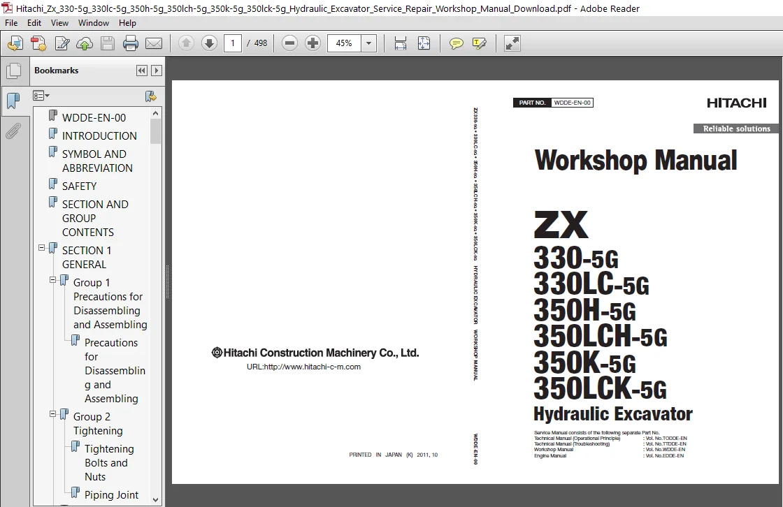
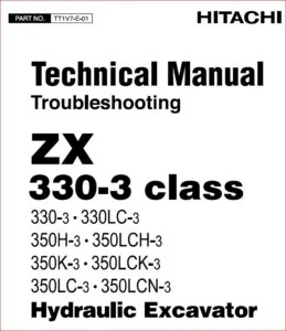
Hitachi Zx 330-5g 330lc-5g 350h-5g 350lch-5g 350k-5g 350lck-5g Hydraulic Excavator Service Manual Download
Original price was: $34.95.$19.95Current price is: $19.95.
Hitachi Zx 330-5g 330lc-5g 350h-5g 350lch-5g 350k-5g 350lck-5g Hydraulic Excavator Service Manual Download
Description
Hitachi Zx 330-5g 330lc-5g 350h-5g 350lch-5g 350k-5g 350lck-5g Hydraulic Excavator Service Manual Download
FILE DETAILS:
Hitachi Zx 330-5g 330lc-5g 350h-5g 350lch-5g 350k-5g 350lck-5g Hydraulic Excavator Service Manual Download
LANGUAGE:ENGLISH
PAGES:498
DOWNLOADABLE:YES
FILE TYPE:PDF
HITACHI ZX 330-5G 330LC-5G 350H-5G 350LCH-5G 350K-5G 350LCK-5G HYDRAULIC EXCAVATOR SERVICE MANUAL DOWNLOAD:
IMAGES PREVIEW OF THE MANUAL:
DESCRIPTION:
Hitachi Zx 330-5g 330lc-5g 350h-5g 350lch-5g 350k-5g 350lck-5g Hydraulic Excavator Service Manual Download
manual consists the Technical Manual, the Workshop Manual and the Engine Manual. Information included in the Technical Manual: Technical information needed for redelivery and delivery, operation and activation of all devices and systems, operational performance tests, and troubleshooting procedures. Information included in the Workshop Manual: Technical information needed for maintenance and repair of the machine, tools and devices needed for maintenance and repair, maintenance standards, and removal / installation and assemble / disassemble procedures. Information included in the Engine Manual: Technical information needed for redelivery and delivery and maintenance and repair of the machine, operation and activation of all devices and systems, troubleshooting and assemble / disassemble procedures.
TABLE OF CONTENTS:
Hitachi Zx 330-5g 330lc-5g 350h-5g 350lch-5g 350k-5g 350lck-5g Hydraulic Excavator Service Manual Download
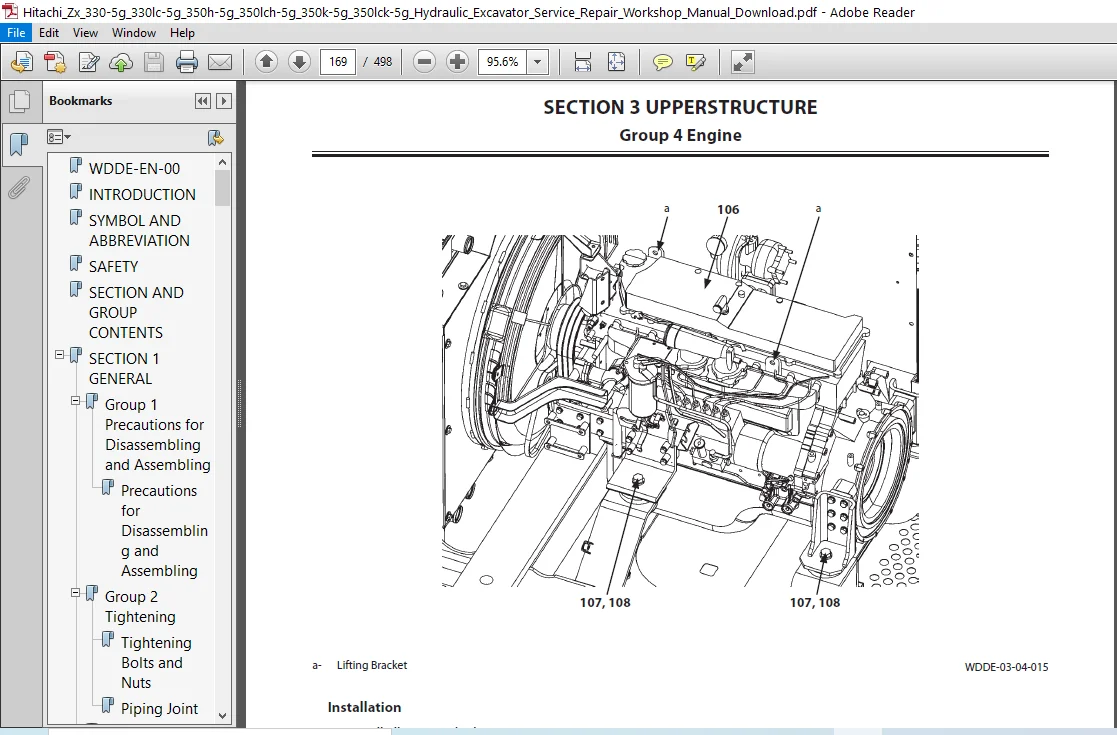
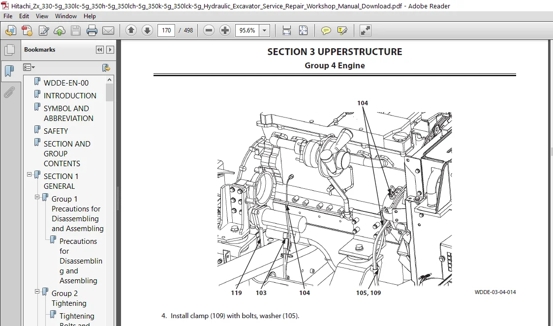
WDDE-EN-00...........................................................  1
INTRODUCTION.........................................................  3
SYMBOL AND ABBREVIATION..............................................  5
SAFETY...............................................................  7
SECTION AND GROUP CONTENTS........................................... 47
SECTION 1 GENERAL.................................................... 49
	Group 1 Precautions for Disassembling and Assembling............. 51
		Precautions for Disassembling and Assembling................. 51
	Group 2 Tightening............................................... 57
		Tightening Bolts and Nuts.................................... 57
		Piping Joint................................................. 60
	Group 3 Painting................................................. 65
		Painting..................................................... 65
	Group 4 Bleeding Air............................................. 67
		Bleeding Air from Hydraulic Oil Tank......................... 67
		Bleeding Air from Hydraulic System........................... 68
		Bleeding Air from Fuel System................................ 69
	Group 5 Pressure Release Procedure............................... 71
		Hydraulic Circuit Pressure Release Procedure................. 71
	Group 6 Preparation.............................................. 73
		Preparation before Inspection and Maintenance................ 73
SECTION 2 MAINTENANCE STANDARD....................................... 77
	Group 1 Upperstructure........................................... 79
		Pump Device.................................................. 79
		Swing Motor.................................................. 83
	Group 2 Undercarriage............................................ 87
		Travel Motor................................................. 87
		Sprocket..................................................... 89
		Front Idler.................................................. 91
		Upper Roller................................................. 93
		Lower Roller................................................. 94
		Track........................................................ 95
	Group 3 Front Attachment......................................... 99
		Pin and Bushing.............................................. 99
		Side Cutter..................................................101
		Point........................................................101
		Side Cutter..................................................102
		Point........................................................102
		Standard Dimensions for Arm and Bucket Connection............103
		Standard Dimensions for Arm and Boom Connection..............104
		Cylinder.....................................................105
SECTION 3 UPPERSTRUCTURE.............................................109
	Group 1 Cab......................................................111
		Removal and Installation of Cab..............................111
		Dimensions of Cab Glass......................................127
	Group 2 Counterweight............................................147
		Removal and Installation of Counterweight....................147
	Group 3 Main Frame...............................................151
		Removal and Installation of Main Frame.......................151
	Group 4 Engine...................................................157
		Removal and Installation of Engine...........................157
	Group 6 Hydraulic Oil Tank.......................................181
		Removal and Installation of Hydraulic Oil Tank...............181
	Group 7 Fuel Tank................................................189
		Removal and Installation of Fuel Tank........................189
	Group 8 Pump Device..............................................197
		Removal and Installation of Pump Device......................197
		Removal and Installation of Coupling.........................207
		Disassembly of Pump Device...................................209
		Assembly of Pump Device......................................212
		Disassembly of Main Pump.....................................217
		Assembly of Main Pump........................................222
		Disassembly of Regulator.....................................231
		Assembly of Regulator........................................233
		Disassembly of Pilot Pump....................................235
		Assembly of Pilot Pump.......................................237
	Group 9 Control Valve............................................239
		Disassembly of Housing.......................................253
		Assembly of Housing..........................................255
		Disassembly of Control Valve (4-Spool Side)..................257
		Assembly of Control Valve (4-Spool Side).....................264
		Disassembly of Control Valve (5-Spool Side)..................275
		Assembly of Control Valve (5-Spool Side).....................282
	Group 10 Swing Device............................................291
		Removal and Installation of Swing Device.....................291
		Disassembly of Swing Device..................................295
		Assembly of Swing Device.....................................301
		Disassembly of Swing Motor...................................307
		Assembly of Swing Motor......................................310
		Structure of Swing Parking Brake Switch Valve................313
	Group 11 Pilot Valve.............................................315
		Removal and Installation of Pilot Valve (Left)...............315
		Removal and Installation of Pilot Valve (Right)..............321
		Removal and Installation of Travel Pilot Valve...............329
		Disassembly of Pilot Valves (Right and Left).................333
		Assembly of Pilot Valves (Right and Left)....................336
		Disassembly of Travel Pilot Valve............................339
		Assembly of Travel Pilot Valve...............................343
	Group 12 Solenoid Valve..........................................349
		Removal and Installation of Pilot Shut-Off Solenoid Valve....349
		Removal and Installation of 3-Spool Solenoid Valve Unit......353
		Disassembly of Pilot Shut-Off Solenoid Valve.................357
		Assembly of Pilot Shut-Off Solenoid Valve....................359
		Structure of 3-Spool Solenoid Valve Unit.....................361
	Group 13 Signal Control Valve....................................363
		Removal and Installation of Signal Control Valve.............363
		Structure of Signal Control Valve............................369
SECTION 4 UNDERCARRIAGE..............................................373
	Group 1 Swing Bearing............................................375
		Removal and Installation of Swing Bearing....................375
		Disassembly of Swing Bearing.................................379
		Assembly of Swing Bearing....................................382
	Group 2 Travel Device............................................385
		Removal and Installation of Travel Device....................385
		Disassembly of Travel Device.................................389
		Assembly of Travel Device....................................393
		Disassembly of Travel Motor..................................401
		Assembly of Travel Motor.....................................404
		Disassembly of Brake Valve...................................409
		Assembly of Brake Valve......................................411
	Group 3 Center Joint.............................................415
		Removal and Installation of Center Joint.....................415
		Disassembly of Center Joint..................................419
		Assembly of Center Joint.....................................421
		Replacement of Body and Spindle..............................424
	Group 4 Track Adjuster...........................................425
		Removal and Installation of Track Adjuster...................425
		Disassembly of Front Idler...................................429
		Assembly of Front Idler......................................432
	Group 5 Upper and Lower Rollers..................................437
		Removal and Installation of Upper Roller.....................437
		Removal and Installation of Lower Roller.....................441
		Disassembly of Lower Roller..................................445
		Assembly of Lower Roller.....................................447
	Group 6 Track....................................................451
		Removal and Installation of Track............................451
SECTION 5 FRONT ATTACHMENT...........................................459
	Group 1 Front Attachment.........................................461
		Removal and Installation of Front Attachment.................461
	Group 2 Cylinder.................................................469
		Removal and Installation of Boom Cylinder....................469
		Removal and Installation of Arm Cylinder.....................473
		Removal and Installation of Bucket Cylinder..................477
		Disassembly of Boom, Arm, and Bucket Cylinders...............481
		Assembly of Boom, Arm, and Bucket Cylinders..................485
		Disassembly of Boom, Arm, and Bucket Cylinders...............489
		Assembly of Boom, Arm, and Bucket Cylinders..................493
PLEASE NOTE:
- This is the SAME exact manual used by your dealers to fix your vehicle.
- The same can be yours in the next 2-3 mins as you will be directed to the download page immediately after paying for the manual.
- Any queries / doubts regarding your purchase, please feel free to contact [email protected]

Derrick Manuel –
Quick and easy , thanks