Hitachi ZX135US-5B Hydraulic Excavator Technical Operational Principle Manual (TODAE-EN-00) – PDF Download
Original price was: $67.95.$24.95Current price is: $24.95.
- Hitachi ZX135US-5B Hydraulic Excavator Technical Operational Principle Manual
- Part No:TODAE-EN-00
Description
Hitachi ZX135US-5B Hydraulic Excavator Technical Operational Principle Manual (TODAE-EN-00)
File Details:
Hitachi ZX135US-5B Hydraulic Excavator Technical Operational Principle Manual (TODAE-EN-00)
- Manual Language:English
- Downloadable:Yes
- Pages: 418
- Size: 13.8 MB
- Format:PDF
HITACHI ZX135US-5B HYDRAULIC EXCAVATOR TECHNICAL OPERATIONAL PRINCIPLE MANUAL (TODAE-EN-00) – PDF DOWNLOAD:
Image Preview:
Description:
Hitachi ZX135US-5B Hydraulic Excavator Technical Operational Principle Manual (TODAE-EN-00)
To The Reader
This manual is written for an experienced technician to provide technical information needed to maintain and repair this machine.
Be sure to thoroughly read this manual for correct product information and service procedures.
If you have any questions or comments, at if you found any errors regarding the contents of this manual, please contact using “Service Manual Revision Request Form” at the end of this manual.
Additional References
Please refer to the other materials (operator’s manual, parts catalog, engine technical material and Hitachi training material etc.) in addition to this manual.
Manual Composition
This manual consists the Technical Manual, the Workshop Manual and the Engine Manual.
Information included in the Technical Manual: Technical information needed for redelivery and delivery, operation and activation of all devices and systems, operational performance tests, and troubleshooting procedures.
Information included in the Workshop Manual: Technical information needed for maintenance and repair of the machine, tools and devices needed for maintenance and repair, maintenance standards, and removal / installation and assemble / disassemble procedures.
Information included in the Engine Manual: Technical information needed for redelivery and delivery and maintenance and repair of the machine, operation and activation of all devices and systems, troubleshooting and assemble / disassemble procedures.
Table Of Contents:
Hitachi ZX135US-5B Hydraulic Excavator Technical Operational Principle Manual (TODAE-EN-00)
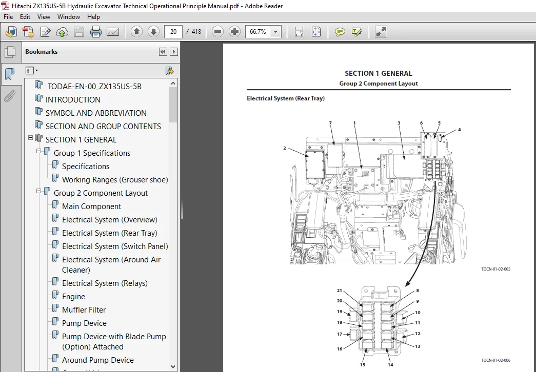
TODAE-EN-00_ZX135US-5B....................................................................................................................................................  1
INTRODUCTION...............................................................................................................................................................  3
SYMBOL AND ABBREVIATION....................................................................................................................................................  5
SECTION AND GROUP CONTENTS.................................................................................................................................................  7
SECTION 1 GENERAL..........................................................................................................................................................  9
	Group 1 Specifications................................................................................................................................................. 11
		Specifications..................................................................................................................................................... 11
		Working Ranges (Grouser shoe)...................................................................................................................................... 13
	Group 2 Component Layout............................................................................................................................................... 15
		Main Component..................................................................................................................................................... 15
		Electrical System (Overview)....................................................................................................................................... 19
		Electrical System (Rear Tray)...................................................................................................................................... 20
		Electrical System (Switch Panel)................................................................................................................................... 21
		Electrical System (Around Air Cleaner)............................................................................................................................. 22
		Electrical System (Relays)......................................................................................................................................... 23
		Engine............................................................................................................................................................. 24
		Muffler Filter..................................................................................................................................................... 25
		Pump Device........................................................................................................................................................ 26
		Pump Device with Blade Pump (Option) Attached...................................................................................................................... 26
		Around Pump Device................................................................................................................................................. 27
		Control Valve...................................................................................................................................................... 28
		Signal Control Valve............................................................................................................................................... 28
		Swing Device....................................................................................................................................................... 30
		Travel Device...................................................................................................................................................... 30
		4-Spool Solenoid Valve Unit........................................................................................................................................ 31
		2-Spool Solenoid Valve Unit (Muffler Filter Regeneration Control).................................................................................................. 31
		Machines with the Blade Attached................................................................................................................................... 32
	Group 3 Component Specifications....................................................................................................................................... 33
		Engine............................................................................................................................................................. 33
		Engine Accessories................................................................................................................................................. 37
		Hydraulic Component................................................................................................................................................ 38
		Electrical Component............................................................................................................................................... 42
		Optional Parts..................................................................................................................................................... 43
SECTION 2 SYSTEM........................................................................................................................................................... 47
	Group 1 Controller..................................................................................................................................................... 49
		Outline............................................................................................................................................................ 49
		CAN Circuit........................................................................................................................................................ 50
	Group 2 Control System................................................................................................................................................. 53
		Outline............................................................................................................................................................ 53
		Engine Control..................................................................................................................................................... 56
		Pump Control....................................................................................................................................................... 88
		Valve Control (Standard)...........................................................................................................................................100
		Valve Control (Option).............................................................................................................................................118
		Other Control......................................................................................................................................................128
	Group 3 ECM System.....................................................................................................................................................139
		Outline............................................................................................................................................................139
		Fuel Injection Control.............................................................................................................................................140
		Fuel Injection Amount Correction Control...........................................................................................................................148
		EGR Control........................................................................................................................................................150
		Preheating Control.................................................................................................................................................152
		Alarm Control......................................................................................................................................................153
		Muffler Filter.....................................................................................................................................................154
		Operation..........................................................................................................................................................155
		Muffler Filter Regenerative Control................................................................................................................................156
	Group 4 Hydraulic System...............................................................................................................................................159
		Outline............................................................................................................................................................159
		Pilot Circuit......................................................................................................................................................160
		Main Circuit.......................................................................................................................................................172
		Outline (2-Piece Boom).............................................................................................................................................191
		Pilot Circuit (2-Piece Boom).......................................................................................................................................192
		Main Circuit (2-Piece Boom)........................................................................................................................................196
	Group 5 Electrical System..............................................................................................................................................201
		Outline............................................................................................................................................................201
		Main Circuit.......................................................................................................................................................202
		Electric Power Circuit (Key Switch: OFF)...........................................................................................................................204
		CAN Circuit........................................................................................................................................................206
		Accessory Circuit..................................................................................................................................................208
		Starting Circuit (Key Switch: START)...............................................................................................................................210
		Charging Circuit (Key Switch: ON)..................................................................................................................................212
		Surge Voltage Prevention Circuit...................................................................................................................................216
		Pilot Shut-Off Circuit (Key switch: ON)............................................................................................................................218
		Auto Shut-Down Circuit/Automatic Engine Stop Circuit at Low Temperature............................................................................................220
		Engine Stop Circuit................................................................................................................................................222
		Monitor Circuit....................................................................................................................................................225
		Security Circuit...................................................................................................................................................226
		Radio Circuit......................................................................................................................................................228
		Air Conditioner Circuit............................................................................................................................................228
		Accessory Circuit..................................................................................................................................................231
		Work Light Circuit.................................................................................................................................................232
		Wiper/Washer Circuit...............................................................................................................................................234
		Cab Light Circuit..................................................................................................................................................236
SECTION 3 COMPONENT OPERATION..............................................................................................................................................241
	Group 1 Pump Device....................................................................................................................................................243
		Outline............................................................................................................................................................243
		Main Pump..........................................................................................................................................................244
		Regulator..........................................................................................................................................................246
		Solenoid Valve.....................................................................................................................................................264
		Pilot Pump, Blade Pump (Optional)..................................................................................................................................266
		Pump Delivery Pressure Sensor......................................................................................................................................266
		Pump Control Pressure Sensor.......................................................................................................................................266
	Group 2 Swing Device...................................................................................................................................................267
		Outline............................................................................................................................................................267
		Swing Reduction Gear...............................................................................................................................................268
		Swing Motor........................................................................................................................................................269
		Swing Parking Brake................................................................................................................................................270
		Valve Unit.........................................................................................................................................................272
	Group 3 Control Valve..................................................................................................................................................275
		Outline............................................................................................................................................................275
		Hydraulic Circuit..................................................................................................................................................294
		Flow Combiner Valve................................................................................................................................................300
		Main Relief Valve..................................................................................................................................................302
		Overload Relief Valve (with Make-Up Function)......................................................................................................................306
		Regenerative Valve.................................................................................................................................................310
		Anti-Drift Valve...................................................................................................................................................318
		Flow Rate Control Valve............................................................................................................................................322
		Digging Regenerative Valve.........................................................................................................................................326
		Boom Lower Meter-In Cut Valve......................................................................................................................................328
		Auxiliary Flow Combiner Valve and Bypass Shut-Out Valve............................................................................................................330
		Blade Control Valve (Optional), Positioning Control Valve (Optional)...............................................................................................334
		2-Piece Boom (Optional)............................................................................................................................................336
		Blade Circuit (Optional)...........................................................................................................................................340
	Group 4 Pilot Valve....................................................................................................................................................343
		Outline............................................................................................................................................................343
		Operation (Front Attachment / Swing and Travel Pilot Valves).......................................................................................................345
		Operation (Auxiliary / Blade / Positioning Pilot Valve)............................................................................................................353
		Shockless Function (Only for Travel Pilot Valve)...................................................................................................................358
	Group 5 Travel Device..................................................................................................................................................359
		Outline............................................................................................................................................................359
		Travel Reduction Gear..............................................................................................................................................360
		Travel Motor.......................................................................................................................................................362
		Parking Brake......................................................................................................................................................364
		Travel Brake Valve.................................................................................................................................................366
		Overload Relief Valve..............................................................................................................................................370
		Travel Mode Control................................................................................................................................................372
	Group 6 Signal Control Valve...........................................................................................................................................377
		Outline............................................................................................................................................................377
		Pilot Port.........................................................................................................................................................378
		Shuttle Valve......................................................................................................................................................383
		Shockless Valve....................................................................................................................................................386
		Pump 1 and 2 Flow Rate Control Valve...............................................................................................................................390
		Bucket Flow Rate Control Valve Control Spool, Flow Combiner Valve Control Spool, Swing Parking Brake Release Spool, Arm 1 Flow Rate Control Valve Control Spool....392
	Group 7 Others (Upperstructure)........................................................................................................................................395
		Pilot Shut-Off Solenoid Valve......................................................................................................................................395
		Solenoid Valve.....................................................................................................................................................397
		Hose Rupture Valve.................................................................................................................................................402
		Pilot Relief Valve.................................................................................................................................................408
		Recirculation Valve (Option).......................................................................................................................................409
	Group 8 Others (Undercarriage).........................................................................................................................................411
		Swing Bearing......................................................................................................................................................411
		Center Joint.......................................................................................................................................................412
		Track Adjuster.....................................................................................................................................................414
SERVICE MANUAL REVISION REQUEST FORM.......................................................................................................................................417
Please Note:
⦁ This is the same manual used by the DEALERSHIPS to SERVICE your vehicle.
⦁ The manual can be all yours – Once payment is complete, you will be taken to the download page from where you can download the manual. All in 2-5 minutes time!!
⦁ Need any other service / repair / parts manual, please feel free to contact us at heydownloadss @gmail.com . We may surprise you with a nice offer
Lucas –
Good and secure way for shopping.