
Hitachi ZX170W-3 ZX190W-3 Wheeled Hydraulic Excavator Workshop Manual PDF
Original price was: $39.95.$23.95Current price is: $23.95.
Complete Hitachi ZX170W-3 and ZX190W-3 wheeled hydraulic excavator Workshop Manual in PDF. Covers disassembly, assembly, tightening torques, component overhaul, and full teardown/rebuild procedures for every major machine group.
Description
Hitachi ZX170W-3 ZX190W-3 Workshop Manual – PDF
This is the Hitachi ZX170W-3 / ZX190W-3 Workshop Manual – the heavy-repair volume of the Hitachi service documentation set for the ZX170W-3 and ZX190W-3 wheeled hydraulic excavators. It is the section a technician reaches for when a component has to come off the machine, be stripped on the bench, measured, resealed, reassembled, and reinstalled to specification. Everything in this PDF is written for the experienced technician working on these exact two wheeled excavator models.
The manual opens with general information covering disassembly and assembly precautions, tightening torque specifications, painting, and bleeding air from the hydraulic oil tank, then moves into the three major machine sections: Upperstructure, Undercarriage, and Front Attachment. Within each section, every group is broken into removal and installation, disassembly, assembly, structure illustrations, and – where applicable – maintenance standards and allowable limits.
File Details
- Manual type: Workshop Manual (heavy repair / overhaul volume of the Hitachi service documentation set)
- Brand: Hitachi Construction Machinery
- Models covered: ZX170W-3, ZX190W-3 (wheeled hydraulic excavators)
- Language: English
- Format: PDF
- Approximate page count: 604 pages
- Section coverage: Section 1 General Information, Section 2 Upperstructure, Section 3 Undercarriage, Section 4 Front Attachment
- Units used: SI units, with MKSA and English equivalents shown in parentheses
Chapters and Groups Covered
Section 1 – General Information
- Precautions for Disassembling and Assembling (including floating seal handling and nylon sling usage)
- Maintenance Standard Terminology (Standard / Allowable Limit)
- Tightening – torque specifications, torque chart, piping joints (ORS, metal face seal, screw-in connections), seal tape application, low-pressure hose clamp tightening
- Periodic Replacement of Parts schedule
- Painting – specification and final painted colours
- Bleeding Air from Hydraulic Oil Tank – preparation and procedure
Section 2 – Upperstructure
- Cab – removal and installation, dimensions of cab glass (removal and installation of right-hand glass, rear glass, rear left-hand glass, lower door glass, upper front glass)
- Counterweight – removal and installation
- Main Frame – removal and installation
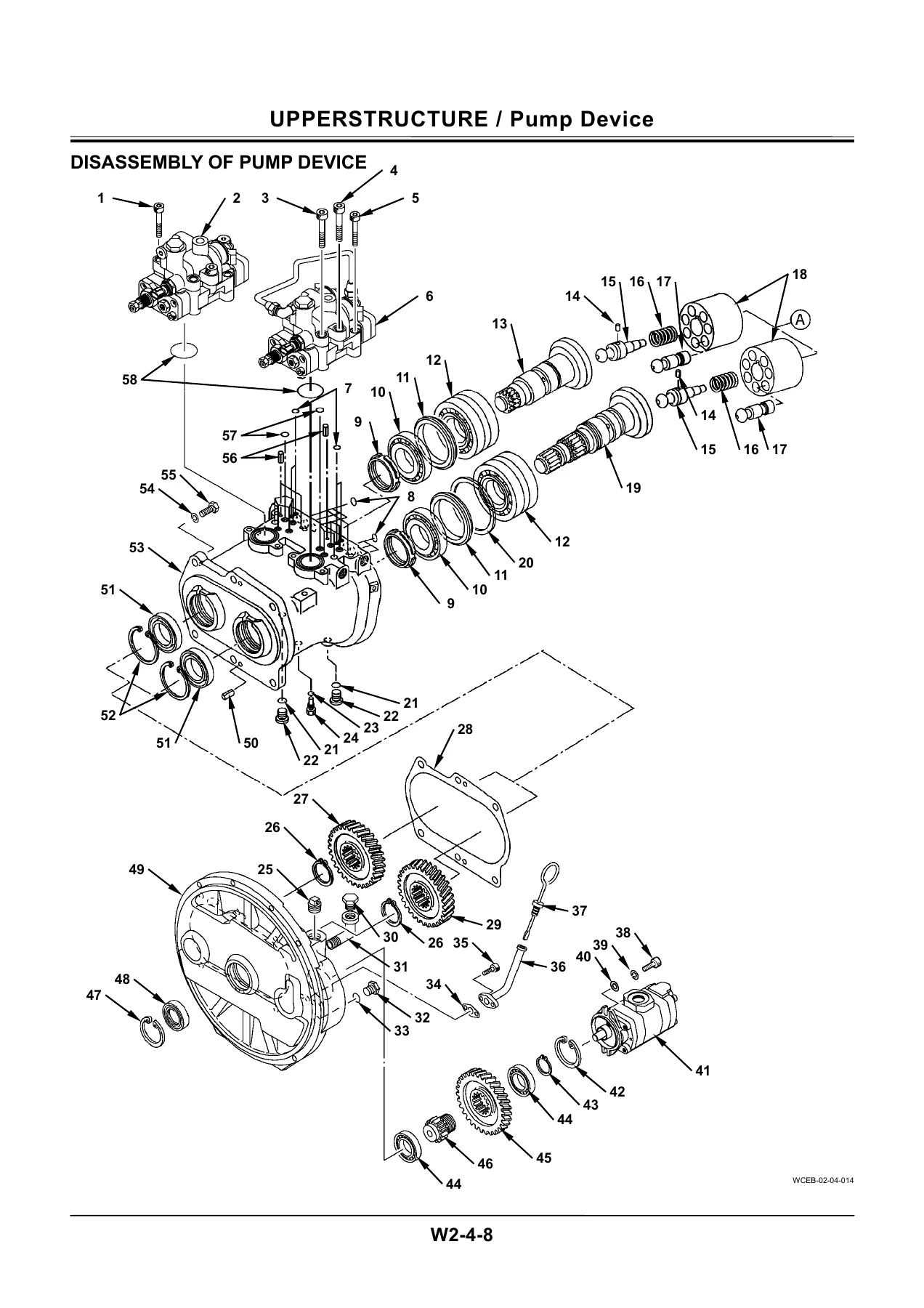
- Pump Device – removal and installation, disassembly, assembly, regulator disassembly and assembly, pilot pump structure
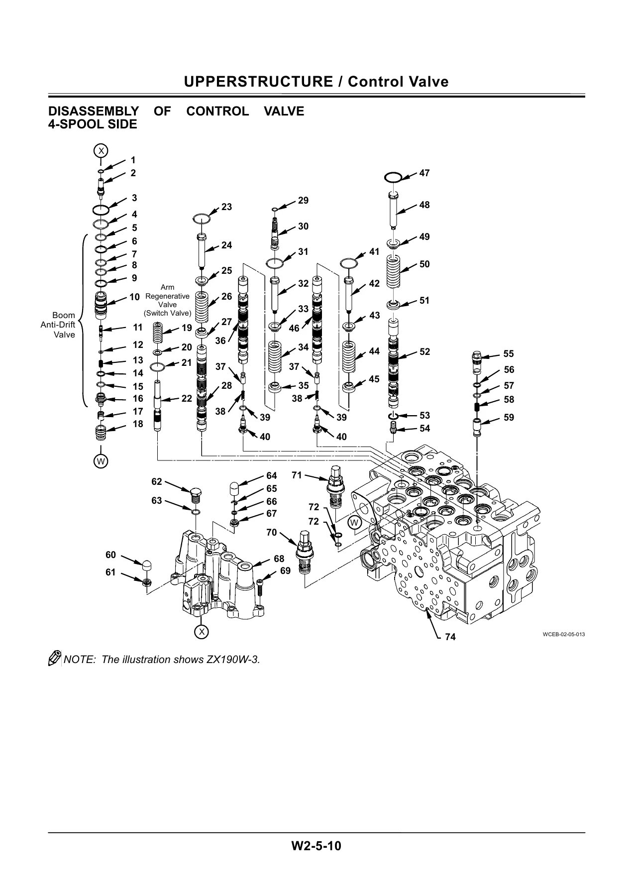
- Control Valve – removal and installation, 4-spool side disassembly, 5-spool side disassembly, assembly of both sides, positioning control valve removal/installation, disassembly, assembly
- Swing Device – removal and installation, disassembly, assembly, swing motor disassembly and assembly, swing dampener valve structure, maintenance standard
- Pilot Valve – removal and installation, front/swing pilot valve disassembly and assembly, travel pilot valve removal and installation, travel and auxiliary/positioning pilot valve disassembly and assembly
- Electric Lever – removal and installation, disassembly and assembly
- Signal Control Valve – removal and installation, structure
- Shockless Valve – removal and installation, swing shockless valve structure, travel shockless valve structure
- Solenoid Valve – 3-spool solenoid valve unit removal/installation, structure, disassembly and assembly, electric lever solenoid valve unit
- Pilot Shut-Off Solenoid Valve – removal and installation, structure
- Steering Valve – removal and installation
- Brake Valve – removal and installation, disassembly and assembly
- Accumulator Charge Valve – removal and installation, structure
Section 3 – Undercarriage
- Swing Bearing – removal and installation, disassembly and assembly
- Travel Motor – removal and installation, disassembly and assembly, brake valve disassembly and assembly
- Center Joint – removal and installation, disassembly and assembly
- Transmission – removal and installation, disassembly and assembly
- Axle – front axle removal/installation and disassembly/assembly, rear axle removal/installation and disassembly/assembly, differential disassembly and assembly, steering cylinder disassembly and assembly
- Axle Lock Cylinder – removal and installation, disassembly and assembly
- Operate Check Valve – removal and installation, structure
- Solenoid Valve – outrigger/blade solenoid valve unit removal and installation, structure
- Transmission Changeover Solenoid Valve – removal and installation
- Propeller Shaft – removal and installation
Section 4 – Front Attachment
- Front Attachment – hydraulic circuit pressure release procedure, removal and installation (monoblock boom), removal and installation (2-piece boom), maintenance standard, standard dimensions for arm and bucket connection, standard dimensions for arm and boom connection
- Cylinder – pressure release procedure, removal and installation, boom/arm/bucket cylinder disassembly and assembly, positioning cylinder disassembly and assembly, outrigger and blade cylinder disassembly and assembly, maintenance standard
- Hose Rupture Valve – pressure release procedure, removal and installation for arm cylinder, positioning cylinder, and boom cylinder, structure of each
- Operate Check Valve – removal and installation for blade and outrigger, structure
What This Manual Gives a Technician
This ZX170W-3 / ZX190W-3 Workshop Manual is a bench-and-floor document. Every major assembly on the wheeled excavator is presented in the sequence a mechanic actually works: how it comes off the machine, how it comes apart on the bench, which special tool is used at each step, which measurements go into the inspection record, and how it goes back together with the correct torque and alignment marks.
Component weights are called out before lifting points are introduced, so the lifting sling and hoist capacity can be checked in advance. Matching marks and identification tags are specified for spool assemblies, plungers, rotors, and hydraulic fittings so that parts are not swapped between positions. Hydraulic circuit pressure-release procedures for the front attachment, cylinder, and hose rupture valve groups are given in the same format, ensuring that residual pressure is removed before a single line is cracked.
The structure drawings and exploded views in each group are labelled with the numbered component list printed on the facing page, so a rebuild does not depend on guessing the order of shims, rings, seal stacks, or spring seats.
Tightening and Torque Data
A dedicated tightening chapter lists fastener sizes with torque values for the ZX190W-3 machine, including engine cushion rubber mounting bolts, pump mounting bolts, control valve mounting bolts, swing device mounting bolts, swing bearing mounting bolts to both uppertructure and chassis, center joint lock mounting bolts, travel motor mounting bolts, rear axle mounting bolts, wheel pin nuts, and cover mounting bolts. Also included are the split-flange, ORS, and screw-in hydraulic fitting tightening data, seal tape application procedure, and low-pressure hose clamp torque values for both T-bolt and worm gear band clamps.
Component and Assembly Weights Referenced
- Cab – 550 kg (1220 lb)
- Counterweight – ZX170W-3: 3600 kg (7940 lb); ZX190W-3: 4200 kg (9260 lb)
- Uppertructure – 4800 kg (10600 lb)
- Front attachment – ZX170W-3 monoblock boom 2580 kg (5690 lb), 2-piece boom 3180 kg (7020 lb); ZX190W-3 monoblock boom 2990 kg (6600 lb), 2-piece boom 3570 kg (7870 lb)
- Pump device – 195 kg (430 lb)
- Control valve – 155 kg (300 lb)
- Swing device – 225 kg (500 lb)
- Travel motor – 80 kg (180 lb)
- Center joint – 90 kg (200 lb)
- Front axle – 650 kg (1440 lb); rear axle – 600 kg (1330 lb)
These figures are printed alongside the removal procedures so the correct lifting equipment is in place before the machine is opened up.
Who This Workshop Manual Is For
Independent repair shops, dealer-trained technicians, fleet maintenance departments, and owners who intend to carry out their own major repairs on the ZX170W-3 or ZX190W-3. The procedures assume access to a proper workshop, a hydraulic press, lifting equipment, and the specified special tools – which the manual identifies by tool number where used.
Take the Repair Into Your Own Hands
With the Hitachi ZX170W-3 ZX190W-3 Wheeled Hydraulic Excavator Workshop Manual PDF on the bench, a full teardown of the pump device, control valve, swing device, travel motor, transmission, axles, or the front attachment cylinders is a documented job – not an exercise in guesswork. Torque values, seal directions, matching marks, and measurement standards are all present in the same volume, so nothing has to be cross-referenced between documents while a machine is apart.
IMAGES PREVIEW
Delivered as an instant PDF download after checkout – no shipping, no waiting, no physical binder. Read it on a laptop, tablet, or phone in the workshop, or print the pages you need for the job in hand and keep them beside the machine. The ZX170W-3 and ZX190W-3 Workshop Manual is the reference a serious repair begins with.

Reviews
There are no reviews yet.