Hitachi ZX300-5A ZX300LC-5A ZX300LCH-5A Hydraulic Excavator Workshop Manual (WDDW90-EN-00) – PDF Download
Original price was: $89.95.$26.95Current price is: $26.95.
- Hitachi ZX300-5A ZX300LC-5A ZX300LCH-5A Hydraulic Excavator Workshop Manual
- Part No:WDDW90-EN-00
Description
Hitachi ZX300-5A ZX300LC-5A ZX300LCH-5A Hydraulic Excavator Workshop Manual (WDDW90-EN-00)
File Details:
Hitachi ZX300-5A ZX300LC-5A ZX300LCH-5A Hydraulic Excavator Workshop Manual (WDDW90-EN-00)
- Manual Language:English
- Pages: 1100+
- Size: 15.0 MB
- Format:PDF
- Downloadable:Yes
HITACHI ZX300-5A ZX300LC-5A ZX300LCH-5A HYDRAULIC EXCAVATOR WORKSHOP MANUAL (WDDW90-EN-00) – PDF DOWNLOAD:
Image Preview:
Description:
Hitachi ZX300-5A ZX300LC-5A ZX300LCH-5A Hydraulic Excavator Workshop Manual (WDDW90-EN-00)
To The Reader
This manual is written for an experienced technician to provide technical information needed to maintain and repair this machine. The machine specification and description according to destination may be explained on this manual.
Be sure to thoroughly read this manual for correct product information and service procedures.
If you have any questions or comments, at if you found any errors regarding the contents of this manual, please contact using “Service Manual Revision Request Form” at the end of this manual.
Additional References
Please refer to the other materials (operator’s manual, parts catalog, engine technical material and Hitachi training material etc.) in addition to this manual.
Manual Composition
This manual consists the Technical Manual, the Workshop Manual and the Engine Manual.
Information included in the Technical Manual: Technical information needed for redelivery and delivery, operation and activation of all devices and systems, operational performance tests, and troubleshooting procedures.
Information included in the Workshop Manual: Technical information needed for maintenance and repair of the machine, tools and devices needed for maintenance and repair, maintenance standards, and removal / installation and assemble / disassemble procedures.
Information included in the Engine Manual: Technical information needed for redelivery and delivery and maintenance and repair of the machine, operation and activation of all devices and systems, troubleshooting and assemble / disassemble procedures.
Table Of Contents:
Hitachi ZX300-5A ZX300LC-5A ZX300LCH-5A Hydraulic Excavator Workshop Manual (WDDW90-EN-00)
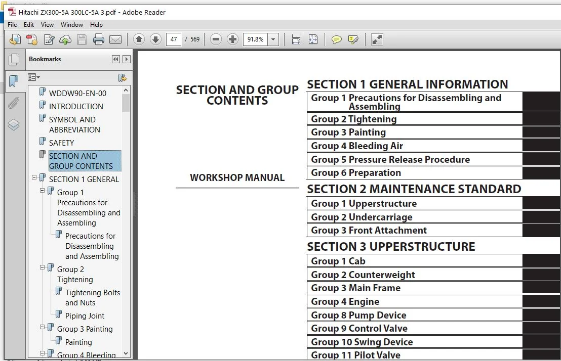
WDDW90-EN-00..............................................................  1
INTRODUCTION..............................................................  3
SYMBOL AND ABBREVIATION...................................................  5
SAFETY....................................................................  7
SECTION AND GROUP CONTENTS................................................ 47
SECTION 1
GENERAL......................................................... 49
	Group 1 Precautions for Disassembling and Assembling.................. 51
		Precautions for Disassembling and Assembling...................... 51
	Group 2 Tightening.................................................... 57
		Tightening Bolts and Nuts......................................... 57
		Piping Joint...................................................... 60
	Group 3 Painting...................................................... 67
		Painting.......................................................... 67
	Group 4 Bleeding Air.................................................. 69
		Bleeding Air from Hydraulic Oil Tank (Pressure Release)........... 69
		Bleeding Air from Hydraulic System................................ 70
		Bleeding Air from Fuel System..................................... 71
		Bleeding Air from Expansion Tank (Radiator) (Pressure Release).... 73
	Group 5 Pressure Release Procedure.................................... 75
		Hydraulic Circuit Pressure Release Procedure...................... 75
	Group 6 Preparation................................................... 77
		Preparation before Inspection and Maintenance..................... 77
SECTION 2
MAINTENANCE STANDARD............................................ 81
	Group 1 Upperstructure................................................ 83
		Pump Device....................................................... 83
		Swing Motor....................................................... 87
	Group 2 Undercarriage................................................. 91
		Travel Motor...................................................... 91
		Sprocket.......................................................... 93
		Front Idler....................................................... 95
		Upper Roller...................................................... 97
		Lower Roller...................................................... 98
		Track............................................................. 99
	Group 3 Front Attachment..............................................103
		Pin and Bushing...................................................103
		Side Cutter (2021232, 2021233)....................................105
		Point (4512365)...................................................106
		Standard Dimensions for Arm and Bucket Connection.................107
		Standard Dimensions for Arm and Boom Connection...................108
		Cylinder..........................................................109
SECTION 3
UPPERSTRUCTURE..................................................113
	Group 1 Cab...........................................................115
		Removal and Installation of Cab...................................115
		Dimensions of Cab Glass...........................................143
	Group 2 Counterweight.................................................163
	Group 3 Main Frame....................................................165
		Removal and Installation of Main Frame............................165
	Group 4 Engine........................................................173
		Removal and Installation of Engine................................173
	Group 8 Pump Device...................................................211
		Removal and Installation of Pump Device...........................211
		Removal and Installation of Coupling..............................225
		Disassembly of Pump Device........................................227
		Assembly of Pump Device...........................................230
		Disassembly of Main Pump..........................................235
		Assembly of Main Pump.............................................240
		Disassembly of Regulator..........................................249
		Assembly of Regulator.............................................251
		Disassembly of Pilot Pump.........................................253
		Assembly of Pilot Pump............................................255
	Group 9 Control Valve.................................................257
		Removal and Installation of Control Valve.........................257
		Disassembly of Housing............................................281
		Assembly of Housing...............................................283
		Disassembly of Control Valve (4-Spool Side).......................285
		Assembly of Control Valve (4-Spool Side)..........................292
		Disassembly of Control Valve (5-Spool Side).......................303
		Assembly of Control Valve (5-Spool Side)..........................310
	Group 10 Swing Device.................................................319
		Removal and Installation of Swing Device..........................319
		Disassembly of Swing Device.......................................323
		Assembly of Swing Device..........................................328
		Disassembly of Swing Motor........................................335
		Assembly of Swing Motor...........................................338
		Structure of Swing Parking Brake Switch Valve.....................341
	Group 11 Pilot Valve..................................................343
		Removal and Installation of Pilot Valve (Left)....................343
		Removal and Installation of Pilot Valve (Right)...................355
		Removal and Installation of Travel Pilot Valve....................371
		Disassembly of Pilot Valves (Right and Left)......................375
		Assembly of Pilot Valves (Right and Left).........................378
		Disassembly of Travel Pilot Valve.................................381
		Assembly of Travel Pilot Valve....................................385
	Group 12 Solenoid Valve...............................................391
		Removal and Installation of Pilot Shut-Off Solenoid Valve.........391
		Removal and Installation of 3-Spool Solenoid Valve Unit...........395
		Removal and Installation of 2-Spool Solenoid Valve Unit...........401
		Disassembly of Pilot Shut-Off Solenoid Valve......................407
		Assembly of Pilot Shut-Off Solenoid Valve.........................409
		Structure of 3-Spool Solenoid Valve Unit..........................411
		Structure of 2-Spool Solenoid Valve Unit..........................413
	Group 13 Signal Control Valve.........................................415
		Removal and Installation of Signal Control Valve..................415
		Structure of Signal Control Valve.................................419
SECTION 4
UNDERCARRIAGE...................................................425
	Group 1 Swing Bearing.................................................427
		Removal and Installation of Swing Bearing.........................427
		Disassembly of Swing Bearing......................................433
		Assembly of Swing Bearing.........................................436
	Group 2 Travel Device.................................................439
		Removal and Installation of Travel Device.........................439
		Disassembly of Travel Device......................................443
		Assembly of Travel Device.........................................447
		Disassembly of Travel Motor.......................................455
		Assembly of Travel Motor..........................................458
		Disassembly of Brake Valve........................................463
		Assembly of Brake Valve...........................................465
		Precautions for Using Floating Seal...............................467
	Group 3 Center Joint..................................................469
		Removal and Installation of Center Joint..........................469
		Disassembly of Center Joint.......................................473
		Assembly of Center Joint..........................................475
		Replacement of Body and Spindle...................................478
	Group 4 Track Adjuster................................................479
		Removal and Installation of Track Adjuster........................479
		Disassembly of Front Idler........................................483
		Assembly of Front Idler...........................................486
		Disassembly of Track Adjuster.....................................489
		Assembly of Track Adjuster........................................493
		Precautions for Using Floating Seal...............................497
	Group 5 Upper and Lower Rollers.......................................499
		Removal and Installation of Upper Roller..........................499
		Removal and Installation of Lower Roller..........................503
		Disassembly of Lower Roller.......................................509
		Assembly of Lower Roller..........................................511
		Precautions for Using Floating Seal...............................513
	Group 6 Track.........................................................515
		Removal and Installation of Track.................................515
SECTION 5
FRONT ATTACHMENT................................................525
	Group 1 Front Attachment..............................................527
		Removal and Installation of Front Attachment......................527
	Group 2 Cylinder......................................................535
		Removal and Installation of Boom Cylinder.........................535
		Removal and Installation of Arm Cylinder..........................539
		Removal and Installation of Bucket Cylinder.......................547
		Disassembly of Boom, Arm, and Bucket Cylinders....................551
		Assembly of Boom, Arm, and Bucket Cylinders.......................558
SERVICE MANUAL REVISION REQUEST FORM......................................569
Please Note:
⦁ This is the same manual used by the dealers to diagnose and troubleshoot your vehicle
⦁ You will be directed to the download page as soon as the purchase is completed. The whole payment and downloading process will take anywhere between 2-5 minutes
⦁ Need any other service / repair / parts manual, please feel free to contact [email protected] . We still have 50,000 manuals unlisted


Alessandro Alvaro –