
Hitachi ZX330-5G ZX350-5G Series Hydraulic Excavator Troubleshooting Manual – TTDDE-EN-01
Original price was: $39.95.$24.95Current price is: $24.95.
The Hitachi ZX330-5G / ZX350-5G Series Troubleshooting Manual (TTDDE-EN-01) – fault code diagnosis, operational performance test standards, monitor and e-Service data, component layouts and air conditioner troubleshooting for ZX330-5G, ZX330LC-5G, ZX350H-5G, ZX350LCH-5G, ZX350K-5G and ZX350LCK-5G excavators.
Description
Hitachi ZX330-5G ZX350-5G Series Hydraulic Excavator Troubleshooting Manual
This Hitachi ZX330-5G ZX350-5G Series Hydraulic Excavator Troubleshooting Manual is the troubleshooting volume of the Hitachi Technical Manual set, published under document number TTDDE-EN-01. Where the Operational Principle volume explains how the machine is designed to behave, this manual is built around what to do when it does not behave that way: measuring real performance against published standard values, pulling fault codes out of the controllers, and walking a complaint from a symptom through to the failed part.
It is written for an experienced technician working on the ZX330-5G, ZX330LC-5G, ZX350H-5G, ZX350LCH-5G, ZX350K-5G and ZX350LCK-5G hydraulic excavators, and it assumes you already know how to run the machine and take a pressure reading. What it supplies is the reference data and the decision path.
File Details
- Manual type: Technical Manual (Troubleshooting)
- Document number: TTDDE-EN-01
- Brand: Hitachi
- Models covered: ZX330-5G, ZX330LC-5G, ZX350H-5G, ZX350LCH-5G, ZX350K-5G, ZX350LCK-5G
- Language: English
- Page count: 444
- File format: PDF
Chapters Covered
The troubleshooting volume is organised into two large sections, each divided into numbered groups that carry their own page numbering (for example T4-2-7 or T5-5-19) so a printed page reference stays valid on screen.
- Section 4 – Operational Performance Test
- Group 1: Introduction – purpose of performance tests, kinds of tests, performance standards, test area and precautions
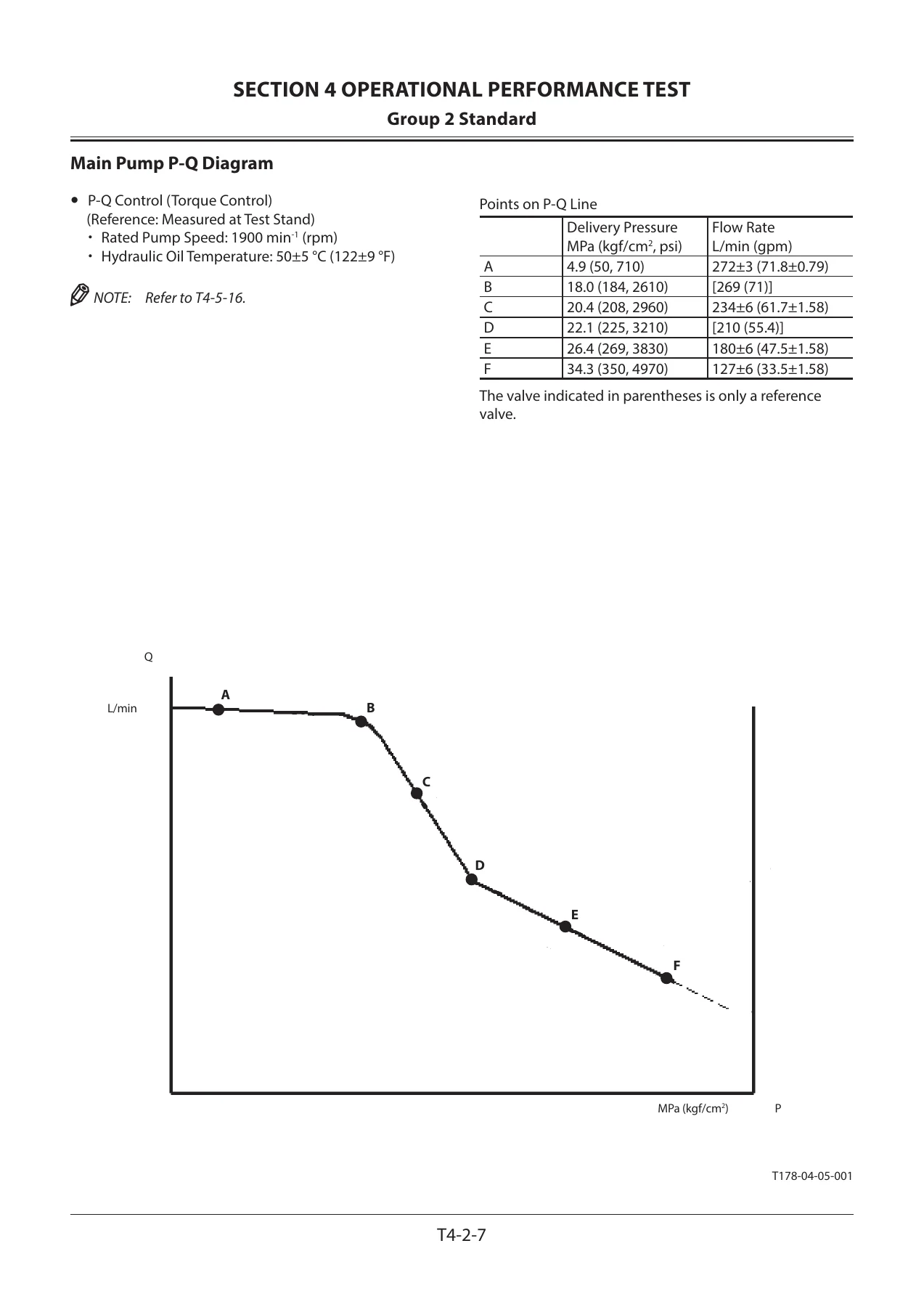
- Group 2: Standard – operational performance standard table, main pump P-Q diagram, sensor activating range, MPDr monitor indicating values
- Group 3: Engine Test – engine speed, engine compression pressure, valve clearance, nozzle, injection timing, lubricant consumption
- Group 4: Machine Performance Test – travel speed, track revolution speed, mistrack check, travel parking leakage, swing speed, swing drift, swing motor leakage, maximum swingable slant angle, swing bearing play, hydraulic cylinder cycle time, dig function drift, control lever operating force, control lever stroke, combined operation checks
- Group 5: Component Test – primary and secondary pilot pressure, solenoid valve set pressure, main pump delivery pressure, main relief set pressure, swing relief pressure, overload relief valve set pressure, main pump flow rate measurement, swing motor drainage, travel motor drainage
- Group 6: Adjustment – engine speed adjustment and engine learning, governor lever and fuel cut lever position
- Section 5 – Troubleshooting
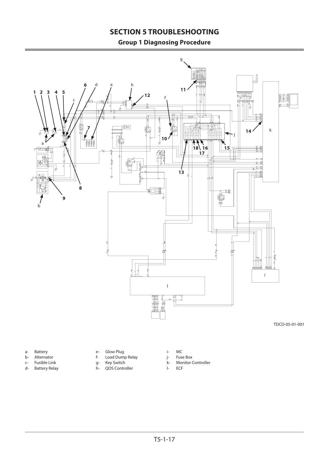
- Group 1: Diagnosing Procedure – electric system inspection, connector handling, fuse and fusible link inspection, battery and alternator checks, continuity checks, voltage and current measurement, false signal checks, test harnesses
- Group 2: Monitor – service menu operation, troubleshooting display, monitoring display, controller version, issued warning record, machine setting, monitor setting, hour meter and fuel gauge inspection
- Group 3: e-Service – operation data, frequency distribution data, total operating hours, snapshot data, communication system
- Group 4: Component Layout – main component, electrical system views, engine, pump device, control valve, signal control valve, swing device, travel device, 3-spool solenoid valve unit, attachment specification parts, components inside the control valve, pilot ports
- Group 5: Troubleshooting A – base machine diagnosis by fault code, including MC, ECF, monitor, air conditioner and communication terminal fault code lists and individual code procedures
- Group 6: Troubleshooting B – base machine diagnosis by symptom, covering engine, all-actuator, front attachment, swing and travel systems plus emergency boom lowering
- Group 7: Air Conditioner – system outline, functions of main parts, fault codes, component replacement work, compressor oil, refrigerant charging, hose and pipe tightening torque
Two distinct diagnostic routes run through this manual, and keeping them straight is what makes it fast to use. Troubleshooting A is entered whenever a fault code is displayed – the controller has already flagged the suspect circuit, so the tables point straight at a connector, a sensor or a harness segment, with the expected voltage or resistance beside the check. Troubleshooting B is entered when no fault code appears but the machine is still wrong. Those procedures work outward from the complaint itself: the front matter maps each symptom against the parts that could produce it, marking which components are genuinely worth checking and which would announce themselves through some other, louder symptom first. In practice you move between the two groups constantly, because a sensor reading slightly out of range can produce a complaint with no code attached.
The performance test section is what separates a diagnosis from a guess. Every measurement – engine speed at slow idle, fast idle, auto-idle and warming-up; travel speed over a measured 10 m; track revolution timing; swing speed over three revolutions; swing drift, dig function drift, cylinder cycle times, control lever stroke and operating force – is given a standard value with a tolerance, plus the switch positions, oil temperature and machine attitude required for the reading to mean anything. Without those preconditions the numbers are worthless, and the manual says so repeatedly.
Hydraulic component testing is covered at the same level of detail. Pilot pressure, main pump delivery pressure, main relief set pressure at both the high-pressure and low-pressure sides, swing relief pressure, overload relief pressure, and pump flow rate against the published P-Q curve all have their own procedures, tool part numbers and adjustment instructions. The pump regulator section goes as far as the individual adjusting screws for minimum flow rate, maximum flow rate, pilot pressure characteristics and P-Q torque control, with the pressure change per quarter turn of each screw listed.
What This Troubleshooting Manual Gives You
Fault codes are listed in full for the main controller, the engine controller, the monitor controller, the air conditioner controller and the communication terminal, including the conditions that trigger each code, the symptoms the operator will actually notice, and the remedy path. Many codes are shown with the high-input and low-input variants side by side, so a shorted harness and an open circuit are never confused for one another.
Wiring and hydraulic reference material is unusually complete for a troubleshooting volume. CAN0 and CAN1 harness checks are laid out pin by pin between the main controller, engine controller, monitor controller, wiper/light controller, radio and air conditioner controller, with continuity and short-circuit checks against ground, power and key-signal circuits. Component layout drawings cover the electrical system in the cab, at the rear tray, at the switch panel, around the air cleaner and at the relay block, plus the control valve spool sections and the pilot port tables that identify every port by letter, name and connection.
Monitor and e-Service coverage explains what the machine can tell you about itself before you open a panel. The service menu gives fault codes, a reduced monitoring set, controller versions, a record of the last ten alarms with timestamps, cumulative hour meters split by operating mode, communication terminal status, and machine settings for slow idle, auto-idle, warming-up and power mode speeds. The e-Service group documents what data the monitor controller records – daily reports, frequency distributions for pump load, coolant temperature and hydraulic oil temperature, and snapshot data captured at the moment a fault occurred.
Coverage Across the -5G Excavator Range
All six variants share this manual. The ZX330-5G and ZX330LC-5G, the ZX350H-5G and ZX350LCH-5G, and the ZX350K-5G and ZX350LCK-5G differ in undercarriage and specification but use the same control architecture, so fault codes, monitor menus and diagnostic procedures apply across the series. Where a value differs between the standard and long-crawler machines – track revolution speed is one example – the alternative figure is printed in the same table row rather than buried in a footnote.
The air conditioner group stands on its own at the back of the manual, covering the refrigerant circuit layout, the function of each sensor and damper servo motor, fault codes 11 through 92, the component replacement sequence, compressor oil quantities by replaced part, the full vacuum and charging procedure with manifold gauge connections, and the tightening torques for the hose and pipe joints.
Who This Manual Is For
This is a diagnostic reference for technicians and workshops servicing the ZX330-5G and ZX350-5G series, and for owners of these machines who want the manufacturer’s own test values rather than a generic hydraulic troubleshooting guide. It assumes access to MPDr, the service menu of the machine monitor, a hydraulic tester and the standard test harnesses listed in Section 5 Group 1 – but the procedures state plainly which tools are required for each test, and many checks can be carried out with a circuit tester and a pressure gauge alone.
IMAGES PREVIEW
Instant PDF Delivery
Your copy of the Hitachi ZX330-5G ZX350-5G Series hydraulic excavator troubleshooting manual arrives as an instant download immediately after payment. There is no shipping, no waiting for a parcel and no risk of a damaged binding. The file opens on a workshop PC, a laptop, a tablet or a phone, pages can be printed for the machine or the bench, and the numbered group page references make it straightforward to print only the section you are working from. One purchase covers all six models in the series.

Reviews
There are no reviews yet.