
Hitachi ZX38U-5A Hydraulic Excavator Workshop Manual WADC-EN-00 2013
Original price was: $39.95.$24.95Current price is: $24.95.
Hitachi ZX38U-5A Hydraulic Excavator Workshop Manual WADC-EN-00, dated 2013 — 366 pages of removal and installation, disassembly and assembly procedures, maintenance standards and tightening data for the ZX38U-5A compact excavator.
Description
Hitachi ZX38U-5A Hydraulic Excavator Workshop Manual (WADC-EN-00, 2013)
Issued under document number WADC-EN-00 and dated 2013, this Hitachi ZX38U-5A Hydraulic Excavator Workshop Manual is the bench-side volume for the technician who has to take the machine apart and put it back together correctly. It carries the removal and installation, disassembly and assembly procedures for the major assemblies, the maintenance standards those assemblies have to meet, the tightening and sealing practice that keeps them leak-free, and the special tools needed to carry each job out. Every procedure is built around the ZX38U-5A compact excavator rather than a general class of machine, so the clearances, wear limits and torque values belong to the machine in front of you.
File Details
- Manual type: Workshop Manual — removal and installation, disassembly and assembly
- Brand: Hitachi
- Machine: ZX38U-5A Hydraulic Excavator
- Document number: WADC-EN-00
- Date: 2013
- Language: English
- Format: PDF
- Extent: 366 pages
Chapters Covered
- Section 1 — General: precautions for disassembling and assembling; tightening of bolts and nuts, piping joints, union joints, O-ring seal joints, quick couplings, screw-in connections and low-pressure hose clamps; painting; bleeding air from the hydraulic oil tank, hydraulic system, fuel system and radiator; releasing pressure in the hydraulic circuit; preparation before inspection and maintenance
- Section 2 — Maintenance Standard: upperstructure (pump device, swing motor); undercarriage (travel motor, sprocket, front idler, upper roller, lower roller, rubber crawler crack and lug wear limits); front attachment (pin and bushing, side cutter, standard dimensions for arm and bucket connection, cylinder rod)
- Section 3 — Upperstructure: canopy and cab (4-pillar canopy, cab removal and installation, cab glass dimensions, 2-pillar canopy); counterweight; pump device; control valve (body, boom anti-drift valve, spool, arm regenerative valve and orifice); swing device and swing motor; pilot valve (left, right, travel, blade, boom swing); solenoid valve (2-spool, torque control)
- Section 4 — Undercarriage: swing bearing; travel device (travel reduction gear, travel motor, brake valve, floating seal handling); center joint; track adjuster; front idler; upper and lower rollers; track; blade cylinder
- Section 5 — Front Attachment: front attachment removal and installation; boom cylinder, arm cylinder, bucket cylinder and boom swing cylinder
- The front matter also reproduces the Technical Manual section and group layout — General, System, Component Operation, Operational Performance Test and Troubleshooting
The ZX38U-5A workshop manual is organised the way a repair job actually runs. You start in Section 1 with the precautions, the torque charts and the pressure-release routine, move into Section 2 to find out whether a part is still within specification or has to be replaced, and then drop into Sections 3 to 5 for the step-by-step teardown and rebuild of the assembly in question. Each section is split into numbered groups so a specific component — the control valve, the swing motor, the travel reduction gear, a pilot valve, the blade cylinder — can be located without working through the whole book.
What the Procedures Actually Cover
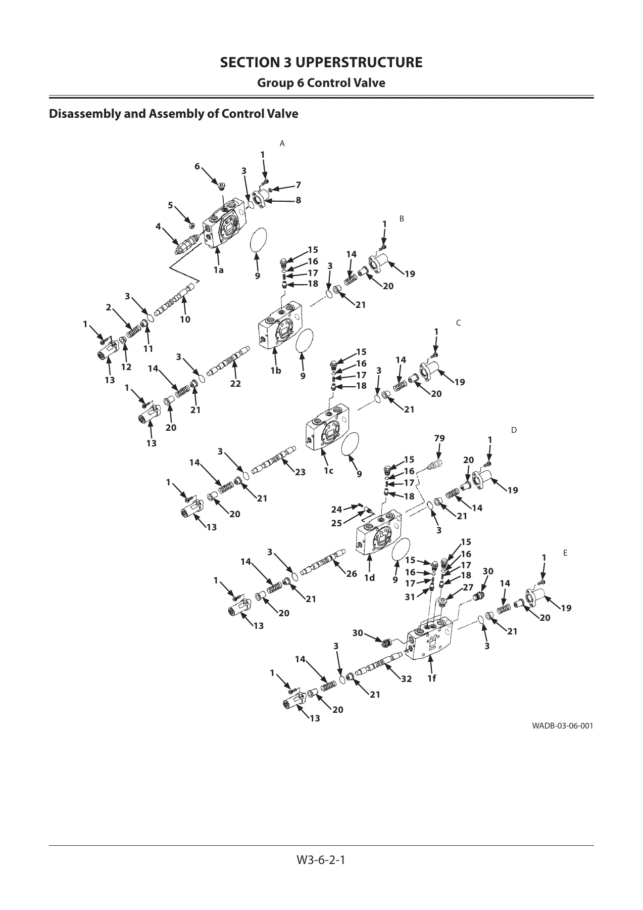
The upperstructure chapters walk through the removal and installation of the canopy, cab and counterweight, then move into the hydraulic hardware. The pump device is covered from removal through full disassembly and reassembly, including the order in which the body halves come apart and how the cylinder block assembly, plungers, retainer and valve plate are handled. The control valve is broken down by section letter — flow combiner, blade, swing, auxiliary, arm, travel right, travel left, boom and bucket — with separate procedures for the boom anti-drift valve, the spool, and the arm regenerative valve and orifice. Relief valves carry an explicit warning that they must not be disassembled because the pressure setting would be lost.
The swing device chapter separates the reduction gear from the swing motor and gives the bearing preload procedure for the shaft using the specified special tool, plus the assembly order for the first and second stage carriers and planetary gears. The pilot valve chapters cover the left and right control levers, the travel pilot valve, the blade pilot valve and the boom swing pilot valve, including how the spools are matched to their bores, how the shims are kept with their original ports, and how the cam-to-pusher clearance is checked.
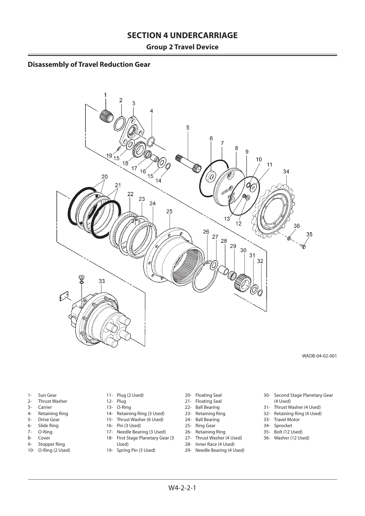
Undercarriage coverage is equally detailed. The travel reduction gear, travel motor and brake valve each have their own disassembly and assembly sequences, along with a dedicated floating seal section explaining correct O-ring seating, how to check that the sliding surface is parallel with the seal mating surface, and what happens if it is twisted or bent during installation. The center joint, track adjuster, front idler, upper and lower rollers, track and blade cylinder are all covered through to the last seal.
Tightening, Sealing and Pressure Release
Section 1 alone is worth the price of admission for anyone doing regular work on this machine. It carries a specified tightening torque chart across the bolt diameter range, the correct tightening orders for circular and rectangular bolt patterns, the rules for split flange assembly, and the locking methods — lock plates, split pins and wire — with the correct and incorrect examples shown side by side. There are separate torque tables for union joints, pipe joints, O-ring seal joints and screw-in connections, plus the clamp torque for T-bolt and worm-gear band clamps.
The bleeding procedures cover the hydraulic oil tank under vacuum, the pump, the travel motor and swing motor, the hydraulic circuit, the fuel system and the radiator. The pressure release procedure for the hydraulic circuit is written out step by step, including the warning not to loosen the overload relief valve body more than three-quarters of a turn, and the note that the lock nut and adjusting screw must not be turned or the setting changes.
Maintenance Standards and Wear Limits
Section 2 is where you find the numbers that decide whether a part goes back on the machine or into the scrap bin. The pump and swing motor section gives the allowable clearance between the plunger outer diameter and the cylinder block bore, the clearance between the plunger and the shoe bottom, and the wear limit on the oil seal mounting surface. The undercarriage section covers sprocket dimensions with standard and allowable limit columns and the remedy for each, front idler axle and bushing diameters with flange thickness limits, upper and lower roller dimensions, and the rubber crawler inspection rules — crack depth limits on the lug base and between lugs, when a crack reaching the steel code or steel core demands immediate repair, and the minimum lug height before the crawler has to be replaced as an assembly.
The front attachment section lists every pin and bushing in the linkage with its standard dimension, allowable limit and the remedy, so a worn boom, arm, bucket or blade pivot can be measured and judged against the factory figure rather than a guess. Cylinder rod bend and run-out limits are given alongside the recommended rod sizes after re-manufacturing.
Safety and Reference Material
The manual opens with a safety chapter covering signal words and alert symbols, protective clothing, machine inspection, cab precautions, handrails and steps, seat adjustment, seat belt use, safe travel and operation, working near excavations and slopes, power line clearances, lightning, object handling, flying debris, safe parking, fluid handling, fire prevention and evacuation, battery and refrigerant precautions, welding and grinding precautions, and correct waste disposal. A symbol and abbreviation table decodes the shorthand used throughout, and a unit conversion table covers length, volume, weight, force, torque, pressure, power, temperature, velocity and flow rate between SI, MKSA and English units. A service manual revision request form is included at the back for reporting errors or omissions.
Who This Workshop Manual Is For
This is the book for the person holding the wrench. Independent shops servicing Hitachi compact excavators, fleet maintenance departments running ZX38U-5A machines, and owner-operators who do their own hydraulic and undercarriage work will all find the same thing here — the sequence the factory uses to strip and rebuild each assembly, the torque to apply, the seal to replace, the clearance to measure and the limit that tells you the part is finished. It is not a sales brochure and it is not a quick-reference card; it is the full workshop procedure, and it assumes you have the tools and the patience to follow it.
IMAGES PREVIEW
Instant PDF Delivery
The Hitachi ZX38U-5A Hydraulic Excavator Workshop Manual is delivered as a PDF the moment payment clears. There is no shipping, no waiting for a parcel and no risk of a printed copy going missing in the shop. The file opens on a laptop, tablet or phone, so it can sit on the bench next to the machine or on a screen in the cab, and any page or torque chart can be printed and taken under the machine where it is needed. Whether the job in front of you is a swing motor reseal, a travel device rebuild, a control valve strip-down or simply checking a pin against its wear limit, the procedure and the number are in the same document.


Reviews
There are no reviews yet.