Hitachi ZX470-5B ZX470LC-5B ZX470H-5B ZX470LCH-5B ZX470R-5B ZX470LCR-5B ZX520LCH-5B Hydraulic Excavator Troubleshooting Manual (TTJAA-EN-01) – PDF Download
Original price was: $86.95.$27.95Current price is: $27.95.
- Hitachi ZX470-5B ZX470LC-5B ZX470H-5B ZX470LCH-5B ZX470R-5B ZX470LCR-5B ZX520LCH-5B Hydraulic Excavator Technical Troubleshooting Manual
- Part No:TTJAA-EN-01
Description
Hitachi ZX470-5B ZX470LC-5B ZX470H-5B ZX470LCH-5B ZX470R-5B ZX470LCR-5B ZX520LCH-5B Hydraulic Excavator Technical Troubleshooting Manual (TTJAA-EN-01)
File Details:
Hitachi ZX470-5B ZX470LC-5B ZX470H-5B ZX470LCH-5B ZX470R-5B ZX470LCR-5B ZX520LCH-5B Hydraulic Excavator Technical Troubleshooting Manual (TTJAA-EN-01)
- Manual Language:English
- Pages: 518
- Size: 4.59 MB
- Format:PDF
- Downloadable:Yes
HITACHI ZX470-5B ZX470LC-5B ZX470H-5B ZX470LCH-5B ZX470R-5B ZX470LCR-5B ZX520LCH-5B HYDRAULIC EXCAVATOR TROUBLESHOOTING MANUAL (TTJAA-EN-01) – PDF DOWNLOAD:
Image Preview:
Description:
Hitachi ZX470-5B ZX470LC-5B ZX470H-5B ZX470LCH-5B ZX470R-5B ZX470LCR-5B ZX520LCH-5B Hydraulic Excavator Technical Troubleshooting Manual (TTJAA-EN-01)
TO THE READER
• This manual is written for an experienced technician to provide technical information needed to maintain and repair this machine.
• Be sure to thoroughly read this manual for correct product information and service procedures.
• If you have any questions or comments, at if you found any errors regarding the contents of this manual, please contact using “Service Manual Revision Request Form” at the end of this manual.
ADDITIONAL REFERENCES
• Please refer to the other materials (operator’s manual, parts catalog, engine technical material and Hitachi training material etc.) in addition to this manual.
MANUAL COMPOSITION
• This manual consists the Technical Manual and the Workshop Manual.
• Information included in the Technical Manual: technical information needed for redelivery and delivery, operation and activation of all devices and systems, operational performance tests, and troubleshooting procedures.
• Information included in the Workshop Manual: technical information needed for maintenance and repair of the machine, tools and devices needed for maintenance and repair, maintenance standards, and removal/installation and assemble/ disassemble procedures.
Table Of Contents:
Hitachi ZX470-5B ZX470LC-5B ZX470H-5B ZX470LCH-5B ZX470R-5B ZX470LCR-5B ZX520LCH-5B Hydraulic Excavator Technical Troubleshooting Manual (TTJAA-EN-01)
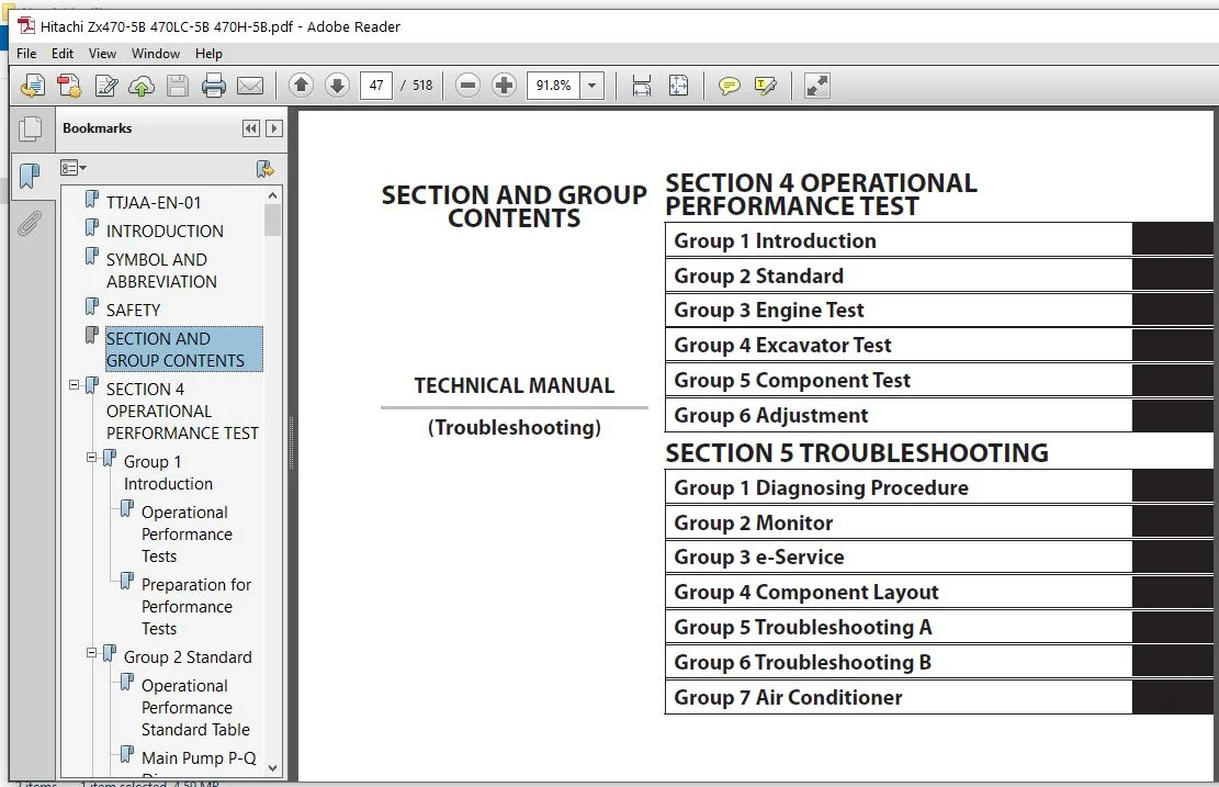
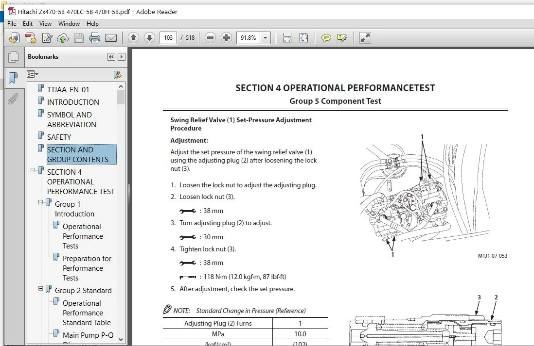
TTJAA-EN-01.................................................................................  1
INTRODUCTION................................................................................  3
SYMBOL AND ABBREVIATION.....................................................................  5
SAFETY......................................................................................  7
SECTION AND GROUP CONTENTS.................................................................. 47
SECTION 4 OPERATIONAL PERFORMANCE TEST...................................................... 49
	Group 1 Introduction.................................................................... 51
		Operational Performance Tests....................................................... 51
		Preparation for Performance Tests................................................... 52
	Group 2 Standard........................................................................ 53
		Operational Performance Standard Table.............................................. 53
		Main Pump P-Q Diagram............................................................... 57
		Fan Pump P-Q Diagram................................................................ 58
		MPDR. Monitor Indicating Values (MC)................................................ 60
		MPDr. Monitor Indicating Values (ECM)............................................... 66
		Sensor Activating Range............................................................. 67
	Group 3 Engine Test..................................................................... 69
		Engine Speed........................................................................ 69
		Lubricant Consumption............................................................... 72
	Group 4 Machine Performance Test........................................................ 73
		Travel Speed........................................................................ 73
		Mistrack Check...................................................................... 75
		Travel Motor Leakage................................................................ 76
		Swing Speed......................................................................... 77
		Swing Function Drift Check.......................................................... 78
		Swing Motor Leakage................................................................. 79
		Maximum Swingable Slant Angle....................................................... 80
		Swing Bearing Play.................................................................. 82
		Hydraulic Cylinder Cycle Time....................................................... 84
		Dig Function Drift Check............................................................ 86
		Control Lever Operating Force....................................................... 87
		Control Lever Stroke................................................................ 88
		Boom Raise/Swing Combined Operation Check........................................... 89
	Group 5 Component Test.................................................................. 91
		Primary Pilot Pressure.............................................................. 91
		Secondary Pilot Pressure............................................................ 93
		4-Spool Solenoid Valve Set Pressure................................................. 94
		2-Spool Solenoid Valve Set Pressure................................................. 95
		Main Pump Delivery Pressure......................................................... 97
		Fan Pump Delivery Pressure.......................................................... 98
		Main Relief Valve Set Pressure...................................................... 99
		Overload Relief Valve Set Pressure..................................................105
		Main Pump Flow Rate Measurement.....................................................110
		Fan Pump Flow Rate Measurement......................................................116
		Swing Motor Drainage................................................................122
		Travel Motor Drainage...............................................................124
	Group 6 Adjustment......................................................................127
		Pump Learning.......................................................................127
		Torque Adjustment...................................................................128
		Connection..........................................................................129
		Measuring Method of No-Load-Max Differential Pressure...............................130
		Muffler Filter Differential Pressure Sensor Learning................................132
		Rewrite of Muffler Filter Serial No.................................................133
		Maintenance of Muffler Filter.......................................................134
SECTION 5 TROUBLESHOOTING...................................................................137
	Group 1 Diagnosing Procedure............................................................139
		Introduction........................................................................139
		Diagnosis Procedure.................................................................140
		Electric System Inspection..........................................................143
		Precautions for Inspection and Maintenance..........................................144
		Instructions for Disconnecting Connectors...........................................146
		Fuse Inspection.....................................................................148
		Fusible Link Inspection.............................................................151
		Battery Voltage Check...............................................................152
		Alternator Check....................................................................153
		Continuity Check....................................................................154
		Voltage and Current Measurement.....................................................156
		Check by False Signal...............................................................163
		Test Harness........................................................................164
	Group 2 Monitor.........................................................................167
		Outline.............................................................................167
		Operating Procedures of Service Menu (Built-In Diagnosing System)...................168
		Inspection of Engine Oil Level, Hour Meter and Fuel Gauge...........................200
		Fuel Gauge and Coolant Temperature Gauge............................................201
	Group 3 e-Service.......................................................................203
		Outline.............................................................................203
		List of Operation Data..............................................................204
		Snapshot Data.......................................................................208
		Communication System................................................................209
	Group 4 Component Layout................................................................211
		Main Component......................................................................211
		Electrical System (Overview)........................................................213
		Electrical System (Rear Tray).......................................................214
		Electrical System (Switch Panel)....................................................215
		Electrical System (Cab Behind Side).................................................216
		Engine 1............................................................................218
		Engine 2............................................................................219
		Muffler Filter......................................................................220
		Pump Device.........................................................................221
		Control Valve.......................................................................222
		Check Valve.........................................................................224
		Signal Control Valve................................................................224
		4-Spool Solenoid Valve Unit.........................................................227
		2-Spool Solenoid Valve Unit.........................................................227
		Layout of Attachment Spec. Parts (Hydraulic System).................................228
		Layout of Control Valve.............................................................232
		Pilot Port (Signal Control Valve)...................................................248
	Group 5 Troubleshooting A...............................................................253
		Troubleshooting A (Base Machine Diagnosis by Using Fault Codes) Procedure...........253
		MC Fault Code List..................................................................255
		ECM Fault Code List.................................................................278
		Monitor Controller (Information) Fault Code List....................................310
		Communication Terminal Fault Code List..............................................312
		Electrical Lever (Optional) Fault Code List.........................................313
		MC Fault Codes 11000 to 11002.......................................................318
		MC Fault Code 11003.................................................................320
		MC Fault Codes 11004, 11006, 11007, 11009...........................................322
		CAN0 Harness Check..................................................................323
		CAN0 (Engine) Harness Check.........................................................326
		MC Fault Codes 11005, 11008, 11010..................................................328
		CAN1 Harness Check..................................................................329
		MC Fault Code 11100.................................................................332
		MC Fault Code 11101.................................................................333
		MC Fault Codes 11200, 11202.........................................................334
		MC Fault Codes 11301, 11302.........................................................335
		MC Fault Code 11303.................................................................336
		MC Fault Codes 11304, 11325.........................................................337
		MC Fault Code 11405.................................................................338
		MC Fault Code 11408.................................................................339
		MC Fault Code 11412.................................................................340
		MC Fault Code 11428.................................................................341
		MC Fault Code 11802.................................................................342
		MC Fault Code 11901.................................................................343
		MC Fault Codes 11910, 11911, 11914, 11918, 11920....................................344
		MC Fault Codes 11942, 11943.........................................................345
		MC Fault Codes 11944, 11945.........................................................346
		MC Fault Code 11946.................................................................347
		CAN0 Harness Check..................................................................348
		MC Fault Code 11947.................................................................351
		CAN1 Harness Check..................................................................352
		MC Fault Code 11948.................................................................355
		MC Fault Code 11950.................................................................356
		MC Fault Code 11951.................................................................357
		MC Fault Code 11952 (670, 870)......................................................358
		MC Fault Code 11953.................................................................359
		MC Fault Codes 11971, 11972.........................................................360
		MC Fault Codes 11974, 11975.........................................................361
		MC Fault Codes 11978, 11979.........................................................362
		MC Fault Code 11981.................................................................363
		MC Fault Code 11982.................................................................364
		MC Fault Codes 11983, 11984.........................................................365
		MC Fault Codes 11985, 11986.........................................................366
		MC Fault Code 11989.................................................................367
		MC Fault Codes 11992, 11994.........................................................368
		MC Fault Codes 11995, 11997.........................................................369
		MC Fault Code 11998.................................................................370
		MC Fault Codes 20000, 20003, 20005, 20006, 20008....................................371
		MC Fault Codes 20009, 20010, 20062..................................................372
		Monitor Controller (Monitor) Fault Codes 20100 to 20106.............................373
		Monitor Controller (Monitor) Fault Codes 20109 to 20149.............................374
	Group 6 Troubleshooting B...............................................................375
		Troubleshooting B (Machine Diagnosis by Using Troubleshooting Symptom) Procedure....375
		Relationship Between Machine Trouble Symptoms and Related Parts.....................377
		Correlation Between Trouble Symptoms and Part Failures..............................404
		Engine System Troubleshooting.......................................................423
		All Actuator System Troubleshooting.................................................431
		Front Attachment System Troubleshooting.............................................440
		Swing System Troubleshooting........................................................453
		Travel System Troubleshooting.......................................................456
		Other System Troubleshooting........................................................460
		Exchange Inspection.................................................................467
		How to Lowering Boom in Case of Emergency and When Engine Stops.....................470
	Group 7 Air Conditioner.................................................................471
		Outline.............................................................................471
		Functions of Main Parts.............................................................474
		Troubleshooting.....................................................................479
		Air Conditioner Controller Fault Code List..........................................480
		Air Conditioner Controller Fault Codes 11 to 22.....................................481
		Air Conditioner Controller Fault Codes 43 to 92.....................................482
		Work after Replacing Components.....................................................504
		Refill Compressor Oil...............................................................505
		Charge Air Conditioner with Refrigerant.............................................506
		Hose and Pipe Tightening Torque.....................................................514
SERVICE MANUAL REVISION REQUEST FORM........................................................517
The Attached Diagram List...................................................................518
Please Note:
⦁ This is not a physical manual but a digital manual – meaning no physical copy will be couriered to you. The manual can be yours in the next 2 mins as once you make the payment, you will be directed to the download page IMMEDIATELY.
⦁ This is the same manual used by the dealers inorder to diagnose your vehicle of its faults.
⦁ Require some other service manual or have any queries: please WRITE to us at [email protected]

Ishaan Neil –
Processing was quick