
Hitachi ZX470-5G ZX470LC-5G ZX470H-5G ZX470LCH-5G ZX470R-5G ZX470LCR-5G Hydraulic Excavator Workshop Manual
Original price was: $49.95.$29.95Current price is: $29.95.
Complete workshop and engine service reference for Hitachi ZX470-5G, ZX470LC-5G, ZX470H-5G, ZX470LCH-5G, ZX470R-5G and ZX470LCR-5G hydraulic excavators. Covers maintenance standards, removal and installation, component disassembly and assembly, tightening data, hydraulic service work, undercarriage, front attachment and 6WG1 engine service information.
Description
Hitachi ZX470-5G ZX470LC-5G ZX470H-5G ZX470LCH-5G ZX470R-5G ZX470LCR-5G Hydraulic Excavator Workshop Manual
The Hitachi ZX470-5G ZX470LC-5G ZX470H-5G ZX470LCH-5G ZX470R-5G ZX470LCR-5G Hydraulic Excavator Workshop Manual is a detailed technical service reference for maintenance and repair of the six excavator models identified on the manual cover. Part No. WJAC-EN-00 combines workshop procedures with extensive engine and accessory information, giving experienced technicians a structured source for machine disassembly, assembly, component removal and installation, maintenance standards, tightening specifications and engine servicing.
The workshop material goes far beyond routine operator maintenance. It follows major machine assemblies through upperstructure, undercarriage and front attachment work, with illustrated procedures, component weights, special-tool references, tightening torques and service cautions. Maintenance-standard sections provide measured dimensions and allowable limits for deciding whether components remain serviceable, need adjustment or require repair or replacement. The engine portion adds specifications and service procedures for the 6WG1 family, including the 6WG1TQA data and AA-6WG1TQA performance information shown in the manual.
File Details
- Manual type: Hydraulic Excavator Workshop Manual
- Brand: Hitachi
- Models: ZX470-5G, ZX470LC-5G, ZX470H-5G, ZX470LCH-5G, ZX470R-5G, ZX470LCR-5G
- Language: English
- Page count: 878 pages
- File format: PDF
- Part number: WJAC-EN-00
- Printed: 2012, 02
- Publisher shown: Hitachi Construction Machinery Co., Ltd.
Workshop Procedures and Service Standards
This Hitachi ZX470-5G workshop manual starts with the practical rules needed before major service work. It explains precautions for disassembling and assembling, inspection before dismantling, identification and storage of removed parts, handling of seals and O-rings, use of designated tools, floating-seal installation and lifting with nylon slings. General tightening information includes bolt and nut torque charts, tightening order, split-flange precautions, pipe and hose joints, O-ring seal joints, quick couplings, screw-in connections and hose-clamp tightening.
Hydraulic preparation procedures cover bleeding air from the hydraulic oil tank, hydraulic system, fuel system and radiator, together with the hydraulic-circuit pressure release procedure and preparation before inspection and maintenance. These sections are particularly useful when components such as pumps, motors, cylinders, tanks or hydraulic lines have been removed and installed because the manual gives the sequence required before returning the machine to operation.
The maintenance-standard section supplies inspection dimensions and allowable limits rather than only removal instructions. It includes main pump and swing motor clearances, travel motor checks, sprocket dimensions, center-joint wear criteria, front idler and roller measurements, track link and pin dimensions, front-attachment pin and bushing standards, side cutter and point limits, arm-to-bucket and arm-to-boom connection dimensions, and cylinder rod service measurements. These values help a technician compare an inspected component against the manual’s stated standard or allowable limit before deciding on further repair.
Upperstructure, Hydraulic Components and Major Machine Assemblies
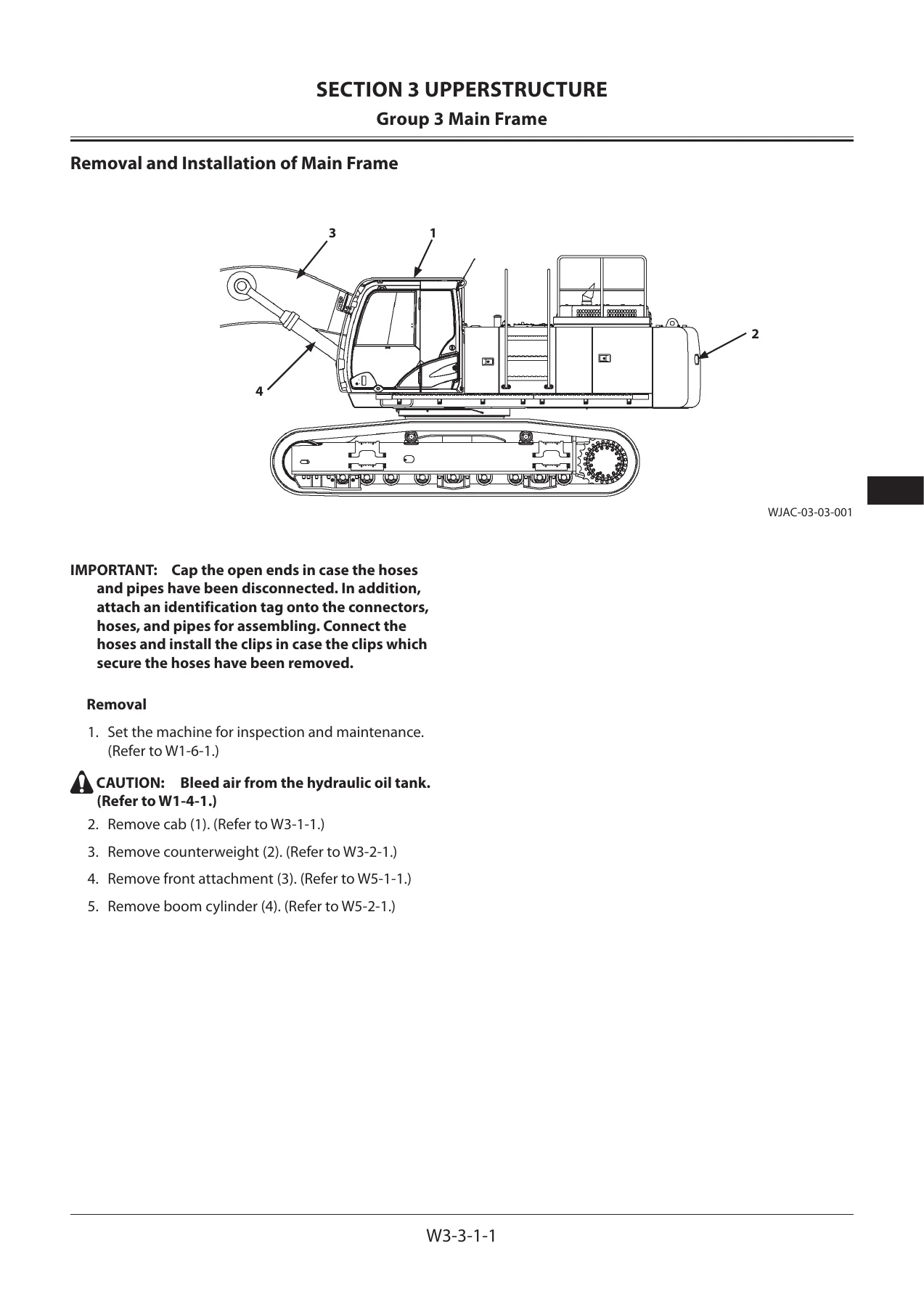
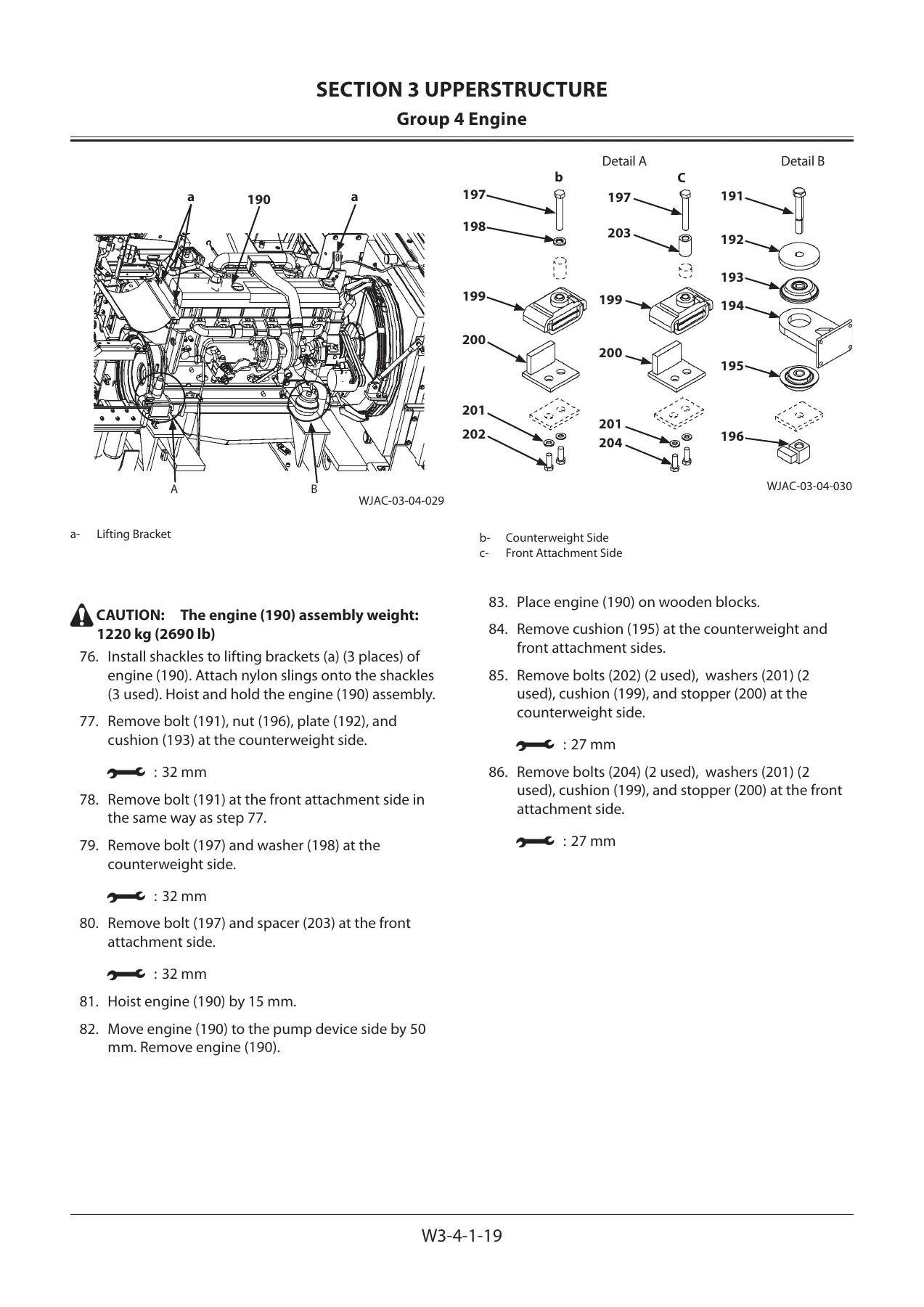
A large portion of the Hitachi ZX470LC-5G workshop manual is devoted to major upperstructure service work. Cab procedures include cab removal and installation as well as detailed glass dimensions and glass replacement instructions. Separate procedures cover the counterweight, main frame, engine, radiator assembly, hydraulic oil tank and fuel tank. The illustrations identify fasteners, hoses, connectors, lifting points and component positions, while the procedure text specifies tools, component weights and installation torques where required.
Hydraulic component coverage extends to the pump device, control valve, swing device, pilot valves, solenoid valves, signal control valve and shockless valve. The pump section includes main-pump removal and installation, disassembly and assembly, regulator work, and the structure of the pilot pump and sensor. Control-valve material covers removal and installation plus valve-unit and spool-side disassembly and assembly. Swing-device coverage includes the swing device and swing motor, while pilot-valve chapters address left, right and travel pilot valves with disassembly and assembly procedures.
Undercarriage and Front Attachment Repair
The undercarriage section is arranged around the assemblies that receive heavy wear in excavator service. Swing-bearing procedures cover removal, installation, disassembly and assembly. Travel-device material includes removal and installation of the travel device, travel-device disassembly and assembly, travel motor procedures, and brake-valve disassembly and assembly. The center joint, track adjuster and front idler each receive their own removal, installation and overhaul coverage. Upper and lower roller procedures and track removal and installation complete the section, with special-tool instructions and component-weight cautions included where the job requires them.
Front-attachment work covers removal and installation of the complete attachment and replacement of attachment bushings. Separate boom, arm and bucket cylinder chapters provide removal and installation procedures followed by disassembly and assembly instructions. The cylinder overhaul material identifies internal parts such as cylinder rods, heads, bushings, seals, backup rings, slide rings, pistons and cylinder tubes and provides specified assembly torques and special-tool references throughout the repair sequence.
6WG1 Engine and Accessory Service Coverage
The engine portion makes this Hitachi ZX470H-5G ZX470LCH-5G workshop manual substantially more useful for jobs that extend beyond the excavator chassis. Its general-information chapter includes repair instructions, bolt tightening methods, standard torque specifications, thread-locking agents, main engine data, performance information, service standards, torque specifications, special tools, troubleshooting, lubricant application and sealant application. Engine identification information shows the 6WG1 designation, while the main data table identifies 6WG1TQA and the performance section identifies model AA-6WG1TQA.
Engine mechanical coverage includes the fan center, turbocharger, exhaust and inlet manifolds, water pump, alternator, oil cooler, injection pump, coupling assembly, cylinder head, rocker arm and shaft assembly, camshaft, timing gears, flywheel housing, oil pan, piston, crankshaft, crank pulley, flywheel and cylinder block. Service information also covers lubrication and fuel systems, cooling, valve-clearance adjustment, compression-pressure measurement, recommended lubricants and engine-oil viscosity.
Further engine chapters address cooling-system work on the water pump and thermostat; fuel-system service for the fuel filter, injection nozzle holder and injection pump; starting and charging procedures for the alternator and starter motor; engine lubrication including the oil pump and oil cooler; and engine induction with turbocharger service. This gives the manual a broad service scope from excavator structures and hydraulic components through internal engine inspection and repair.
Chapters Covered
- Section 1 – General Information: precautions for disassembling and assembling; tightening bolts and nuts; piping joints; painting specifications and final painted colors; bleeding air from the hydraulic oil tank, hydraulic system, fuel system and radiator; hydraulic circuit pressure release; preparation before inspection and maintenance.
- Section 2 – Maintenance Standard: main pump and swing motor; travel motor, sprocket, center joint, front idler, upper roller, lower roller and track; front-attachment bushings, pins, side cutter, point, arm and bucket connection, arm and boom connection, and cylinder standards.
- Section 3 – Upperstructure: cab and cab glass; counterweight; main frame; engine; radiator assembly; hydraulic oil tank; fuel tank; pump device; control valve; swing device and swing motor; pilot valves; solenoid valves; signal control valve; shockless valve.
- Section 4 – Undercarriage: swing bearing removal, installation and overhaul; travel device, travel motor and brake valve; center joint; track adjuster; front idler; upper and lower rollers; track removal and installation.
- Section 5 – Front Attachment: front attachment removal and installation; bushing replacement; boom cylinder, arm cylinder and bucket cylinder removal and installation; cylinder disassembly and assembly.
- Section 6 – Engine and Accessory: general engine information and specifications; service information; engine mechanical; engine cooling; engine fuel; starting and charging; engine lubrication; engine induction and turbocharger service.
Taken together, these chapters provide the service information needed to approach both complete-assembly jobs and detailed component repairs. The manual combines step-by-step procedures with measurement standards, specified torques, illustrated component locations and special-tool references, allowing the technician to follow the documented sequence rather than relying on memory when dismantling and rebuilding large excavator systems.
Repair With the Correct Procedures and Specifications
The Hitachi ZX470-5G ZX470LC-5G ZX470H-5G ZX470LCH-5G ZX470R-5G ZX470LCR-5G Hydraulic Excavator Workshop Manual supports demanding service work including upperstructure removal, hydraulic component overhaul, undercarriage repair, front-attachment and cylinder work, engine removal and installation, internal engine service and inspection against specified maintenance limits. Having the documented procedures, tightening values, component weights, service limits and assembly instructions available during a repair helps reduce uncertainty and provides a consistent reference for carrying out each job in the intended sequence.
Delivered instantly as a PDF after payment with no physical shipping required. The manual can be viewed on compatible phones, tablets and computers and pages can be printed when a paper reference is more convenient at the machine or workbench.
Reviews
There are no reviews yet.