
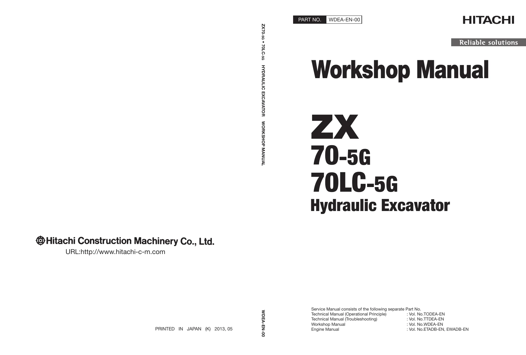
Hitachi ZX70-5G ZX70LC-5G Hydraulic Excavator Workshop Manual PDF
Original price was: $39.95.$24.95Current price is: $24.95.
Complete Hitachi workshop manual for the ZX70-5G and ZX70LC-5G hydraulic excavators — general service data, maintenance standards, upperstructure, undercarriage and front attachment removal, disassembly and assembly procedures in a 428-page PDF.
Description
Hitachi ZX70-5G / ZX70LC-5G Workshop Manual — Removal, Disassembly and Assembly
This is the Hitachi workshop manual issued for the ZX70-5G, ZX70LC-5G and 70-5G hydraulic excavators, published under document code WDEA EN 00 with a 2014 revision date. It is the bench-side half of Hitachi’s service documentation set: where a technical manual explains how a system works and how to troubleshoot it, this Hitachi ZX70-5G ZX70LC-5G hydraulic excavator workshop manual tells you how to physically take the machine apart, what it should measure when you get there, and how to put it back together to specification.
Anyone who has pulled a swing device or a travel motor on a mini excavator knows the job lives or dies on the details — the bolt torque, the matching marks, the direction a spring pin is driven, the sealant bead you forgot. That is the layer of information this manual provides, page after page, for the whole machine.
File Details
- Manual type: Workshop Manual (removal/installation, disassembly/assembly, maintenance standard)
- Brand: Hitachi Construction Machinery
- Models covered: ZX70-5G, ZX70LC-5G, 70-5G hydraulic excavator
- Document number: WDEA EN 00
- Revision date shown: 2014-04-11
- Language: English
- Page count: 428 pages
- File format: PDF
Chapters Covered
The document is divided into five sections, each with numbered groups:
- Section 1 — General
- Group 1: Precautions for disassembling and assembling
- Group 2: Tightening — bolt and nut torque charts, piping joints, union joints, O-ring seal joints, quick couplings, screw-in connections, hose clamps, lock plates, split pins and locking wire
- Group 3: Painting — surface and final paint specifications
- Group 4: Bleeding air — hydraulic oil tank, hydraulic system, fuel system, radiator
- Group 5: Pressure release procedure for the hydraulic circuit
- Group 6: Preparation before inspection and maintenance
- Section 2 — Maintenance Standard
- Group 1: Main pumps 1, 2 and main pump 3 clearances, spring free lengths, shoe thickness, swing motor
- Group 2: Travel motor, parking brake, sprocket, front idler, upper and lower rollers, track link and grouser shoe wear limits
- Group 3: Pin and bushing wear limits, side cutter, bucket point, arm and bucket connection dimensions, cylinder rod bend and run-out
- Section 3 — Upperstructure
- Group 1: Cab removal and installation, cab glass dimensions and replacement
- Group 2: Counterweight
- Group 3: Main frame
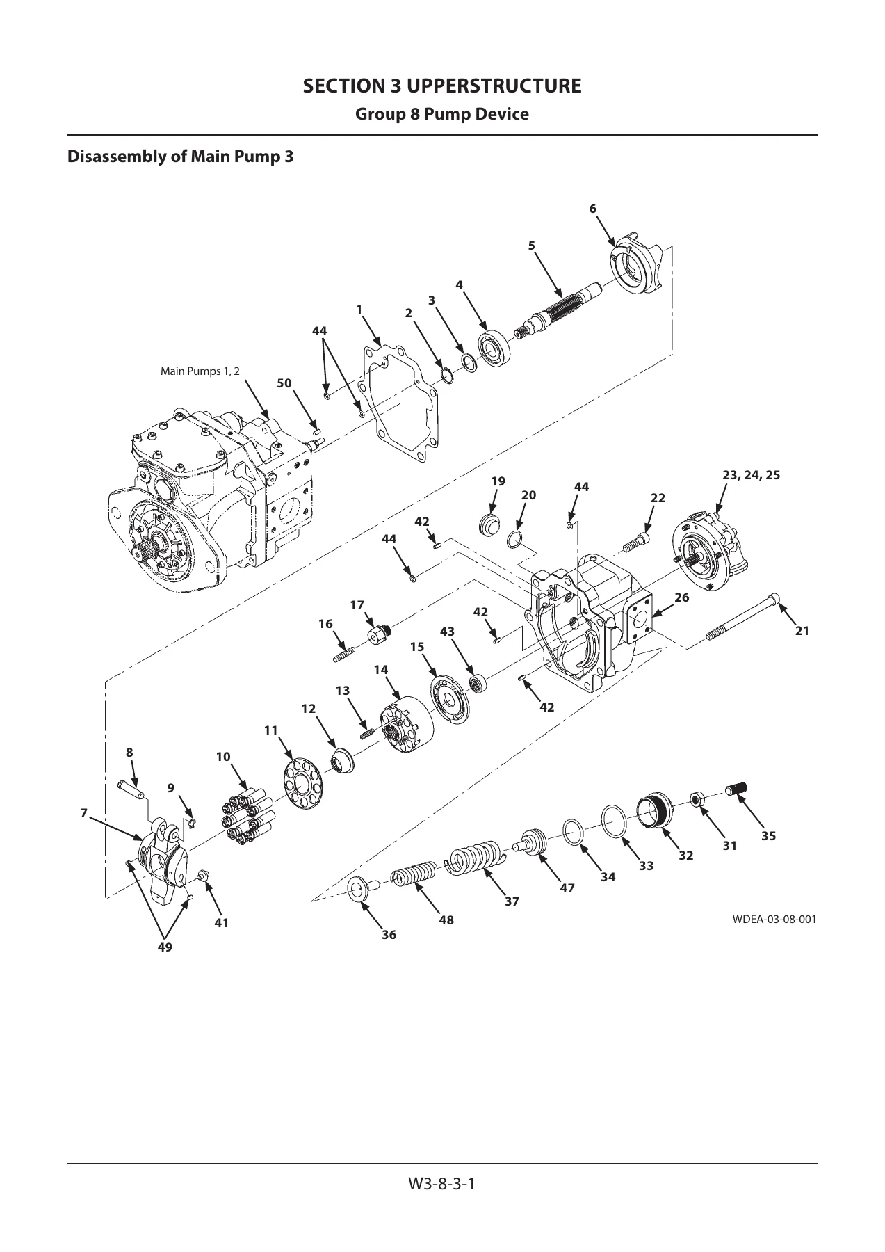
- Group 8: Pump device — main pump 3, main pumps 1 and 2, gear pump assembly
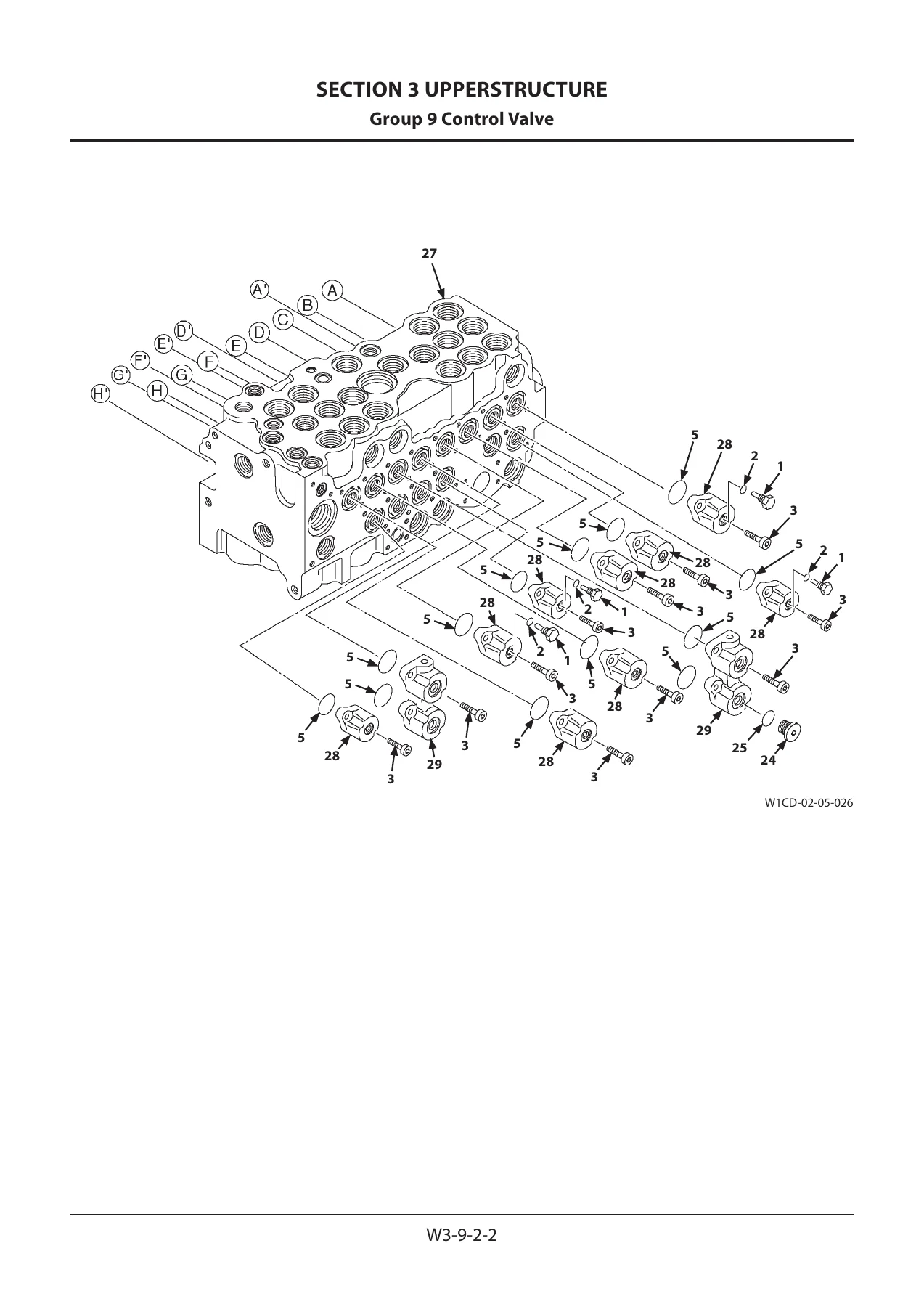
- Group 9: Control valve — disassembly and assembly of spools, relief valves, load check valves, anti-drift valve
- Group 10: Swing device, swing motor and valve structure
- Group 11: Pilot valves (left, right and travel) and their disassembly/assembly
- Group 12: Solenoid valve unit and proportional solenoid valve
- Group 13: Pilot shut-off valve
- Group 14: Shockless valve
- Section 4 — Undercarriage
- Group 1: Swing bearing removal, installation, disassembly and assembly
- Group 2: Travel device — travel reduction gear, travel motor, brake valve, floating seal precautions
- Group 3: Center joint, including body replacement
- Group 4: Track adjuster
- Group 5: Front idler
- Group 6: Upper and lower rollers
- Group 7: Track removal and installation
- Section 5 — Front Attachment
- Group 1: Front attachment removal and installation
- Group 2: Boom, arm and bucket cylinder removal, installation, disassembly and assembly
Read together, these sections give a technician a complete teardown and rebuild path for the machine. The general section establishes the working rules — how Hitachi wants fasteners lubricated before torquing, how split flange and union joints are sealed, how air is bled from each circuit, and how residual pressure is released safely before a line is opened. The maintenance standard section then supplies the numbers those procedures are judged against: piston-to-cylinder block clearance, shoe thickness, spring free length, track link pitch elongation, pin and bushing wear limits and the point at which a part is replaced rather than reused.
The upperstructure and undercarriage sections are the working heart of the book. Each component group is handled as a sequence — removal from the machine, disassembly on the bench, inspection against the standard, then assembly and installation with the torque figures, thread lockers, sealants and special tools named at each step. Exploded illustrations accompany the major assemblies, including the control valve, swing device, travel motor and brake valve, so the order of parts is visible as well as described. The front attachment section closes the manual with the boom, arm and bucket cylinder procedures, including nut torque, set screw crimping and cylinder head tightening values.
What This Manual Lets You Do
With this Hitachi ZX70-5G ZX70LC-5G workshop manual on hand you can carry out a full component-level rebuild rather than swapping whole assemblies. That includes pulling and resealing a boom, arm or bucket cylinder; rebuilding a travel reduction gear or travel motor; disassembling the control valve to reach a sticking spool or a failed load check valve; replacing a swing bearing; re-shimming a swing device bearing preload; resealing a center joint; and servicing the track adjuster, front idler and rollers.
The reason the correct document matters here is that most of these assemblies are held together with values that are not guessable. Bearing nut preload on the swing device, cylinder head torque on each of the three cylinders, control valve cover bolts, travel device mounting bolts, sprocket bolts — all are specified, and several steps depend on sequence rather than force, such as fitting a valve plate groove over a spring pin or installing a spring pin assembly with its slits facing opposite directions. Following the manual keeps those details right the first time.
The maintenance standard tables also let you make an informed reuse-or-replace decision instead of defaulting to new parts, which matters on wear items like pins, bushings, rollers and track links where the wear limit is the only real guide.
Delivery
IMAGES PREVIEW
The manual is delivered as an instant PDF download — no shipping, no waiting for a parcel, and no risk of a paper copy going missing in a workshop. Once the file is on your device you can open it on a laptop, tablet or phone at the machine, or print just the pages for the job in front of you and keep the rest clean. Keep a copy on the shop computer and another on a phone, and the right procedure is always within reach.


Reviews
There are no reviews yet.