
Hitachi ZX85USB-7 Hydraulic Excavator Technical Manual Operational Principle TODEU90-EN-00
Original price was: $34.95.$20.95Current price is: $20.95.
Hitachi ZX85USB-7 Technical Manual (Operational Principle), publication TODEU90-EN-00 dated 22/12/2023. 269-page English PDF explaining controller, engine, hydraulic and electrical system operation plus pump, swing, control valve, pilot valve and travel device component principles.
Description
Hitachi ZX85USB-7 Hydraulic Excavator Technical Manual – Operational Principle
This is the Hitachi ZX85USB-7 Technical Manual devoted to the operational principle of the machine. Published by Hitachi Construction Machinery Co., Ltd. under document number TODEU90-EN-00 and dated 22/12/2023, it is written for the experienced technician and explains how the ZX85USB-7 actually works: how the controllers communicate over the CAN networks, how engine output and pump delivery are managed, how the hydraulic and electrical circuits are arranged, and how each component inside the pump, swing, control valve, pilot valve and travel devices performs its function.
File Details
- Manual type: Technical Manual – Operational Principle
- Brand: Hitachi Construction Machinery
- Model: ZX85USB-7 hydraulic excavator
- Publication number: TODEU90-EN-00
- Publication date: 22/12/2023
- Language: English
- Format: PDF
- Page count: 269 pages
Chapters Covered
-
Section 1 – General
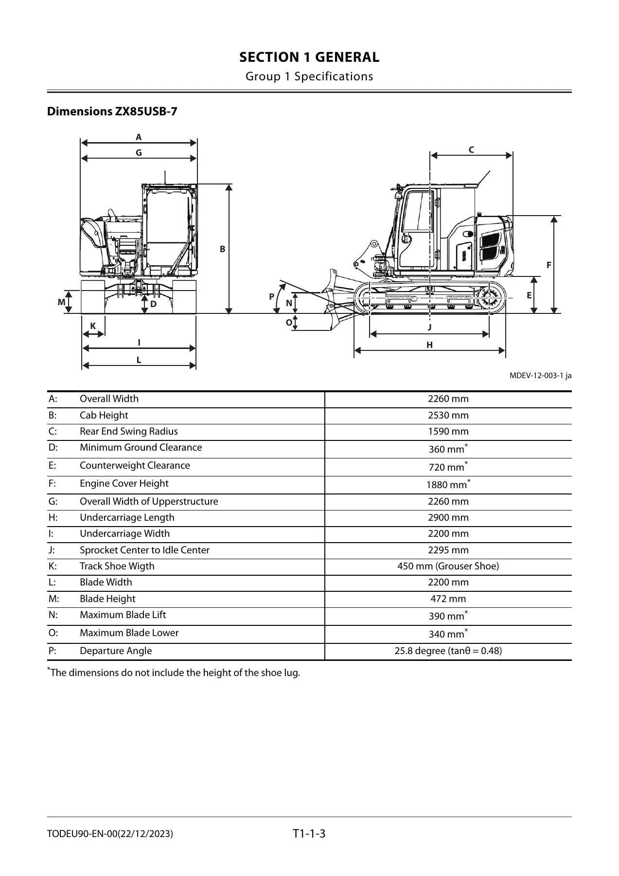
- Group 1: Specifications – ZX85USB-7 specifications, dimensions, work ranges and dimensions
- Group 2: Component Layout – main component, electrical system overview, rear tray, switches, utility space, relays, engine, aftertreatment device, pump device, around pump device, control valve, swing device, travel device, 2-spool solenoid valve unit, attachment spec parts, around control valve, control valve both sides, around uppertructure center, around boom rear, accumulator, secondary relief valve, option valve, auxiliary flow combiner valve, 5-spool solenoid valve unit, PTO valve, arm roll-in and bucket roll-in speed adjustment valves
- Group 3: Component Specifications – engine, engine accessories, hydraulic components, hydraulic components (option), electrical components
-
Section 2 – System
- Group 1: Controller – outline of controller, CAN circuit
- Group 2: Control System – engine control dial, ECO control, power mode switch control, ECO mode control, travel HP mode control, auto-idle control, engine speed slow down control, one-touch idle control, pump control, speed sensing control, pump torque decrease control, valve control (standard and option), travel motor displacement angle control, attachment flow rate control, work mode control, auto shut-down control, automatic engine stop at low temperature, hydraulic oil overheat alarm, breaker alarm, travel alarm, overload alarm
- Group 3: Engine System – ECU outline, fuel injection amount, timing, rate and pressure control, fuel injection amount correction, EGR control, preheating control, alarm control, engine output restriction control (inducement), NCD system, PCD system, aftertreatment device outline, operation and regeneration control
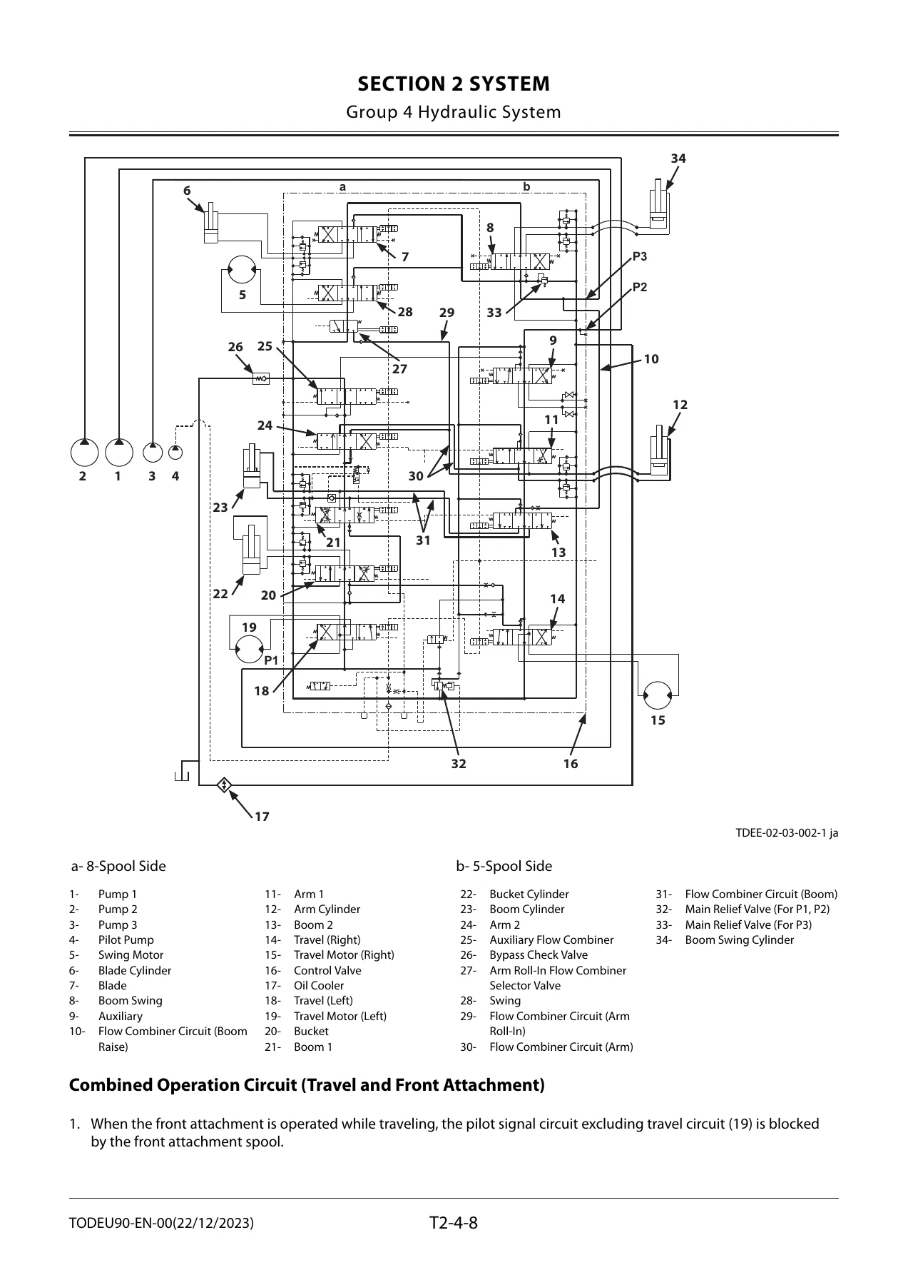
- Group 4: Hydraulic System – pilot circuit, operation control circuit, pump control circuit, valve control circuit, travel motor displacement angle control circuit, swing parking brake release circuit, main circuit, combined operation circuits
- Group 5: Electrical System – main circuit, power circuit, CAN circuit, accessory circuit, starting circuit, charging circuit, alternator and regulator operation, surge voltage prevention, pilot shut-off circuit, auto shut-down circuit, engine stop circuit, monitor circuit, security circuit, Aerial Angle circuit, radio and air conditioner circuits, accessory circuits
-
Section 3 – Component Operation
- Group 1: Pump Device – main pump operation, delivery flow rate increase and decrease, pumps 1 and 2 regulator and control functions, pump 3 regulator, pilot pump
- Group 2: Swing Device – swing reduction gear, swing motor, swing parking brake, valve unit, make-up valve, swing relief valve
- Group 3: Control Valve – components, hydraulic circuit, main circuit, pilot operation control circuit, pilot signal circuit, flow combiner valve, main relief pressure selection, boom anti-drift valve, main relief valve, overload relief valve with make-up function
- Group 4: Pilot Valve – front attachment/swing, travel, blade, auxiliary, boom swing and positioning pilot valves and the shockless function
- Group 5: Travel Device – travel reduction gear, travel motor, parking brake, travel brake valve, counterbalance valve, travel relief valve, travel mode control, auto displacement angle control
- Group 6: Others (Upperstructure) – pilot shut-off solenoid valve, shockless valve, solenoid valves, 2-spool and 5-spool solenoid valve units, proportional solenoid valve, option valves, hose rupture valve, pilot relief valve, quick coupler valve
- Group 7: Others (Undercarriage) – swing bearing, center joint, track adjuster
Read end to end, this Hitachi ZX85USB-7 Technical Manual builds a complete working model of the machine. Rather than listing service steps, it explains the logic behind them: why the MC reduces pump displacement when the crank speed drops below the target, how the flow combiner check valves decide which circuit gets priority during combined travel and front attachment work, how the swing parking brake is released only while a front attachment or swing lever is actually moved, and how the aftertreatment regeneration sequence moves between assist regeneration, reset regeneration, stationary regeneration and recovery regeneration. Block diagrams, hydraulic schematics and cutaway illustrations sit alongside the explanatory text so the cause-and-effect of each circuit is visible, not just described.
Engine and Aftertreatment Coverage
A dedicated engine system group works through the 4TNV98CT common rail diesel from the ECU outward – fuel injection amount, timing, rate and pressure control, injection amount correction for starting and high altitude, EGR control with gas cooling, glow plug preheating control and alarm control. The NCD (NOx Control Diagnosis) and PCD (Particulate Control Diagnosis) systems are explained in full, including the torque and engine speed restriction stages that follow 36 and 100 hours of an uncorrected fault, and the incident counter and timer that the ECU records for muffler filter faults.
Hydraulic and Electrical System Detail
The hydraulic system group traces the pilot circuit from the pilot pump through the operation control, pump control, valve control, travel motor displacement angle control and swing parking brake release circuits, then covers the main circuit and the combined operation circuits for travel with front attachment, swing with boom raise, and the arm roll-in and bucket roll-in speed control valves. The electrical system group covers the electric power circuit with the key switch off, the CAN circuit, the accessory, starting, charging and surge voltage prevention circuits, the pilot shut-off circuit, the auto shut-down and low temperature engine stop circuits, the engine stop and emergency stop circuits, and the monitor, security, Aerial Angle, radio, air conditioner, work light, wiper, washer and cab light circuits.
Component Level Principles
Section 3 is where the manual becomes genuinely useful for diagnosis. The pumps 1 and 2 regulator is broken down into its full horsepower control by own and partner pump delivery pressure, the flow rate decrease (overload prevention) function, the flow rate increase (flow rate recovery) function and control by pilot pressure from the torque control solenoid valve, each with P-Q diagrams. The control valve group covers the boom anti-drift valve in neutral, boom raise and boom lower states, the main relief valve in low pressure, high pressure and make-up operation, and the overload relief valve with make-up function. The travel device group explains the counterbalance valve during travel and when descending a slope, the two-stage travel relief valve operation during relief and make-up, slow and fast travel mode selection, auto displacement angle control from fast to slow, and the oil chamber arrangement that prevents motor hunting.
Reference Data for the ZX85USB-7
Component specification groups give the engine, engine accessory, hydraulic component, optional hydraulic component and electrical component data for the ZX85USB-7, including pump and motor displacements, relief set pressures, cylinder dimensions, pilot valve plunger strokes, solenoid valve coil resistances and electrical component ratings. The general group also carries the machine specifications, dimensions, work ranges and dumping height figures for both the 1.62 m and 2.12 m arm configurations in backhoe and shovel form.
Who This Manual Suits
Owners, fleet maintenance planners and technicians who need to understand the ZX85USB-7 rather than simply replace parts will get the most from it. It supports fault finding on the control system and CAN networks, interpretation of the hydraulic and electrical schematics, verification of relief pressures and flow control behaviour, and correct diagnosis of aftertreatment, EGR and travel displacement angle complaints. Because every function is explained before it is applied, the manual also works well as a training reference for technicians moving onto this model for the first time.
Instant PDF Delivery
The Hitachi ZX85USB-7 Technical Manual – Operational Principle, publication TODEU90-EN-00, is supplied as a 269-page English PDF. It is delivered immediately after checkout with no shipping and no waiting, can be opened on any computer, tablet or phone, and can be printed in full or page by page for use in the workshop. Having the correct operational principles in front of you is what separates a guess from a proper repair – this manual gives you the system behaviour, the circuit logic and the reference values needed to diagnose the ZX85USB-7 accurately the first time.
Reviews
There are no reviews yet.