
Honda TRX420 TM1 TE1 FM1 FM2 FE1 FA1 FA2 FA5 FA6 Shop Manual PDF
Original price was: $44.95.$26.95Current price is: $26.95.
705-page Honda TRX420 shop manual covering TM1, TE1, FM1, FM2, FE1, FA1, FA2, FA5 and FA6 models, with maintenance, troubleshooting, specifications, torque values, engine and drivetrain repair, chassis service, PGM-FI diagnostics, ESP/EPS systems and wiring diagrams.
Description
Honda TRX420 TM1 TE1 FM1 FM2 FE1 FA1 FA2 FA5 FA6 Shop Manual PDF
This Honda TRX420 TM1 TE1 FM1 FM2 FE1 FA1 FA2 FA5 FA6 Shop Manual PDF is a detailed service reference for nine TRX420 model types. It covers routine maintenance, troubleshooting, removal and installation, disassembly and assembly, inspection, adjustment, electrical diagnosis, engine and drivetrain work, chassis service, brake repair, and model-specific systems. The manual is organized so technicians can move from general service data and scheduled maintenance into system-by-system repair procedures, with illustrations, component layouts, torque data, specifications, diagnostic information, and wiring diagrams used throughout the book.
File Details
- Manual type: Shop Manual
- Brand: Honda
- Models: TRX420TM1, TRX420TE1, TRX420FM1, TRX420FM2, TRX420FE1, TRX420FA1, TRX420FA2, TRX420FA5, TRX420FA6
- Language: English
- Pages: 705
- File format: PDF
- Book number: 61HR305
- Date of Issue: June, 2021
Model Coverage and Service Differences
The shop manual distinguishes the nine TRX420 versions instead of treating every configuration as identical. Model identification information separates 2WD and 4WD versions, manual transmission and dual clutch transmission applications, left-foot-operated and electric-shift arrangements, EPS-equipped versions, and the independent rear suspension and rear hydraulic disc brake configurations used on FA5/FA6 models. Procedures and specification tables repeatedly identify when instructions apply to particular model groups, including TM1/TE1, FA models, FA5/FA6, and FM2/FA2/FA6. That model-specific treatment is important when working on transmission, final drive, steering, rear suspension, braking, electrical and shift-control systems.
The engine specifications identify a longitudinally installed single-cylinder 420 cm³ engine with an 86.5 x 71.5 mm bore and stroke, 9.9:1 compression ratio, OHV valve train, liquid cooling, forced-pressure wet-sump lubrication and PGM-FI fuel delivery. The manual also includes specification and service-limit data for engine, clutch, transmission, chassis, brakes, final drives, charging system and electrical equipment. Examples include valve clearances, spark plug data, fuel pressure, coolant and oil capacities, brake dimensions, tire pressure, battery specifications, gear ratios and numerous fastener torque values.
Diagnostics, Maintenance and Repair Information
The Honda TRX420 shop manual goes well beyond basic maintenance. The PGM-FI section provides component locations, system diagrams, symptom troubleshooting, DTC information, MIL-based diagnostic procedures, circuit inspection and sensor checks. The Electric Shift Program and Electric Power Steering sections likewise include system diagrams, troubleshooting information and DTC procedures for the models equipped with those systems. Maintenance coverage includes the maintenance minder, scheduled service, fuel line and throttle checks, air cleaner servicing, spark plug inspection, valve clearance adjustment, engine oil and oil filter service, coolant checks, final gear oil, brake inspections, suspension, wheels and tires, steering and other periodic work.
Mechanical repair sections provide illustrated procedures for the engine top end, cylinder and piston, clutch and gearshift linkage, dual clutch transmission, alternator and starter clutch, crankcase and transmission, crankshaft and balancer, and complete engine removal and installation. Chassis chapters cover front and rear suspension, steering, wheel hubs, brakes and front/rear driving mechanisms. Where the configuration changes between models, the manual calls out those differences directly so the technician can follow the procedure that matches the machine being serviced.
Chapters Covered
- 1. General Information – Service Rules; Model Identification; Specifications; Torque Values; Lubrication & Seal Points; Cable & Harness Routing; Emission Control Systems; Evaporative Emission Control System.
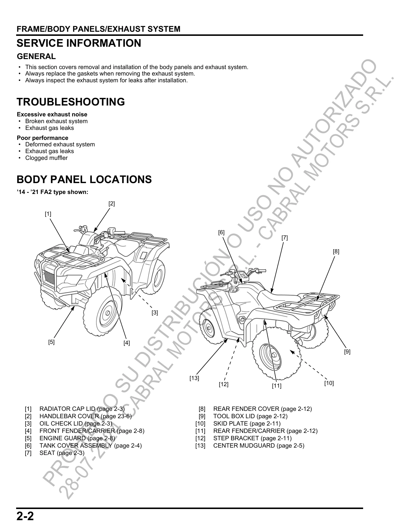
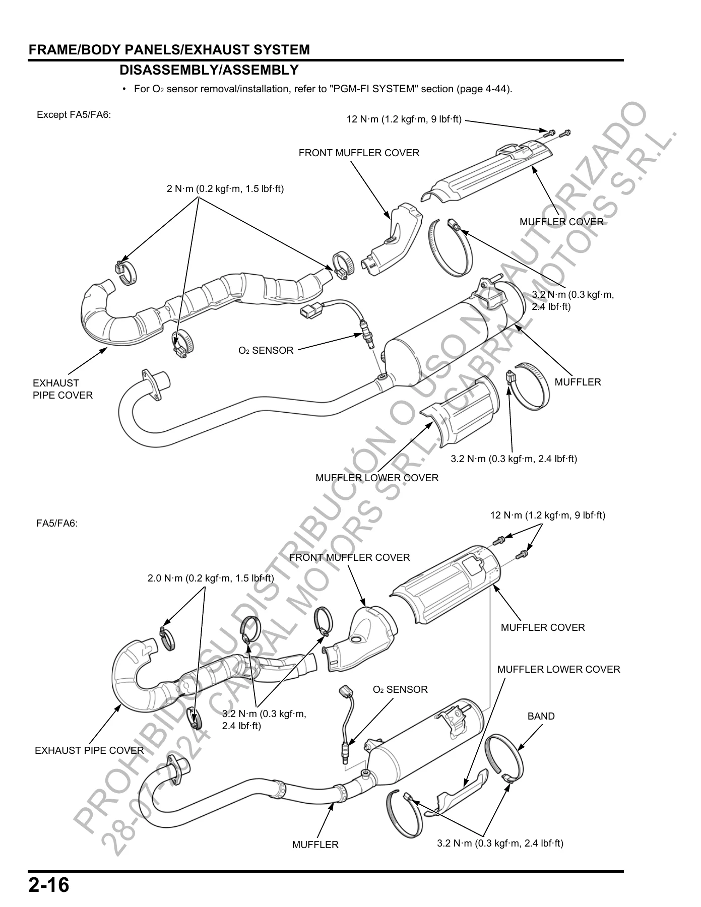
- 2. Frame/Body Panels/Exhaust System – Body Panel Locations; Seat; Tank Cover Assembly; Center Mudguard; Front Fender/Carrier; Rear Fender/Carrier; Exhaust System.
- 3. Maintenance – Maintenance Minder Indicator; Maintenance Schedule; Fuel Line; Throttle Operation; Air Cleaner; Spark Plug; Valve Clearance; Engine Oil and Oil Filter; Radiator Coolant; Final Gear Oil; Brake System; Suspension; Wheels/Tires; Steering System.
- 4. PGM-FI System – Component Location; System Diagram; Troubleshooting Information; Symptom Troubleshooting; DTC Index; DTC Troubleshooting; Sensor Unit; PCM/ECM; O2 Sensor.
- 5. Ignition System – Troubleshooting; Component Location; System Diagram; Ignition System Inspection; Ignition Coil; Ignition Timing; Condenser.
- 6. Electric Starter – Troubleshooting; Component Location; System Diagram; Starter Motor; Starter Relay Switch; Starter Inhibitor Relay/Starter Relay Switch Diode; In-Gear Start Diode.
- 7. Fuel System – System Components; Fuel Line Troubleshooting; Fuel Line Inspection; Fuel Pump Unit; Fuel Tank; Air Cleaner Housing; Throttle Body; IACV; Fuel Injector; EVAP Purge Control Solenoid Valve/Canister.
- 8. Cooling System – Troubleshooting; System Flow Pattern; System Testing; Coolant Replacement; Thermostat; Radiator/Cooling Fan; Radiator Reserve Tank; Water Pump.
- 9. Lubrication System – Troubleshooting; Lubrication System Diagrams; Oil Pump; Relief Valve; Oil Pressure Check.
- 10. Cylinder Head/Valve – Troubleshooting; System Components; Cylinder Compression; Cylinder Head Cover; Cylinder Head; Camshaft.
- 11. Cylinder/Piston – Troubleshooting; System Components; Cylinder/Piston.
- 12. Clutch/Gearshift Linkage (Except FA models) – Front Crankcase Cover; Centrifugal Clutch; Change Clutch; Gearshift Linkage.
- 13. Dual Clutch Transmission (FA models) – DCT System Overview; Symptom Troubleshooting; Component Location; System Diagram; sensors and switches used by the transmission control system.
- 14. Alternator/Starter Clutch – Troubleshooting; System Components; Recoil Starter; Alternator Stator; Flywheel/Starter Clutch.
- 15. Crankcase/Transmission/Crankshaft/Balancer – Troubleshooting; Crankcase Separation; Transmission; Crankshaft/Balancer; Crankcase Bearing Replacement; Crankcase Assembly.
- 16. Engine Removal/Installation – System Components; Engine Removal; Engine Installation.
- 17. Front Wheel/Suspension/Steering – Handlebar; Throttle Housing; Front Wheel; Tires; Wheel Hub and Knuckle; Suspension Arm; Front Shock Absorber; Steering Shaft; Tie-Rod.
- 18. Rear Wheel/Suspension – Troubleshooting; System Components; Rear Wheel; Rear Shock Absorber; Swingarm; Rear Wheel Hub/Knuckle; Rear Suspension Arm.
- 19. Brake System – Brake Fluid Replacement/Air Bleeding; Brake Pad/Disc; Front Master Cylinder; Front Brake Caliper; Rear Brake Drum/Shoes; Rear Brake Pedal; Rear Brake Caliper; Rear Brake Lever.
- 20. Front Driving Mechanism (Except TM1/TE1 models) – Front Drive Shaft; Front Final Drive Removal; Front Propeller Shaft; Front Final Clutch; Front Final Gear Disassembly/Inspection; bearing replacement; Front Final Gear Assembly; Front Final Drive Installation.
- 21. Rear Driving Mechanism – Rear Axle; Rear Drive Shaft; Rear Final Drive.
- 22. Battery/Charging System – Component Location; System Diagram; Battery; Charging System Inspection; Alternator Charging Coil; Regulator/Rectifier; Main Power Relay.
- 23. Lights/Meters/Switches – Headlight; Brake/Taillight; Combination Meter/Indicator; Ignition Switch; Handlebar Switch; Gear Position Switch; Brake Switches; Cooling Fan; Level Sensor; 4WD Select Switch/4WD Indicator.
- 24. Electric Shift Program (ESP: TE1/FE1 models) – Component Location; System Diagram; Symptom Troubleshooting; DTC Index; DTC Troubleshooting; sensors; Shift Control Motor/Reduction Gears.
- 25. Electric Power Steering (EPS: FM2/FA2/FA6 models) – Component Location; System Diagram; Symptom Troubleshooting; DTC Index; DTC Troubleshooting; EPS Indicator Circuit Inspection; EPS ECU.
- 26. Wiring Diagrams – model-specific wiring diagrams for TRX420 configurations covered by the manual.
Together, these chapters provide a workshop-level path from identification and service specifications through diagnosis, scheduled maintenance and major component repair. The combination of model-specific procedures, service limits, torque values, electrical diagrams, component illustrations and troubleshooting information makes the Honda TRX420 TM1 TE1 FM1 FM2 FE1 FA1 FA2 FA5 FA6 Shop Manual PDF useful for both fault tracing and planned overhaul work.
Repair and Service Reference
Use this manual when you need the documented procedure for work such as valve adjustment, engine oil and filter service, cooling-system repair, fuel-injection diagnosis, starter and charging checks, cylinder and piston service, clutch or transmission work, engine removal, steering and suspension repair, brake service, final-drive work, ESP diagnosis, EPS diagnosis or electrical tracing. Following the specified sequences, measurements, service limits and tightening values helps keep repair work aligned with the procedures published for these TRX420 variants rather than relying on generic ATV information.
Get the Manual Instantly
The Honda TRX420 TM1 TE1 FM1 FM2 FE1 FA1 FA2 FA5 FA6 Shop Manual PDF gives you one comprehensive reference for maintenance, diagnosis, adjustment and repair across the covered TRX420 models. Correct procedures, specifications, service limits, torque values and model-specific diagrams matter when servicing closely related variants that use different transmissions, shift systems, steering equipment, suspension layouts and drive arrangements. After purchase, the manual is delivered instantly as a PDF with no shipping required. Open it on a compatible phone, tablet or computer, keep it available in the workshop, and print the pages you need for the job.
Reviews
There are no reviews yet.