
Honeywell Primus Apex Flight Line Maintenance Manual for Pilatus PC-12/47E NG
Original price was: $39.95.$23.95Current price is: $23.95.
Honeywell flight line maintenance and fault isolation guide for the Primus Apex system on the Pilatus PC-12/47E (PC-12 NG). Covers CMC/Remote Terminal use, data loading, ESD handling, and ATA-sorted ground troubleshooting procedures. Pub. No. 006-10667-0000, 28 Feb 2011.
Description
Honeywell Primus Apex Flight Line Maintenance Manual for Pilatus PC-12/47E NG
This Honeywell Primus Apex Flight Line Maintenance Manual for Pilatus PC-12/47E NG is written for technicians who already work the Honeywell Primus Apex installation and need the CMC interface, Remote Terminal, and ground fault isolation path. Cover titling calls the book a Flight Line Maintenance Manual; running headers also use System Description and Operation Manual. Publication number is 006-10667-0000, Revision 000 dated 28 Feb 2011, printed in the U.S.A. Effectivity is marked ALL. The aircraft named throughout is the Pilatus PC-12/47E; later fault steps also point to the Pilatus PC-12 NG Pilot’s Operating Handbook when powering the airplane.
The stated purpose is routine aircraft diagnostics and troubleshooting through the Central Maintenance Computer. The book itself says it is not a substitute for the Aircraft Maintenance Manual and is for reference only. That limit matters on the ramp: use these CMC and fault tasks with the airframe AMM, not in place of it.
File Details
- Manual type: Flight Line Maintenance Manual (headers also read System Description and Operation Manual)
- Brand / system: Honeywell Primus Apex
- Aircraft: Pilatus PC-12/47E (PC-12 NG references in later procedures)
- Language: English
- Page count: 1398
- File format: PDF
- Publication number: 006-10667-0000
- Revision: 000, 28 Feb 2011
- Effectivity: ALL
What This Manual Is For
Line crews on the PC-12/47E spend most avionics time on Crew Alerting System messages, Flight Deck Effects, and maintenance messages stored in the CMC. The Honeywell Primus Apex Flight Line Maintenance Manual for Pilatus PC-12/47E NG walks that path from PC setup and Remote Terminal menus through active and historical faults, then into ATA-sorted isolation tasks. Aircraft with Build 6 and Build 7 software are called out separately where menu graphics and data-loader install steps differ.
Section 1 is the working map of the Aircraft Diagnostic Maintenance System: CMC Function basics, Loadable Diagnostic Information, Aircraft Condition Monitoring Function, Flight History Database, Remote Terminal and Data Loader behavior, member systems, Modular Avionics Unit layout, and network settings. Section 2 is the bulk of the book — fault isolation Task 00-00-00-810 and the chapter procedures that follow it.
Member Systems and ATA Sorting
Member systems on the PC-12/47E are grouped the way the CMC presents them:
IMAGES PREVIEW
- Chapter 21 Air Conditioning — Cabin Pressure Control System and Environmental Control System
- Chapter 22 Automatic Flight Control System — Autopilot
- Chapter 23 Communications — Radio System and Audio Panel
- Chapter 28 Fuel System — Fuel Computer
- Chapter 31 Indicating and Recording — Modular Avionics Unit IO modules, Monitor Warning System, CMF, NIC modules, AGM modules and display graphics
- Chapter 34 Navigation — Traffic Awareness System, Air Data System, Attitude Heading Reference System, Radar Altimeter, Global Positioning System, Distance Measuring, Terrain Awareness and Warning System
- Chapter 45 Central Maintenance System — Transponder, Aircraft Condition and Monitoring System, Central Maintenance Computer
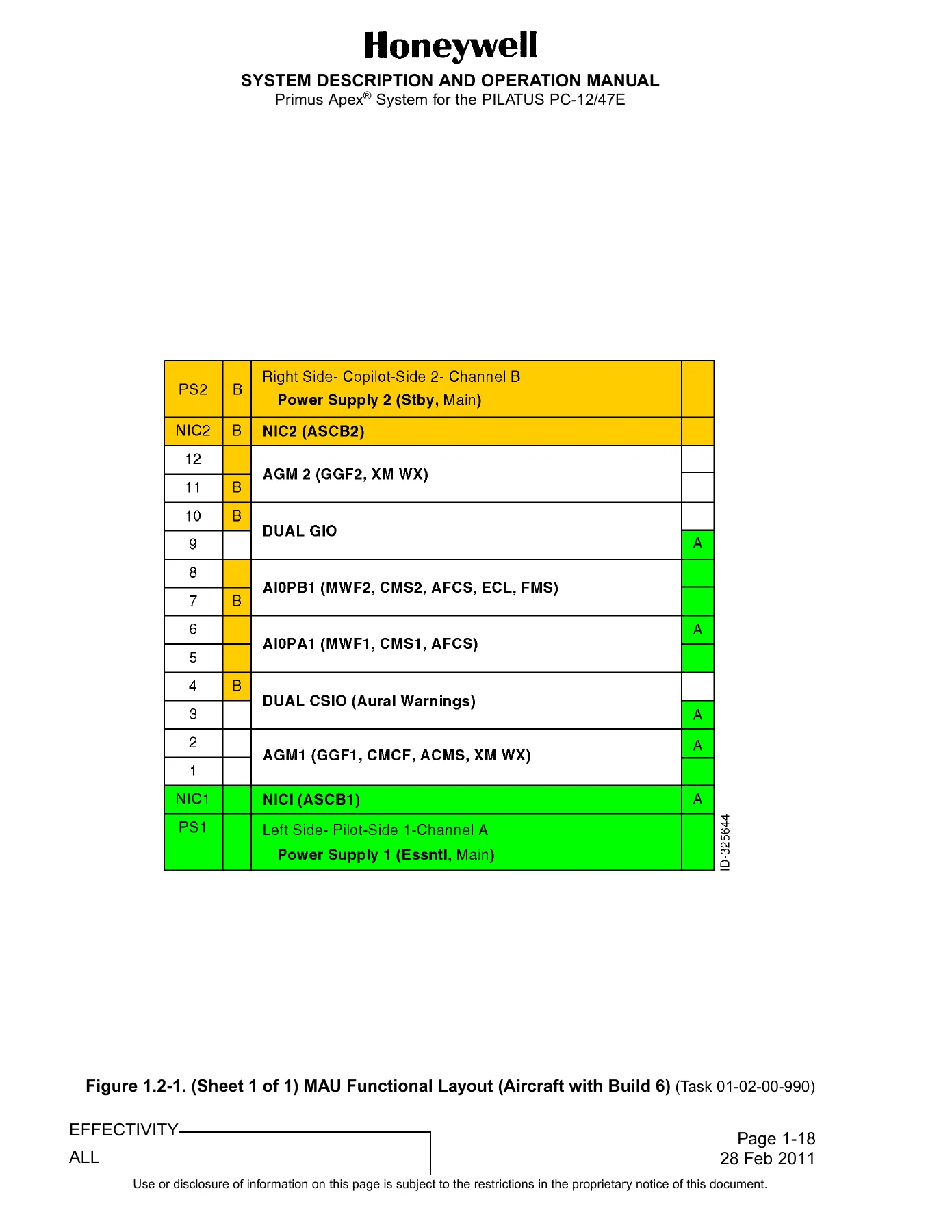
The MAU is described as two channels (A and B) that talk through NIC modules. Dual-channel modules sit on both back-plate channels while the functions they host stay separate. Table 1.2-1 lists module IP addresses used when you ping the LAN from the Remote Terminal: AIOP1A 192.168.1.20, AIOP1B 192.168.33.20, AGM1 192.168.1.17, AGM2 192.168.33.17, CSIO1A 192.168.1.18, CSIO1B 192.168.33.23, GIO1A 192.168.1.23, GIO1B 192.168.33.18, NIC1 192.168.1.1, NIC2 192.168.33.1. Figure 1.2-1 shows the Build 6 MAU slot map (PS1/PS2, NIC1/NIC2, AGM, AIOP, CSIO, GIO).
Chapters Covered
- Introduction — proprietary and export notices, purpose, manual structure, acronyms, electrostatic discharge standard practices
- Section 1 System Overview
- Section 1.1 System Basics — ADMS introduction, CMCF basics, LDI, ACMF, FHDB, CMCF operations, Remote Terminal and Data Loader basics
- Section 1.2 Member Systems — maintenance functions, ATA chapters, MAU
- Section 1.3 Configuring Your PC — hardware requirements, network configuration (10Base2, LTEPIC-25, LANTAP-10, SKU 1001), network settings and IP address, installing RT and DLS for Build 6 and Build 7 aircraft
- Section 1.4 Remote Terminal Basics — navigation, RT menu tree, connection problems, ping command
- Section 1.5 Basic Maintenance and Troubleshooting — system status, active maintenance messages, verifying system configuration
- Section 1.6 Advanced Troubleshooting — repetitive system faults, historical fault reference, time ordered views, downloading log files and erasing memory, diagnostics
- Section 1.7 Data Loading — full load, target load, clearing the Confirm Config CAS message, software loading chart
- Section 2 Fault Procedures — Fault Isolation General (Task 00-00-00-810)
- Section 2.1 Chapter 21 Fault Procedures — ECS temperature sensors and wiring, cabin and underfloor heater switches, A429 faults, pack and duct overtemperature and overpressure, firewall SOV, TCV/FCV EOT, cabin pressure control channels, outflow and safety valves, valve drives
- Section 2.2 Chapter 22 Fault Procedures — AIOP servo power, AIOP watcher and pit trim, ADS and ADAHRS data, yaw and pitch trim command and monitor faults, canard/elevator and aileron servo clutch and motor faults, FMS data, GGF data, PBIT fail and not-run conditions, position-mode faults, and a long run of related AFCS isolation tasks
- Section 2.3 Chapter 23 Fault Procedures — MMDR1 and MMDR2 hardware, fans, COM TX/RX, NAV/LOC, ADF, glideslope, A429 RX, stuck COM mic, reduced power TX
- Section 2.4 Chapter 28 Fault Procedures — fuel quantity probes and wiring, boost pumps, fuel balance, FCMU, LLSC
- Section 2.5 Chapter 31 Fault Procedures — AFCS internal and MWF validity, CMC faults on AIOP channels, CMS, display and IO module paths
- Section 2.6 Chapter 34 Fault Procedures — air data, AHRS, FMS/GPS, traffic, radar altimeter, and related navigation member-system faults
- Section 2.7 Chapter 45 Fault Procedures — CMC, ACMS, GIO, AGM, and central maintenance communication and wiring faults
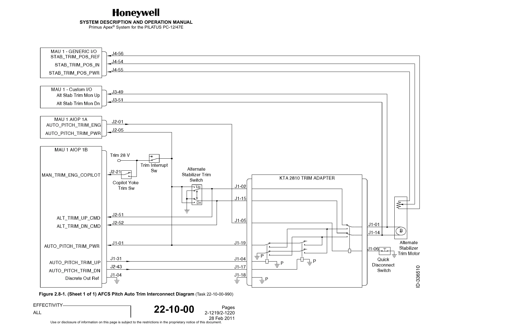
- Section 2.8 Interconnect Diagrams — AFCS Pitch Auto Trim interconnect (Figure 2.8-1) with Honeywell-to-Pilatus connector equivalents referenced from Table 2.0-1
Taken together, the document is a CMC-centered flight-line book: how the diagnostic system is built, how to attach a laptop, how to read status and messages, how to load software, and how to walk each published fault to a yes/no isolation end. Hundreds of individual fault titles sit under the Chapter 21 through Chapter 45 tables; each isolation task generally starts by confirming circuit breakers, powering the airplane per the Pilatus PC-12/47E or PC-12 NG POH, and reading CAS and Flight Deck Effects before the specific troubleshooting tree.
Remote Terminal, PC Setup, and Data Loading
Section 1.3 lists the hardware and LAN pieces used to reach the CMC: 10Base2, LTEPIC-25, LANTAP-10, and SKU 1001, plus the IP configuration steps and the separate RT/DLS install notes for Build 6 versus Build 7 airplanes. Section 1.4 covers menu navigation, the RT tree, failed connections, and the ping command used to prove a module is on the LAN. Typical first checks when a load will not complete include pinging the published module addresses, checking circuit breakers, and confirming the module is seated.
Basic maintenance in Section 1.5 is built around System Status (ATA chapters highlighted when a member system is not operational), Active Maintenance Messages with severity groups matching CAS (Warning, Caution, and related levels), and Configuration screens that show hardware and software identity by ATA chapter. Advanced work in Section 1.6 adds repetitive-fault review, historical search by ATA or by date, time-ordered views, log download and memory erase, and initiated BIT on member systems that support it. Data loading in Section 1.7 splits Full Load and Target Load, includes the procedure to clear the Confirm Config CAS message, and points to the software loading chart that shows what must be loaded on each MAU module.
ESD Handling for MAU Modules
The introduction spends several pages on electrostatic discharge because every MAU module is treated as ESDS. Wrist-strap resistance must measure between 250 kilohms and 1.5 megohms before use. Modules move only in closed Faraday-cage containers, are held by jackscrews or the faceplate frame, and are not placed on unprotected surfaces. Figure 0.0-1 shows the standard ESDS caution symbols used in the book.
How Fault Isolation Is Written
Section 2 opens with general fault isolation, then each ATA chapter begins with a fault table. Individual tasks name the maintenance message or CAS-linked fault, list likely LRUs, and run a branched procedure. Many AFCS and trim tasks send the technician back to the Pilatus PC-12/47E AMM for airframe trim work when the Honeywell path does not clear the fault. Module-failure trees often recycle aircraft power, wait a stated interval (commonly 5, 6, or at least 10 minutes depending on the unit), then decide whether to replace AIOP A, AIOP B, AGM 1, or another named LRU. The AFCS Pitch Auto Trim interconnect at the end of the book is the pictorial reference used by several Chapter 22 trim wiring checks and cites the KTA 2810 trim adapter, MAU AIOP 1A/1B, Custom I/O, and Generic I/O pins.
Practical Use on the Line
Technicians use the Honeywell Primus Apex Flight Line Maintenance Manual for Pilatus PC-12/47E NG when a CAS or maintenance message needs a documented isolation path instead of guesswork across dual-channel MAU hardware. Typical jobs supported by the printed procedures include confirming member-system status after a flight, pulling present-leg versus historical messages, running initiated BIT, loading or targeting software and navigation databases, clearing configuration confirms, pinging a silent AGM or AIOP, and following ECS cabin-pressure, AFCS servo/trim, MMDR radio, fuel-computer, display/IO, navigation, and CMC wiring faults to a replace-or-repair decision. Correct task numbers, wait times, and connector references reduce the chance of swapping the wrong channel module or damaging an ESDS card.
Get the Manual and Start Working
This Honeywell Primus Apex Flight Line Maintenance Manual for Pilatus PC-12/47E NG supports CMC-based diagnostics, Remote Terminal operation, software loading, ESD-safe module handling, and the published ground fault isolation procedures for the Primus Apex installation on the Pilatus PC-12/47E. Using the written isolation trees, IP list, loading chart, and interconnect diagram keeps line work aligned with the same task structure Honeywell printed for this airplane. After payment you receive the PDF immediately — no shipping, readable on any device, and printable for the hangar or the laptop bag. Keep the Pilatus AMM and POH beside it; this book is the CMC and fault-isolation companion, not a replacement for those airframe manuals.
Reviews
There are no reviews yet.