
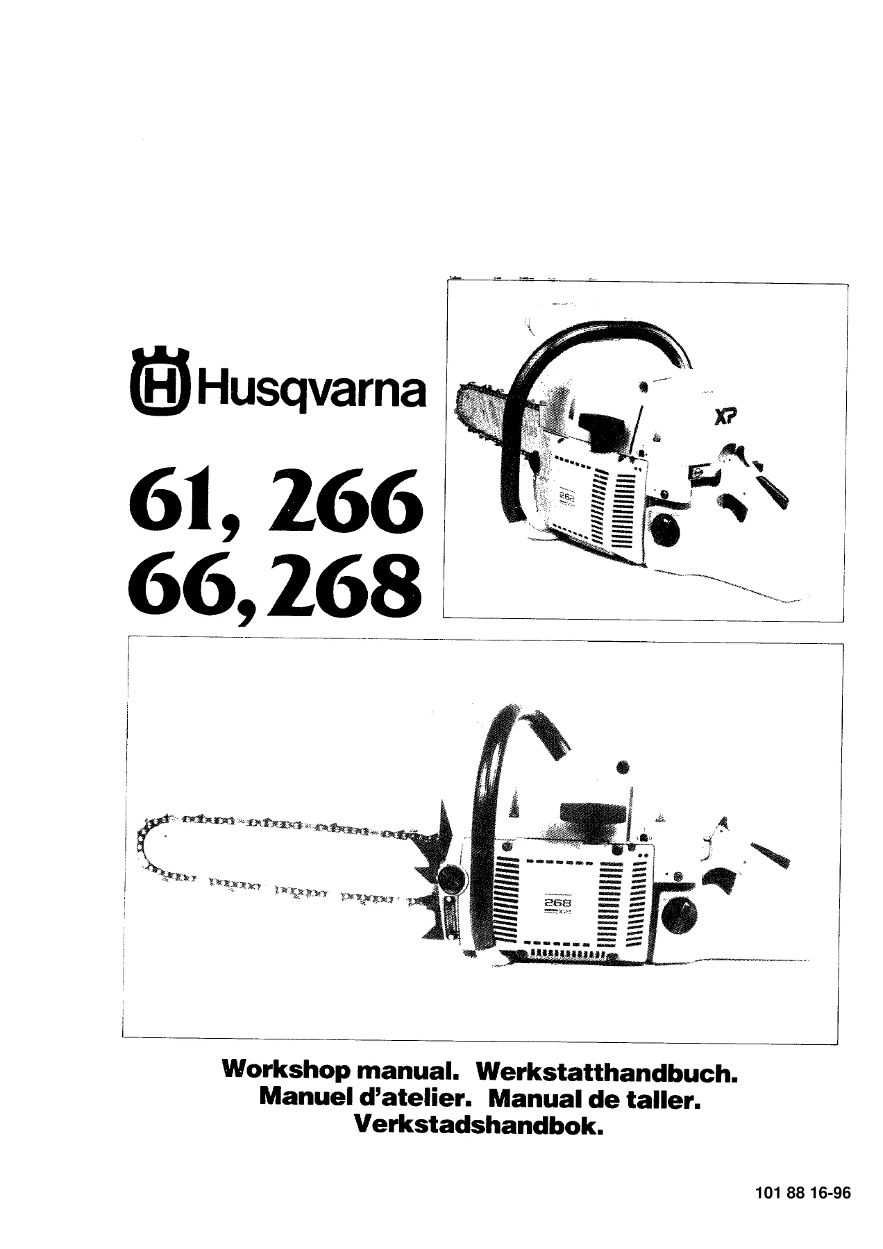
Husqvarna 61 66 266 268 Chainsaw Workshop Manual – Multilingual PDF Repair Guide
Original price was: $49.95.$34.95Current price is: $34.95.
Complete multilingual workshop manual for Husqvarna 61, 66, 266 and 268 chainsaws. Covers engine teardown, ignition, clutch, oil pump, AV system, fuel system, cylinder and crankcase rebuilds with torques, service data and special tool references.
Description
Husqvarna 61, 66, 266 and 268 Chainsaw Workshop Manual
This is the full workshop manual written for the Husqvarna 61, 66, 266 and 268 chainsaws, published under document number 1018816-96. It is a hands-on repair and overhaul guide rather than an owner’s booklet: it walks through stripping, inspecting, measuring, adjusting and reassembling the saw system by system, and it names the special Husqvarna service tools that each job calls for. The manual is presented in five languages side by side — English, German, French, Spanish and Swedish — with every procedure, caption and warning repeated in each language.
File Details
- Manual type: Workshop manual (service and repair)
- Brand: Husqvarna
- Models covered: 61, 66, 266, 268
- Languages: English, German (Werkstatthandbuch), French (Manuel d’atelier), Spanish (Manual de taller), Swedish (Verkstadshandbok)
- Document number: 1018816-96
- Page count: 112
- File format: PDF
Chapters Covered
- 1. Technical specification
- 2. Service Data
- 3. Service tools
- 4. Safety equipment
- 5. Starter device
- 6. Electric system
- 7. Centrifugal clutch
- 8. Lubrication system, Oil pump
- 9. AV-system
- 10. Fuel system
- 11. Cylinder, Piston
- 12. Crankcase, Crankshaft
Technical Specification and Service Data
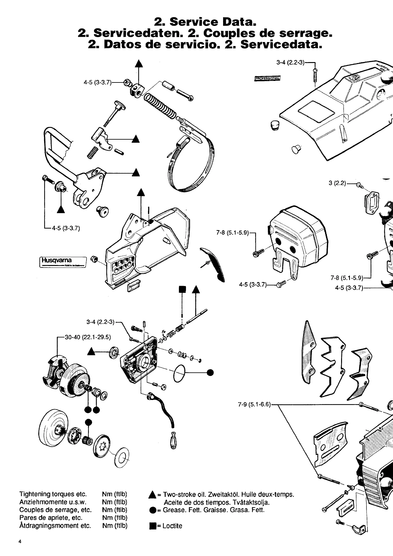
The opening chapters set the baseline numbers you work against. Technical specification breaks out displacement, bore, stroke, maximum power output and speed, idling speed and clutch engagement speed per model, then moves through fuel and oil capacity, oil pump output, oil tank volume, spark plug type, electrode gap, air gap and bar and chain data. Service Data follows with a set of exploded assembly drawings annotated with the tightening torques for the fasteners in each area — handle and hand guard, cylinder cover, clutch cover, crankcase and oil pump among them. Torque figures appear in both Nm and ft/lb, with a legend marking two-stroke oil, grease and Loctite callouts.
Service Tools
A catalogue of the Husqvarna special tools used throughout the book, each with its reference number: pressure gauge, cover plates for intake and exhaust, distance sleeves, piston stop, flywheel puller and holding bar, ball bearing pullers, drift for sealing rings, air gap gauge, tachometer, assembly pliers for the spark plug protector and the centrifugal clutch, and the crankshaft fitting tool set. If a job further on needs a tool, you will find it listed here first.
Safety Equipment — Chain Brake
Full strip and rebuild of the chain brake: removing the adjuster screw and nut, driving out the pivot sleeve halves, removing the brake spring, plastic guide, catch segment and brake band, then reassembling with heat- and cold-resistant lubricant. It gives the wear limit for the band — at least 0.75 mm at the most worn point — and covers the automatic activation check, the release force adjustment against a scale, and the running braking function test. Throttle trigger lockout and chain catcher checks are included as well.
Starter Device
Removal of the starter from the crankcase, unwinding the cord, pulling the starter pulley, replacing the recoil spring and re-tensioning it, fitting a new cord and sealing the knot, and reassembling with the correct preload — the manual notes that with the cord fully out the pulley must still turn at least half a turn before the spring bottoms.
Electric System
This chapter covers the electronic ignition system on these saws, spark plug inspection and gap setting, spark testing, stop switch diagnosis, ignition lead and contact checks, and setting the air gap between the flywheel magnet and the ignition module with the gauge. It explains when to change the ignition module and when the coil also has to go. Heated-handle models get their own section on the generator, the handle switch and resistance testing of the heating coils and handle inserts, including the expected Ohm readings.
Centrifugal Clutch
Clutch removal using the piston stop, spring dismantling with the assembly pliers, and wear limits — at least 1 mm of material remaining on the most worn clutch shoe, and the clutch exchanged as a complete unit to avoid imbalance. Inspection of the clutch centre spokes, the chain sprocket and the drum splines is covered, along with reassembly and greasing the needle bearing through the crankshaft hole.
Lubrication System and Oil Pump
Oil tank draining and cleaning, vent checking, pump removal, and a step-by-step pump teardown covering the clip, washers, spring, plastic washer, adjusting screw and locking screw. It shows how to check the suction channel for dirt by rotating the pump shaft both ways, how to inspect and rotate the wear pin, and how to assemble with the steel washer against the spring and lock the screw with Loctite AA. A troubleshooting table maps insufficient lubrication and leakage against blocked passages, worn pins, damaged hoses and clogged screens.
AV-System
The anti-vibration chapter explains the rubber element layout and the recommended replacement interval, then covers removing the six element screws, separating tank and crankcase, and using the correct fitting tool for each of the three rubber element sizes. The manual is explicit that all rubber elements should be exchanged at the same time.
Fuel System
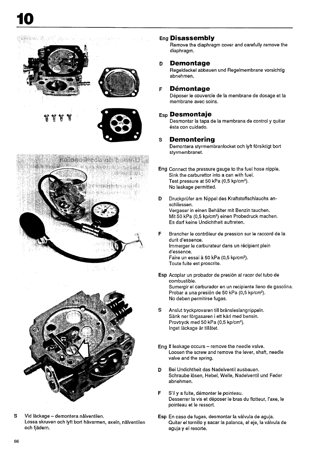
One of the largest chapters. It starts with fuel tank ventilation testing at 50 kPa and the two tank vent types, then moves into carburettor removal for both the 61/66/266 and the 268 layouts. The carburettor itself is broken into pumping, metering and mixing sections, with procedures for pressure testing at 50 kPa, needle valve and lever inspection, pump diaphragm and gasket replacement, fuel screen removal with a needle, welch plug extraction, throttle and choke shaft wear checks, and lever height setting against the carburettor body plane. Final adjustment of the L, H and T needles is given with base settings per model, the full tuning sequence, and the overspeed limits you must not exceed — 12,000 rpm on the 61 and 66, 12,500 rpm on the 266 and 13,300 rpm on the 268. A large fault-finding chart closes the chapter, indexing symptoms from hard starting and flooding through to poor acceleration and four-stroking against the specific causes.
Cylinder, Piston and Silencer
Top-end teardown, carbon removal from the combustion chamber and exhaust port, and a fault-and-remedy table covering broken cooling fins, damaged threads, seizure marks in the cylinder wall, worn surface coating, piston seizure, and rings stuck in their grooves. The remedy side tells you when to grind a light mark out with emery cloth and when the cylinder and piston must be exchanged. Reassembly covers wrist pin and circlip fitting, aligning the piston arrow with the exhaust port, and fitting the cylinder with the rubber seal straddling the crankcase ridge. The silencer section includes the spark arrester screen service note.
Crankcase and Crankshaft
Bar bolt replacement through the oil tank, sealing ring replacement on both the ignition side and the drive side (with the correct mandrels and the 1 mm protrusion above the pump housing face), and complete crankcase splitting with the special tool. It explains heating the crankcase halves to release the ball bearings, checking the crankshaft big-end and small-end for seizure marks and discolouration, and the rule that radial play in the connecting rod means replacement while axial play is acceptable. Reassembly covers pulling the crankshaft into the drive side half, fitting new gaskets and O-rings, tightening screws from the crankshaft outwards, and Loctite on the sealing ring holder screws.
Why This Manual Earns Its Place on the Bench
A saw of this generation does not fail in mysterious ways — it fails at a known wear point, and this manual names those points. With it you can diagnose a flooding carburettor instead of throwing parts at it, set the L and H needles and the idle screw against the factory base settings, test the crankcase and carburettor for leakage at the specified pressures, measure the chain brake band before it becomes a safety problem, and rebuild the top end without guessing which way the piston arrow faces or how much torque the cylinder screws take. The special tool references mean you can either buy or improvise with confidence, because you know exactly what each tool is doing.
IMAGES PREVIEW
Instant PDF Delivery in Five Languages
The file downloads immediately after checkout — no shipping, no waiting, no physical book to keep track of in a workshop. Read it on a laptop, tablet or phone, or print only the pages you need for the job in front of you: the exploded torque views, the carburettor adjustment diagrams and the fault-finding chart are all laid out to be printed and pinned up. Because every procedure is repeated in English, German, French, Spanish and Swedish, the same download works for a mixed-language workshop or a technician who prefers to read the instructions in their first language.
Reviews
There are no reviews yet.