Hyster B199 Service Manual – PDF DOWNLOAD
Original price was: $98.95.$29.95Current price is: $29.95.
Hyster B199 Service Manual – PDF DOWNLOAD
Description
Hyster B199 Service Manual – PDF DOWNLOAD
DESCRIPTION:
Hyster B199 Service Manual – PDF DOWNLOAD
SAFETY PRECAUTIONS MAINTENANCE AND REPAIR :
• When lifting parts or assemblies, make sure all slings, chains, or cables are correctly
fastened, and that the load being lifted is balanced. Make sure the crane, cables, and
chains have the capacity to support the weight of the load.
• Do not lift heavy parts by hand, use a lifting mechanism.
• Wear safety glasses.
• DISCONNECT THE BATTERY CONNECTOR before doing any maintenance or repair
on electric lift trucks. Disconnect the battery ground cable on internal combustion lift
trucks.
• Always use correct blocks to prevent the unit from rolling or falling. See HOW TO PUT
THE LIFT TRUCK ON BLOCKS in the Operating Manual or the Periodic Maintenance
section.
• Keep the unit clean and the working area clean and orderly.
• Use the correct tools for the job.
• Keep the tools clean and in good condition.
• Always use HYSTER APPROVED parts when making repairs. Replacement parts
must meet or exceed the specifications of the original equipment manufacturer.
• Make sure all nuts, bolts, snap rings, and other fastening devices are removed before
using force to remove parts.
• Always fasten a DO NOT OPERATE tag to the controls of the unit whenmaking repairs,
or if the unit needs repairs.
• Be sure to follow the WARNING and CAUTION notes in the instructions.
• Gasoline, Liquid Petroleum Gas (LPG), Compressed Natural Gas (CNG), and Diesel fuel
are flammable. Be sure to follow the necessary safety precautions when handling these
fuels and when working on these fuel systems.
• Batteries generate flammable gas when they are being charged. Keep fire and sparks
away from the area. Make sure the area is well ventilated.
TABLE OF CONTENTS:
Hyster B199 Service Manual – PDF DOWNLOAD
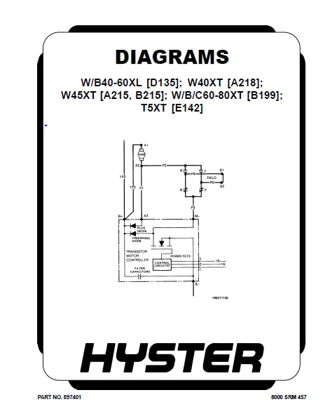
897340-2200SRM0411-(06-2004)-US-EN..............................................  1
	toc.........................................................................  1
		Curtis Transistor Motor Controller......................................  1
		Safety Precautions Maintenance and Repair...............................  2
		General.................................................................  5
		Principles of Operation.................................................  6
			General.............................................................  6
			Transistor Motor Controller.........................................  7
				Basic Controller Operation......................................  9
				Field Effect Transistor (FET)...................................  9
				Motor Circuit That Operates With Pulses.........................  9
				Induction Current From Motor.................................... 11
				Plugging........................................................ 12
				Control Circuit................................................. 13
				Static-Return-To-Off (SRO) Function............................. 13
				Thermal Protection Function..................................... 14
				Low Voltage Protection Function................................. 14
				Current Limit Protection Function............................... 14
				Power Circuit................................................... 14
		Sequence of Operation................................................... 16
			Key Switch.......................................................... 16
			Brake Switch........................................................ 16
			Control Circuit..................................................... 16
			FWD/REV Switch Closed............................................... 16
			Forward Contactor Energized......................................... 16
			Gate Pulse to FETs.................................................. 16
			FETs ON for Time of Gate Pulse...................................... 16
			Gate Pulse Removed.................................................. 16
			Induction Current Flows Through Motor and Flyback Diode............. 24
			Plugging............................................................ 24
		Checks.................................................................. 26
			Checking Contactor Coil............................................. 26
			Checking Transistor Controller...................................... 26
				Checks With Controller Installed................................ 27
				Bench Checks.................................................... 29
				Accelerator Potentiometer Checks and Adjustments................ 30
		Adjustments............................................................. 31
			Plugging Adjustment................................................. 32
			Acceleration Adjustment............................................. 32
			Current Limit Adjustment............................................ 32
		Repairs................................................................. 32
			Contactors.......................................................... 32
				Replace......................................................... 34
			Curtis Contactor Parts, Replace..................................... 34
			GE Contactor Parts, Replace......................................... 34
			Controller, Replace................................................. 36
			Accelerator Potentiometer and Control Switches, Replace and Adju.... 36
		Troubleshooting......................................................... 36
			General............................................................. 36
			General Procedures.................................................. 37
		Fault Procedures........................................................ 37
	tables......................................................................  1
		Table 1. Inductance..................................................... 11
		Table 2. Fault Codes and Display Messages for R30XMS2 Only.............. 43
897401-8000SRM0457-(02-1997)-US................................................. 51
	toc......................................................................... 51
		Diagrams................................................................ 51
		Safety Precautions Maintenance and Repair............................... 52
1490102-8000SRM0923-(11-2004)-US-EN.............................................113
	toc.........................................................................113
		Diagrams................................................................113
		Safety Precautions Maintenance and Repair...............................114
1493912-2200SRM0933-(08-2005)-US-EN.............................................129
	toc.........................................................................129
		Electrical System.......................................................129
		Safety Precautions Maintenance and Repair...............................130
		Major Electrical System Features........................................135
			Integrated System...................................................135
			CAN Bus Advantages..................................................135
			CAN Bus Communications..............................................135
				Electric Steering...............................................135
				Traction........................................................135
				Master Control Unit.............................................135
					Input Devices...............................................135
					Output Devices..............................................136
			Encoder Integrity...................................................136
			Test Encoders.......................................................136
			Proximity Switches..................................................136
			Start Relay.........................................................136
			Battery Discharge Indicator (BDI)...................................136
			Multifunction Display...............................................137
		Setup...................................................................137
			Setup Instructions..................................................137
			General Diagnostics.................................................142
		Power-On Self-Test......................................................143
		SEM Traction Motor Controller...........................................143
			Controller Removal..................................................144
			Install.............................................................144
			Low-Voltage Protection Function.....................................144
			Checking Contactor Coils............................................145
		Checking Transistor Controller..........................................145
			Component Repair and Testing........................................145
			Troubleshooting.....................................................146
			Fault Codes and Display Messages....................................147
		Contactor and Electrical Panel Checks...................................160
			Fuses...............................................................160
			Contactors..........................................................160
				General.........................................................160
				Test............................................................161
				Tips............................................................162
				Disassemble and Assemble........................................162
		Traction Throttle Sensor Removal and Installation.......................163
		Instrument Panel Removal and Installation...............................165
		Key Switch Removal and Installation.....................................165
			Remove..............................................................165
			Install.............................................................165
		Steering Indicator Gauge................................................165
			Test................................................................165
			Remove and Install..................................................165
		Spy Glass Removal and Installation......................................166
		Foot Switch Removal and Installation....................................166
		Slack Chain Switch Removal and Installation.............................167
		Limit Switch Removal and Installation...................................168
		Drive and Hydraulic Pump Motors.........................................168
			Routine Preventive Maintenance......................................168
				Preventive Maintenance Checks...................................169
			Cleanliness.........................................................169
			Connections.........................................................169
			Discoloration and Burn Marks........................................169
			Brushes.............................................................169
			Short in Armature...................................................169
			Commutator..........................................................169
			Bearings............................................................170
		Causes of Motor Failure.................................................170
			Overload............................................................170
			Shock Loading.......................................................170
			Short in Field Coils................................................170
			Short Brushes.......................................................170
			High or Low Commutator Bar..........................................170
			Open Circuit........................................................170
			Low Battery Voltage.................................................170
			Eccentricity of Commutator..........................................170
			Overspeeding........................................................170
		Motor Tests.............................................................171
			Excessive Current Draw..............................................171
			Measuring Current Draw..............................................171
			Excessive Resistance................................................171
			Brush Springs.......................................................171
		Drive Motor.............................................................172
			Inspect.............................................................172
			Preparation of Drive Motor Commutator...............................172
		Fitting Motor Brushes (Motor Removed)...................................173
		Drive Motor Brush and Brush Holder......................................173
			Drive Motor Brush, Remove and Install (Motor Installed).............173
			Drive Motor Brush Holder, Remove and Install (Motor Installed)......173
		Drive Motor Disassembly and Assembly....................................174
		Hoist Pump Motors.......................................................176
			Maintenance Instructions............................................176
			General Information.................................................177
			Brush Replacement...................................................177
			Hoist Motor.........................................................177
				Remove and Install..............................................177
				Disassemble and Assemble........................................177
		Height Encoder Troubleshooting..........................................179
			Description.........................................................179
			Symptoms............................................................179
			24..................................................................179
			Height Encoder Diagnostics..........................................179
			Symptoms and Recommendations........................................179
			Travel Speed Reduction..............................................180
			Additional Encoder Check............................................180
		Steer Encoder Troubleshooting...........................................180
			Description.........................................................180
			MDU Proximity Switch Issues.........................................181
			Steering System Issues..............................................181
			How to Check the Steer Encoder......................................181
	tables......................................................................129
		Table 1. Fault Codes and Display Messages...............................147
		Table 2. Coil Resistance................................................161
Unlock-897060-1900SRM0278-(10-2000)-US..........................................185
Unlock-897618-2200SRM0554-(08-1999)-US..........................................199
Unlock-2033478-8000SRM0686-(12-1999)-US.........................................223
HYSTER B199 SERVICE MANUAL – PDF DOWNLOAD:
IMAGES PREVIEW OF THE MANUAL:
PLEASE NOTE:
- This is the same manual used by the DEALERSHIPS to SERVICE your vehicle.
- The manual can be all yours – Once payment is complete, you will be taken to the download page from where you can download the manual. All in 2-5 minutes time!!
- Need any other service / repair / parts manual, please feel free to contact us at heydownloadss @gmail.com . We may surprise you with a nice offer
S.V