Hyster G006 (H6.00-7.00xl ) Forklift Parts Manual – PDF DOWNLOAD
Original price was: $45.95.$22.95Current price is: $22.95.
Hyster G006 (H6.00-7.00xl ) Forklift Parts Manual
Description
Hyster G006 (H6.00-7.00xl ) Forklift Parts Manual
FILE DETAILS:
LANGUAGE:ENGLISH
PAGES:412
DOWNLOADABLE:YES
FILE TYPE:PDF
HYSTER G006 (H6.00-7.00XL ) FORKLIFT PARTS MANUAL – PDF DOWNLOAD:
IMAGES PREVIEW OF THE MANUAL:
DESCRIPTION:
Hyster G006 (H6.00-7.00xl ) Forklift Parts Manual
HOW TO USE THE ILLUSTRATED PARTS MANUAL
This parts manual describes and illustrates assemblies, subassemblies, and detail parts needed for service replacement. The different constructions are indicated by keys and footnotes. The callouts correspond to descriptions found on the next page.
HOW TO FIND THE DESIRED PART NUMBER
WHEN THE PART NUMBER AND THE NEXT HIGHER ASSEMBLY IS NOT KNOWN:
1. Determine the function and application of the part required. Turn to the Sections Page. Choose the general area of reference most likely to include the part.
2. Turn to the section you chose. Use the Section Table of Contents to determine the assembly which would normally contain the part required. Then locate the part on the assembly breakdown page. WHEN THE PART NUMBER IS NOT KNOWN AND THE NEXT HIGHER ASSEMBLY IS KNOWN:
3. Determine the assembly the required part is used on. Turn to the Table of Contents on Page i.
4. Locate the assembly the required part is used on and turn to the page indicated for that assembly. Then locate the part on the assembly breakdown page.
WHEN THE PART NUMBER IS KNOWN:
5. Use the Numerical Index on Page 12-1 to find thepart number. Turn to the page listed and locate the part as indicated by the item number.
GENERAL:
The assembly breakdowns include part numbers,descriptions, quantities required, keys and footnotes to help in selecting correct parts.
6. Five periods in the PART NO. column (. . . . .)indicate that the part is either Not Serviced Separately or there is a reference to another figure. A figure reference is denoted by a pointing hand
followed by a figure number in the DESCRIPTION column (☞Figure 10)
7. Keys are used to show two or more similar assemblies, RH and LH assembly parts, etc. Select the appropriate key, “A”, “B”, “C”, “D”, or “E” and the corresponding quantity column to find the
required parts. Two periods in the QTY column (..) indicate that the part is not used for that assembly.
8. Indented descriptions under the DESCRIPTION column are used to indicate assemblies and subparts of assemblies. In the example on the previous page, BEARING CAP (Item 2) is a
subpart of the major assembly CASE.
9. Quantities shown are for one assembly. The quantities of the subpart BEARING CAP are indicated as two and two. This means two per CASE assembly.
10. Serial number breaks identify the most current parts information and are shown as follows: ⇒ S/N D001H-2628 Indicates last serial number affected. S/N D001H-2629 ⇒ Indicates the first serial number affected. S/N D001H-1553 ⇔ S/N D001H-3291 Indicates a range of serial numbers affected.
TABLE OF CONTENTS:
Hyster G006 (H6.00-7.00xl ) Forklift Parts Manual
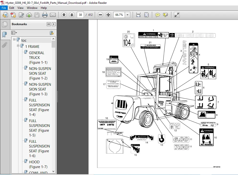
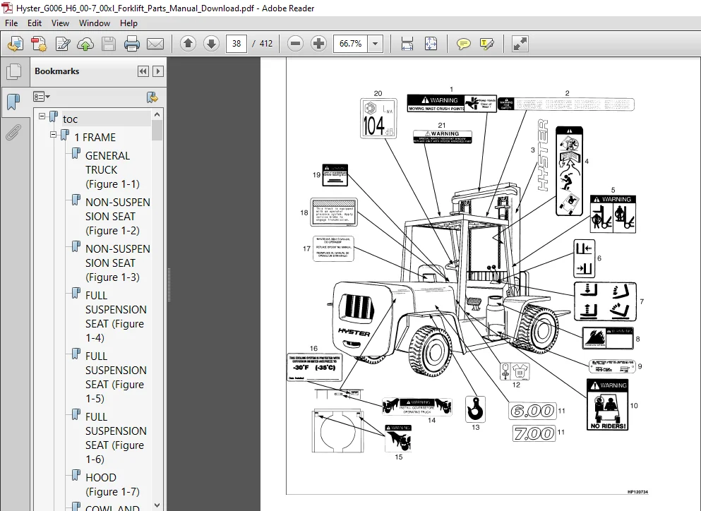
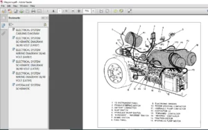
toc..................................................................  1
	1 FRAME.......................................................... 19
		GENERAL TRUCK (Figure 1-1)................................... 22
		NON-SUSPENSION SEAT (Figure 1-2)............................. 24
		NON-SUSPENSION SEAT (Figure 1-3)............................. 26
		FULL SUSPENSION SEAT (Figure 1-4)............................ 28
		FULL SUSPENSION SEAT (Figure 1-5)............................ 30
		FULL SUSPENSION SEAT (Figure 1-6)............................ 32
		HOOD (Figure 1-7)............................................ 34
		COWL AND FLOOR PLATES (Figure 1-8)........................... 36
		LABELS (Figure 1-9).......................................... 38
		OVERHEAD GUARD (Figure 1-10)................................. 40
		COUNTERWEIGHT (Figure 1-11).................................. 42
		LOAD BACKREST EXTENSION (Figure 1-12)........................ 44
		FORKS (Figure 1-13).......................................... 46
	2 ENGINES........................................................ 49
		ENGINE MOUNTING (Figure 2-1)................................. 54
		FLYWHEEL (Figure 2-2)........................................ 56
		EXHAUST (Figure 2-3)......................................... 58
		EXHAUST (Figure 2-4)......................................... 60
		EXHAUST (Figure 2-5)......................................... 62
		EXHAUST (Figure 2-6)......................................... 64
		RADIATOR (Figure 2-7)........................................ 66
		FAN DRIVE AND ALTERNATOR MOUNTING (Figure 2-8)............... 68
		COOLING AND FAN DRIVE (Figure 2-9)........................... 70
		ENGINE ASSEMBLY (Figure 2-10)................................ 72
		COIL ASSEMBLY (Figure 2-11).................................. 74
		CYLINDER BLOCK (Figure 2-12)................................. 76
		CYLINDER HEAD (Figure 2-13).................................. 78
		VALVE COVER AND INLET MANIFOLD (Figure 2-14)................. 80
		CAMSHAFT AND OIL SUMP (Figure 2-15).......................... 84
		OIL PUMP (Figure 2-16)....................................... 88
		EXHAUST MANIFOLD (Figure 2-17)............................... 90
		CYLINDER BLOCK (Figure 2-18)................................. 92
		CYLINDER HEAD AND INDUCTION MANIFOLD (Figure 2-19)........... 94
		VALVE COVER AND ROCKER ARM SHAFT (Figure 2-20)............... 96
		CRANKSHAFT AND PISTONS (Figure 2-21)......................... 98
		OIL PAN AND PUMP (Figure 2-22)...............................100
		WATER PUMP AND OUTLET (Figure 2-23)..........................102
		TIMING GEAR (Figure 2-24)....................................104
		EXHAUST MANIFOLD (Figure 2-25)...............................106
		OIL FILTER (Figure 2-26).....................................107
		OIL COOLER (Figure 2-27).....................................109
		FUEL INJECTION PUMP (Figure 2-28)............................112
		FUEL INJECTION PUMP (Figure 2-29)............................114
		DRIVE ADAPTER (Figure 2-30)..................................116
	3 FUEL SYSTEM....................................................119
		AIR FILTER (Figure 3-1)......................................122
		AIR FILTER (Figure 3-2)......................................124
		AIR FILTER (Figure 3-3)......................................126
		FUEL SUPPLY SYSTEM (Figure 3-4)..............................128
		ENGINE FUEL SYSTEM (Figure 3-5)..............................130
		THROTTLE BODY AND LPG MIXER (Figure 3-6).....................132
		LPG REGULATOR (Figure 3-7)...................................134
		FUEL SUPPLY SYSTEM (Figure 3-8)..............................136
		FUEL SUPPLY SYSTEM (Figure 3-9)..............................138
		FUEL SUPPLY SYSTEM (Figure 3-10).............................140
		WATER SEPARATOR (Figure 3-11)................................142
		FUEL FILTER (Figure 3-12)....................................143
		THROTTLE LINKAGE (Figure 3-13)...............................144
		ACCELERATOR PEDAL AND BRACKET (Figure 3-14)..................146
		ACCELERATOR PEDAL AND BRACKET (Figure 3-15)..................148
		MONOTROL PEDAL (Figure 3-16).................................150
	4 ELECTRICAL SYSTEM..............................................153
		ELECTRICAL SYSTEM (Figure 4-1)...............................156
		DISTRIBUTOR (Figure 4-2).....................................159
		BATTERY DISCONNECT (Figure 4-3)..............................160
		ELECTRICAL SYSTEM (Figure 4-4)...............................162
		BATTERY DISCONNECT (Figure 4-5)..............................166
		INSTRUMENT PANEL (Figure 4-6)................................168
		GAUGE CLUSTER (Figure 4-7)...................................172
		STARTER (Figure 4-8).........................................174
		STARTER MOTOR (Figure 4-9)...................................176
		ALTERNATOR AND MOUNTING (Figure 4-10)........................178
		WIRE HARNESS (Figure 4-11)...................................180
		WIRE HARNESS (Figure 4-12)...................................182
		WIRE HARNESS (Figure 4-13)...................................186
		WIRE HARNESS (Figure 4-14)...................................190
		WIRE HARNESS (Figure 4-15)...................................194
		WIRE HARNESS (Figure 4-16)...................................196
		WIRE HARNESS (Figure 4-17)...................................198
		WIRE HARNESS (Figure 4-18)...................................200
		WIRE HARNESS (Figure 4-19)...................................202
		WIRE HARNESS (Figure 4-20)...................................204
		WIRE HARNESS (Figure 4-21)...................................206
		WIRE HARNESS (Figure 4-22)...................................208
	5 TRANSMISSION...................................................211
		TRANSMISSION (Figure 5-1)....................................214
		TRANSMISSION GEARS (Figure 5-2)..............................218
		TRANSMISSION CONTROL VALVE (Figure 5-3)......................220
		TRANSMISSION CONTROL LINKAGE (Figure 5-4)....................224
		TRANSMISSION CONTROL LINKAGE (Figure 5-5)....................228
		CLUTCH PACK (Figure 5-6).....................................230
		CLUTCH PACK (Figure 5-7).....................................232
		CLUTCH PACK (Figure 5-8).....................................234
		CLUTCH PACK (Figure 5-9).....................................236
		TORQUE CONVERTER (Figure 5-10)...............................238
		DRIVE SHAFT ASSEMBLY (Figure 5-11)...........................240
		DRIVE AXLE (Figure 5-12).....................................242
		DIFFERENTIAL AND CARRIER (Figure 5-13).......................244
		AXLE HOUSING AND ATTACHING PARTS (Figure 5-14)...............247
	6 STEERING SYSTEM................................................249
		STEERING COLUMN (Figure 6-1).................................252
		STEERING CONTROL UNIT (Figure 6-2)...........................254
		STEERING PUMP (Figure 6-3)...................................256
		STEERING AXLE (Figure 6-4)...................................258
		STEERING CYLINDER (Figure 6-5)...............................262
		STEERING CYLINDER (Figure 6-6)...............................264
	7 BRAKE SYSTEM...................................................265
		PARK BRAKE (Figure 7-1)......................................268
		BRAKE LINES (Figure 7-2).....................................270
		BRAKE LINES (Figure 7-3).....................................272
		BRAKE PEDAL LINKAGE (Figure 7-4).............................274
		BRAKE (Figure 7-5)...........................................278
		BRAKE BOOSTER (Figure 7-6)...................................280
		MASTER CYLINDER (Figure 7-7).................................282
	8 HYDRAULIC SYSTEM...............................................285
		HYDRAULIC SYSTEM (Figure 8-1)................................288
		DRIVE SHAFT (Figure 8-2).....................................290
		STEERING HYDRAULIC (Figure 8-3)..............................292
		HYDRAULIC PUMP (Figure 8-4)..................................296
		HYDRAULIC TANK (Figure 8-5)..................................298
		HYDRAULIC OIL FILTER (Figure 8-6)............................300
		TILT CYLINDER (Figure 8-7)...................................302
		CONTROL VALVE (Figure 8-8)...................................304
		CONTROL VALVE ATTACHING PARTS WITH FITTINGS (Figure 8-9).....306
		CONTROL VALVE (Figure 8-10)..................................310
		CONTROL VALVE ATTACHING PARTS WITH FITTINGS (Figure 8-11)....312
		CONTROL VALVE ATTACHING TUBES (Figure 8-12)..................314
		TRANSMISSION COOLING (Figure 8-13)...........................316
	9 MAST-TWO STAGE LIMITED FREE-LIFT...............................319
		OUTER MAST (Figure 9-1)......................................322
		INNER MAST (Figure 9-2)......................................324
		LIFT (Figure 9-3)............................................326
		LIFT CYLINDER (Figure 9-4)...................................328
		CARRIAGE (Figure 9-5)........................................330
		HEADER HOSE (Figure 9-6).....................................332
	10 MAST-THREE STAGE FULL FREE-LIFT...............................335
		OUTER MAST (Figure 10-1).....................................338
		INTERMEDIATE MAST (Figure 10-2)..............................340
		INNER MAST (Figure 10-3).....................................342
		MAIN LIFT (Figure 10-4)......................................344
		FREE-LIFT (Figure 10-5)......................................346
		LIFT CYLINDER (Figure 10-6)..................................348
		LIFT CYLINDER (Figure 10-7)..................................350
		CARRIAGE (Figure 10-8).......................................352
		HEADER HOSE (Figure 10-9)....................................354
	11 OPTIONS.......................................................357
		CAB (Figure 11-1)............................................360
		HEATER (Figure 11-2).........................................364
		WIPER AND FAN (Figure 11-3)..................................366
		SIDE-SHIFT CARRIAGE (Figure 11-4)............................368
		SIDE-SHIFT CARRIAGE (Figure 11-5)............................370
		SIDE-SHIFT CYLINDER (Figure 11-6)............................374
		LIGHTS (Figure 11-7).........................................376
		ROTATING BEACON (Figure 11-8)................................380
		TIRES AND WHEELS (Figure 11-9)...............................382
		TIRES AND WHEELS (Figure 11-10)..............................384
PLEASE NOTE:
- This is the SAME manual used by the dealers to troubleshoot any faults in your vehicle. This can be yours in 2 minutes after the payment is made.
- Contact us at [email protected] should you have any queries before your purchase or that you need any other service / repair / parts operators manual.


Justin Spencer –