Trusted Business
Verified & Licensed
Virus Free Files
100% Safe Downloads
Secure Payment
SSL Protected
Instant Delivery
Available Immediately
Sale!
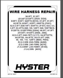
Hyster C098 (E70-120XL) Service Manual – PDF DOWNLOAD
Original price was: $98.95.$31.95Current price is: $31.95.
Hyster C098 (E70-120XL) Service Manual – PDF DOWNLOAD
Instant PDF Download
Available immediately
Save to Your Device
Download & keep forever
Antivirus Scanned
100% virus-free
Trusted Worldwide
175,000+ customers
Description
Hyster C098 (E70-120XL) Service Manual – PDF DOWNLOAD
FILE DETAILS:
Hyster C098 (E70-120XL) Service Manual – PDF DOWNLOAD
Language : English
Pages : 805
Downloadable : Yes
File Type : PDF
Size: 20.9 MB
TABLE OF CONTENTS:
Hyster C098 (E70-120XL) Service Manual – PDF DOWNLOAD
Battery Discharge Indicators....................................................................................................................  1
	INTRODUCTION................................................................................................................................  1
		GENERAL.................................................................................................................................  1
		INDICATORS WITH METER MOVEMENTS.........................................................................................................  2
		BATTERY INDICATORS WITH LCD OR LED DISPLAYS.............................................................................................  3
			Liquid Crystal Displays.............................................................................................................  3
			Light Emitting Diode Displays.......................................................................................................  7
	CHECKS AND ADJUSTMENTS......................................................................................................................  9
		BATTERY INDICATORS WITHOUT LIFT INTERRUPT, EARLY MODELS.................................................................................  9
		BATTERY INDICATORS WITH LIFT INTERRUPT, EARLY MODELS....................................................................................  9
			Reset Potentiometer.................................................................................................................  9
			Specific Gravity Alarm.............................................................................................................. 10
		BATTERY INDICATORS WITHOUT LIFT INTERRUPT, LATER MODELS................................................................................. 11
		BATTERY INDICATORS WITH LIFT INTERRUPT, EARLY MODELS.................................................................................... 11
			Reset Potentiometer................................................................................................................. 11
			Discharge Potentiometer............................................................................................................. 11
		LED DISPLAY WITH LIFT INTERRUPT......................................................................................................... 12
		CHECKING CURTIS 933-1 METER............................................................................................................. 12
			Reset Check......................................................................................................................... 12
			Discharge Check..................................................................................................................... 13
			Lockout Check....................................................................................................................... 13
			LED's Do Not Illuminate............................................................................................................. 14
			Hourmeter Check..................................................................................................................... 14
			Hour Glass Icon..................................................................................................................... 14
			ADJUSTMENT OF CURTIS 933-1 METER.................................................................................................... 14
			CHECKING CURTIS 1215 BATTERY INDICATOR.............................................................................................. 14
			ADJUSTING CURTIS 1215 BATTERY INDICATOR............................................................................................. 15
				Voltage Selection............................................................................................................... 16
			ADJUSTING BDI OF SEM DISPLAY PANEL.................................................................................................. 17
		REPAIRS................................................................................................................................. 17
			BATTERY INDICATORS.................................................................................................................. 17
				Replacement..................................................................................................................... 17
			CONTROLLER FOR THE BATTERY INDICATOR................................................................................................ 17
				Replacement..................................................................................................................... 17
			DISPLAY PANEL COMPONENTS............................................................................................................ 17
			REPLACING SEM DISPLAY PANEL......................................................................................................... 17
			SEM Display Panel REMOVAL........................................................................................................... 19
				Removal And Replacement......................................................................................................... 19
Brake System.................................................................................................................................... 21
	BRAKE SYSTEM................................................................................................................................ 21
		GENERAL................................................................................................................................. 21
		DESCRIPTION AND OPERATION............................................................................................................... 21
		BRAKE BOOSTER AND MASTER CYLINDER....................................................................................................... 21
		MASTER CYLINDER......................................................................................................................... 21
		BRAKE SERVICE ASSEMBLY.................................................................................................................. 23
		PARKING BRAKE........................................................................................................................... 24
	REPAIRS..................................................................................................................................... 24
		BRAKE SHOE ASSEMBLIES................................................................................................................... 24
			Removal and Disassembly............................................................................................................. 24
			Cleaning and Inspection............................................................................................................. 25
			Assembly and Installation........................................................................................................... 27
		MASTER CYLINDER, S3.50-5.50XL (S70-120XL) and H3.50-5.00XL (H70-110XL).................................................................. 30
			Removal............................................................................................................................. 30
			Disassembly......................................................................................................................... 30
			Assembly............................................................................................................................ 31
			Installation........................................................................................................................ 31
		MASTER CYLINDER, E3.50-5.50L (E70-120XL, E70-120XL3).................................................................................... 31
			Removal and Disassembly............................................................................................................. 31
			Cleaning and Inspection............................................................................................................. 32
			Assembly and Installation........................................................................................................... 32
		BRAKE BOOSTER........................................................................................................................... 32
			Removal............................................................................................................................. 32
			Disassembly......................................................................................................................... 32
			Cleaning and Inspection............................................................................................................. 33
			Assembly............................................................................................................................ 33
			Installation........................................................................................................................ 34
	CHECKS AND ADJUSTMENTS...................................................................................................................... 34
		REMOVE THE AIR FROM THE BRAKE SYSTEM.................................................................................................... 34
		ADJUST THE BRAKE PEDAL, H3.50-5.00XL (H70-110XL) With Manual Transmission and E3.50-5.50 (E70-120XL, E70-120XL3)........................ 34
		ADJUST THE BRAKE SHOES.................................................................................................................. 36
		ADJUST THE PARKING BRAKE, S3.50-5.50XL (S70-120XL) H3.50-5.00XL (H70-110XL)............................................................. 37
		ADJUST THE PARKING BRAKE LEVER AND SWITCH, E3.50-5.50XL (E70-120XL, E70-120XL3)......................................................... 37
		CHECK THE RELIEF VALVE ON THE BRAKE BOOSTER............................................................................................. 37
	TROUBLESHOOTING............................................................................................................................. 38
Capacities & Specification...................................................................................................................... 40
DC Motor Maintenance............................................................................................................................ 49
	INTRODUCTION................................................................................................................................ 49
		ELECTRIC MOTOR MAINTENANCE, GENERAL..................................................................................................... 49
		BRUSH AND COMMUNICATOR INSPECTION....................................................................................................... 49
			Hydraulic Pump Motor And Traction Motor............................................................................................. 49
			Steering Pump Motor................................................................................................................. 51
	BRUSH WEAR REPLACEMENT GUIDE................................................................................................................ 51
		Commutator Problems..................................................................................................................... 53
		BRUSH REPLACEMENTS...................................................................................................................... 55
		DISASSEMBLY OF MOTORS................................................................................................................... 57
			Traction Motor And Hydraulic Pump Motor............................................................................................. 57
			Steering Pump Motor................................................................................................................. 63
		ASSEMBLY OF MOTORS...................................................................................................................... 65
			Traction Motor And Hydraulic Pump Motor ............................................................................................ 65
			Steering Pump Motor................................................................................................................. 65
		BRUSH ALIGNMENT, TRACTION AND HYDRAULIC MOTORS.......................................................................................... 65
		TESTS FOR A DAMAGED FIELD AND ARMATURE.................................................................................................. 66
			Test For An Open Circuit In The Armature............................................................................................ 66
			Test For A Short-Circuit In One Armature Winding.................................................................................... 66
			Test For A Short-Circuit To Armature Shaft.......................................................................................... 67
			Test For An Open Circuit In A Field Coil............................................................................................ 67
			Test For A Short-Circuit In A Field Coil............................................................................................ 67
			Test For A Short-Circuit Between The Field And The Motor Case....................................................................... 68
			Brush Holder Test................................................................................................................... 68
	TROUBLESHOOTING............................................................................................................................. 68
Diagrams EV-100-200 Motor Controller............................................................................................................ 70
	FIGURE 1. SCHEMATIC DIAGRAM, EV–100 OR EV–200 SCR TRACTION MOTOR CONTROL, 36–48 VOLTS....................................................... 71
	FIGURE 2. WIRING DIAGRAM, EV–100 SCR TRACTION MOTOR CONTROL WITH SINGLE OR DUAL HYDRAULIC PUMP MOTOR CONTACTOR CONTROL...................... 73
	FIGURE 3. WIRING DIAGRAM, EV–200 SCR TRACTION MOTOR CONTROL WITH EV–100 SCR HYDRAULIC PUMP MOTOR CONTROL.................................... 75
	FIGURE 4. WIRING DIAGRAM, CONTROL SWITCHES.................................................................................................. 77
	FIGURE 5. HYDRAULIC PUMP MOTOR CONTROLS (1 OF 3)............................................................................................ 79
	FIGURE 6. BATTERY INDICATORS................................................................................................................ 84
	FIGURE 7. HYDRAULIC SCHEMATIC............................................................................................................... 85
	FIGURE 8. SCHEMATIC AND WIRING DIAGRAM – 12V LIGHTS......................................................................................... 87
Diagrams EV-100-200LX Motor Controller.......................................................................................................... 88
	FIGURE 1. SCHEMATIC DIAGRAM, EV-100 OR EV-200 SCR TRACTION MOTOR CONTROL, 36-48 VOLTS....................................................... 89
	FIGURE 2. WIRING DIAGRAM, EV-100 SCR TRACTION MOTOR CONTROL WITH SINGLE OR DUAL HYDRAULIC PUMP MOTOR CONTACTOR CONTROL...................... 91
	FIGURE 3. WIRING DIAGRAM, EV-200 SCR TRACTION MOTOR CONTROL WITH EV-100 SCR HYDRAULIC PUMP MOTOR CONTROL.................................... 93
	FIGURE 4. WIRING DIAGRAM, CONTROL SWITCHES (1 OF 2)......................................................................................... 95
	FIGURE 5. HYDRAULIC PUMP MOTOR CONTROLS (1 OF 4)............................................................................................ 99
	FIGURE 6. EV-100 "LX" SERIES GE OR ITW DISPLAY WITH LIFT INTERRUPT - WITHOUT PUMP MOTOR SCR CONTROL SCHEMATIC...............................106
	FIGURE 7. BATTERY INDICATORS................................................................................................................107
Diagrams EV-100ZX Motor Controller..............................................................................................................108
	FIGURE 1. HYDRAULIC SCHEMATIC...............................................................................................................108
	FIGURE 2. SCHEMATIC DIAGRAM, EV-100ZX OR EV-200ZX SCR MOTOR CONTROLLERS, 36-48 VOLTS........................................................110
	FIGURE 3. WIRING DIAGRAM, EV-100ZX OR EV-200ZX SCR MOTOR CONTROLLERS, 36-48 VOLTS...........................................................116
	FIGURE 4. CABLE DIAGRAM, EV-100ZX OR EV200-ZX SCR MOTOR CONTROLLERS, 36-48 VOLTS............................................................126
	FIGURE 5. DETAIL DIAGRAM, EV-100ZX OR EV-200ZX SCR MOTOR CONTROLLERS, 36-48 VOLTS...........................................................127
	FIGURE 6. CONTROL PANELS, EV100ZX OR EV-200ZX SCR MOTOR CONTROLLERS, 36-48 VOLTS............................................................128
	FIGURE 7. SCHEMATIC AND WIRING DIAGRAM - 12V LIGHTS.........................................................................................130
Drive Axle Speed Reducer & Differential.........................................................................................................131
	DRIVE AXLE..................................................................................................................................131
		GENERAL.................................................................................................................................131
		DESCRIPTION.............................................................................................................................131
	REPAIRS.....................................................................................................................................132
		REMOVAL.................................................................................................................................132
			General.............................................................................................................................132
			Traction Motor, Speed Reducer, and Differential.....................................................................................132
		DISASSEMBLY.............................................................................................................................135
			Speed Reducer.......................................................................................................................135
			Differential........................................................................................................................135
		CLEANING................................................................................................................................135
		INSPECTION..............................................................................................................................135
		ASSEMBLY................................................................................................................................136
			Speed Reducer.......................................................................................................................136
		ADJUSTMENTS OF SHIMS FOR THE PINION ASSEMBLY............................................................................................137
			Differential........................................................................................................................138
		DRIVE AXLE HOUSING......................................................................................................................139
			Removal.............................................................................................................................139
			Cleaning............................................................................................................................141
			Inspection..........................................................................................................................141
			Assembly............................................................................................................................141
	TROUBLESHOOTING.............................................................................................................................144
Electrical System (trucks with controller prior to ZX)..........................................................................................145
	ELECTRICAL CHECKS AND ADJUSTMENTS FOR SitDrive) ELECTRICAL LIFT TRUCKS......................................................................145
		GENERAL.................................................................................................................................145
		CONTROL AND POWER FUSES.................................................................................................................150
		CONTROL CARD ADJUSTMENTS................................................................................................................151
			Adjusting Creep Speed, "CREEP'......................................................................................................153
			Adjusting Controlled Acceleration, "C/A" ...........................................................................................153
			Adjusting Current Limit, "C/L"......................................................................................................154
			Adjust "1A TIME"....................................................................................................................155
			Adjust 1A Drop Out, "1A D.O"........................................................................................................157
			Adjust Plugging, "PLUG".............................................................................................................157
			Ramp Start..........................................................................................................................157
			Adjust Field Weakening Pick Up and Drop Out, "F.W.P.U." And "F.W.D.O."..............................................................157
			Adjust "REGEN C/L" (Current Limit)..................................................................................................158
			Adjust "REGEN D.O." (Drop Out)......................................................................................................158
		PROPORTIONAL CONTROL (J25-35A Only).....................................................................................................161
		SCR CONTROL, DUAL HYDRAULIC PUMP MOTORS.................................................................................................162
		SCR CONTROL, SINGLE PUMP MOTOR..........................................................................................................162
			Accelerator Card (E-20-100B, J40-60AS Only).........................................................................................163
			Circuit Description For Accelerator Card Used With A Seat Switch....................................................................164
			Accelerator "START" (IC3)...........................................................................................................165
			Accelertor "1A TIME" (IC2)..........................................................................................................165
			Circuit Description For Accelerator Card Used With A Seat Brake.....................................................................165
			Accelerator "START" (IC3)...........................................................................................................166
			Accelerator "1A TIME" (IC1 and IC2).................................................................................................166
			CHECK THE ACCELERTOR CARD...........................................................................................................166
			ADJUSTING THE ACCELERATOR CARD......................................................................................................166
		THE POTENTIOMETERS AND CONTOL SWITCHES..................................................................................................166
			Steering Potentiometer (J25-35A Only)...............................................................................................166
			Accelerator Potentiometer And Start Switch (E20-120XL And J25-60XL Only)............................................................168
			Accelerator Potentiometer And Direction Switch......................................................................................169
			Adjusting Start Switch..............................................................................................................170
			"FORWARD" And "REVERSE" Switch (MONOTROL) (Earlier Production Lift Trucks)..........................................................170
			Direction Switches (MONOTROL) (Later Production Lift Trucks)........................................................................171
			"FORWARD" And "REVERSE" Switch (Steering Column)....................................................................................172
			Hydraulic Pump Switch...............................................................................................................172
			Replace The Key Switch..............................................................................................................172
			Adjust The Seat Switch..............................................................................................................172
			Adjust The Brake Switch.............................................................................................................173
			Parking Brake Switch................................................................................................................173
			Rocker Switch.......................................................................................................................174
		HYDRAULIC PUMP SOFT START (E100-120B Only) (72/80 Volt Only)............................................................................175
Electrical System (trucks with ZX controllers)..................................................................................................176
	ELECTRICAL SYSTEM...........................................................................................................................176
		GENERAL.................................................................................................................................176
		"LX" SERIES DISPLAY PANEL...............................................................................................................177
			Hourmeter Functions.................................................................................................................178
			Battery Indicator Function..........................................................................................................178
			Status Code Function................................................................................................................179
		"ZX" SERIES DISPLAY PANELS..............................................................................................................179
			Display Panel.......................................................................................................................179
			Basic Display Panels................................................................................................................179
			Performance Display.................................................................................................................181
			Brush Wear Indicators...............................................................................................................184
		SEM DISPLAY PANELS - FEATURES...........................................................................................................184
			Description Of Common Features......................................................................................................185
			LED SYMBOL INDICATORS...............................................................................................................185
			LCD SCREEN..........................................................................................................................185
			BATTERY DISCHARGE INDICATOR (BDI)...................................................................................................185
			SERVICE REMINDER....................................................................................................................185
			STATUS CODES........................................................................................................................185
			HOURMETER...........................................................................................................................185
			Additional Features Of Premium Display Panel .......................................................................................185
			Descriptions Of Additional Features (Available With The Premium Display) ...........................................................186
			LCD SCREEN..........................................................................................................................186
			OPERATOR PASSWORDS..................................................................................................................186
			DAILY CHECK LIST AND SERVICE ITEMS..................................................................................................186
			PERFORMANCE MODELS..................................................................................................................186
			STATUS CODE LISTS...................................................................................................................186
			ADJUSTMENTS OF BDI..................................................................................................................187
		SEM DISPLAY PANEL INDICATORS............................................................................................................187
			All Indicator Symbols...............................................................................................................187
			Hourmeter Indicator Symbol..........................................................................................................188
			Wrench Indicator Symbol.............................................................................................................188
			Battery Indicator Symbol............................................................................................................188
			Battery State-Of-Charge (BDI).......................................................................................................188
			Brake Fluid Too Low Symbol..........................................................................................................188
			Parking Brake Symbol................................................................................................................188
			Fasten Seat Belt Symbol.............................................................................................................188
			LCD "Screen" (Standard Display Panel)...............................................................................................188
		ADDITIONAL COMPONENTS OF THE PREMIUM DISPLAY PANEL -SEM.................................................................................188
			Alpha Numeric "Screen"..............................................................................................................188
			"Star" Push Button..................................................................................................................189
			Push Buttons #1 Through #5..........................................................................................................189
		OTHER CONTROL COMPONENTS................................................................................................................189
	REPLACEMENT.................................................................................................................................190
		DISPLAY PANEL COMPONENTS - "LX" AND "ZX"................................................................................................190
			Replace The Display Panel Assembly..................................................................................................190
			Replace The Key Switch..............................................................................................................191
			Indicator LEDs......................................................................................................................191
			Battery Indicators..................................................................................................................191
			Digital Display (Performance Display Panel Only) ...................................................................................191
			Status Code Or Performace Level Switches And Indicator LEDs (Performance Display Panel Only)........................................193
			Replace Parts Of The Basic Display Panel ...........................................................................................193
			Replace Parts Of The Performance Display Panel......................................................................................194
		SEM DISPLAY PANEL.......................................................................................................................195
			Removal And Replacement.............................................................................................................195
		REPLACE MOTOR CONTROLLER (SR or SP).....................................................................................................195
		OTHER CONTROL COMPONENTS................................................................................................................195
			Start Swtich........................................................................................................................195
			Brake Light Switch..................................................................................................................196
			Seat Switch.........................................................................................................................197
			Adjust The External Seat Switch.....................................................................................................198
			Switch For Optional Seat Brake......................................................................................................198
			Parking Brake Switch................................................................................................................198
			Direction Switches  (Monotrol Pedal)................................................................................................199
			Direction Control Switches (Steering Column)........................................................................................200
			Direction Control Switches, E70-120XL3 (Steering Column)............................................................................201
			Brake Fluid Switch..................................................................................................................201
			Brush Wear And Over Temperature Sensors.............................................................................................201
			Rocker Switches For Lights .........................................................................................................202
			Accelerator Position Sensor.........................................................................................................202
			On-Demand Steering Components.......................................................................................................204
			Lights, Converter, Relay And Reverse Alarm..........................................................................................206
			Horn And Horn Buttons...............................................................................................................209
			Hydraulic Pump Switches.............................................................................................................210
	CHECKS AND ADJUSTMENTS......................................................................................................................210
		GENERAL.................................................................................................................................210
		CONTROL AND POWER FUSES - "LX" OR "ZX"..................................................................................................210
		CONTROL AND POWER FUSES - SEM...........................................................................................................213
		CHECK BRUSH WEAR AND OVER TEMPERATURE SENSORS - "LX" OR "ZX"............................................................................216
		THERMAL SENSORS - SEM...................................................................................................................216
		ADJUST THE START SWITCH.................................................................................................................216
			Accelerator Potentiometer And Start Switch, E20-120XL, E70-120XL3...................................................................217
			Direction Switches (MONOTROL).......................................................................................................219
			ADJUST THE BRAKE LIGHT SWITCH.......................................................................................................219
			CHECK SEAT SWITCH...................................................................................................................219
			ADJUST THE SWITCH FOR OPTIONAL SEAT BRAKE...........................................................................................219
			ADJUST THE PARKING BRAKE SWITCH.....................................................................................................220
			DIRECTIONAL SWITCHES................................................................................................................220
			DIRECTIONAL SWITCHES (STEERING COLUMN)..............................................................................................220
			HYDRAULIC PUMP SWITCHES.............................................................................................................220
			MONOTROL PEDAL OR ACCELERATOR PEDAL ADJUSTMENT......................................................................................220
			ADJUST THE ACCELERATOR POSITION SENSOR..............................................................................................221
EV-100 Motor Controller Description & Operation.................................................................................................223
	EV-100E MOTOR CONTROLLER, DESCRIPTION AND OPERATION.........................................................................................223
		GENERAL.................................................................................................................................223
		ELECTRONIC SPEED CONTROLS...............................................................................................................224
			The Silicon Controlled Rectifier (SCR)..............................................................................................224
			A Motor Circuit That Operates With Pulses...........................................................................................225
			Traction Circuit....................................................................................................................227
			Hydraulic Motor Circuit.............................................................................................................227
			The SCR 1 "OFF" Circuit.............................................................................................................227
		INDUCTION CURRENT FROM THE MOTOR........................................................................................................229
		THE CONTROL CARD........................................................................................................................234
			Pulse Monitor Trip (PMT) (Traction Circuit Only)....................................................................................235
			SRO Circuit (Traction Circuit Only).................................................................................................236
			Control Card Adjustments (Traction Circuit).........................................................................................236
			Accelerator Control.................................................................................................................240
			Dual Motor "Plugging" (J25-35B).....................................................................................................240
		SCR CONTROL (HYDRAULIC PUMP MOTOR)......................................................................................................241
		CONTACTORS AND ELECTRONIC DRIVERS (TRACTION CIRCUIT)....................................................................................242
			The Electronic Drivers..............................................................................................................242
			Contactors..........................................................................................................................243
		CIRCUIT PROTECTION......................................................................................................................244
			Current Limit.......................................................................................................................244
			Thermal Protection..................................................................................................................244
			Suppressors.........................................................................................................................244
			Traction Circuit Fuse...............................................................................................................245
	SEQUENCE OF OPERATION.......................................................................................................................245
EV-100 Motor Controller Repair..................................................................................................................258
	EV-100 MOTOR CONTROLLER REPAIRS AND ADJUSTMENTS.............................................................................................258
		GENERAL.................................................................................................................................258
		FUSES...................................................................................................................................263
		CONTROL CARD............................................................................................................................264
			The Control Card Plugs..............................................................................................................266
		HOW TO CHECK AN SCR.....................................................................................................................266
			The SCR Assembly....................................................................................................................267
			Thermal Protector...................................................................................................................267
			How To Replace The SCR 1 Assembly...................................................................................................267
		THE "OFF" CIRCUIT FOR SCR 1.............................................................................................................268
			Check The Inductor Assembly.........................................................................................................268
			Check Suppressors For SCR 2 And SCR 5...............................................................................................268
			Check SCR 2 And SCR 5...............................................................................................................269
			Replace The SCR 2 And SCR 5.........................................................................................................269
			Check Capacitor C1..................................................................................................................270
		DIODES D3 AND D4........................................................................................................................270
			Check The Diodes D3 and D4..........................................................................................................270
			Replacement, Diodes D3 and D4.......................................................................................................270
		MOTOR CURRENT SENSOR....................................................................................................................270
		THE ELECTRONIC DRIVER MODULE............................................................................................................270
		CONTACTORS..............................................................................................................................271
		CONTACTOR REPAIR........................................................................................................................272
			Removing A Contactor Assembly.......................................................................................................272
			Contactor Contacts..................................................................................................................272
			Coil................................................................................................................................273
		CONTROL CARD ADJUSTMENTS................................................................................................................275
			"CREEP".............................................................................................................................275
			"C/A" (Controlled Acceleration).....................................................................................................275
			"C/L"...............................................................................................................................275
			"1A TIME"...........................................................................................................................276
			"PLUG"..............................................................................................................................277
			"F.W.P.U. and "F.W.D.O."............................................................................................................277
			"REGEN C/L".........................................................................................................................277
			"REGEN D.O."........................................................................................................................277
		VOLTAGE ADJUSTMENTS, SCR CONTROL FOR HYDRAULIC PUMP.....................................................................................277
EV-100 Motor Controller Troubleshooting.........................................................................................................281
	INTRODUCTION................................................................................................................................281
		GENERAL.................................................................................................................................281
	SRO CIRCUIT AND PMT CIRCUIT (TRACTION CIRCUIT)..............................................................................................284
		STATIC RETURN TO OFF (SRO) CIRCUIT......................................................................................................284
		PULSE MONITOR TRIP (PMT)................................................................................................................284
		THE SEQUENCE OF OPERATION (TRACTION CIRCUIT)............................................................................................284
		CHECKING FOR THE CORRECT OPERATION......................................................................................................285
	TROUBLESHOOTING.............................................................................................................................286
		GENERAL PROCEDURES......................................................................................................................287
			FAULT NUMBER 1. The Direction Contactors Will Not Close For Operation In Either Direction...........................................289
	LIFT TRUCKS WITHOUT REGENERATIVE BRAKING....................................................................................................289
		GENERAL PROCEDURES......................................................................................................................287
			FAULT NUMBER 2. Lift Truck Will Not Move In Either Direction.  The Direction Contactors Close And Then Immediately Open (PMT Fau....292
			FAULT NUMBER 3. Lift Truck Will Not Move In Either Direction. The Direction Contactors Close Normally (No PMT Fault)................294
			FAULT NUMBER 4. Lift Truck Will Not Move In One Direction. The Direction Contactors Close Normally (No PMT Fault)...................296
			FAULT NUMBER 5. One Direction Contactor Will Not Close.  Traction Circuit Operates Normally In Only One Direction...................296
			FAULT NUMBER 6. Plugging Problems...................................................................................................297
			FAULT NUMBER 7. Direction Contactors Close Normally.  The Lift Truck Has Only Low Power Or Moves Slowly.............................298
			FAULT NUMBER 8. Contactor 1a Will Not Energize.  The Other Operations Of The Lift Truck Are Normal..................................299
			FAULT NUMBER 1R. Regenerative Braking Contactor Does Not Close.  The "forward" And "reverse" Contactors Will Close.  The Lift Tr....300
	LIFT TRUCKS EQUIPPED WITH REGENERATIVE BRAKING..............................................................................................300
		GENERAL PROCEDURES......................................................................................................................287
			FAULT NUMBER 2R. Lift Truck Will Not Move In Either Direction.  The Direction Contactors Never Close.  The Regenerative Braking ....301
			FAULT NUMBER 3R. Lift Truck Will Not Move In One Direction.  The Regenerative Braking Contactor Closes Normally.  Direction Cont....303
			FAULT NUMBER 4R. Lift Truck Will Not Move In Either Direction.  The Regenerative Braking Contactor Closes.  A Direction Contacto....304
			FAULT NUMBER 5R. Lift Truck Will Not Move In Either Direction.  The Regenerative Braking Contactor Closes.  The Direction Contac....306
			FAULT NUMBER 6R. One Direction Contactor Will Not Close.  The Regenerative Braking Contactor Closes Normally.  The Traction Circ....308
			FAULT NUMBER 7R. Direction Contactors Close Normally.  The Lift Truck Has Only Low Power Or Moves Slowly.  The Regenerative Brak....310
			FAULT NUMBER 8R. Contactor 1a Will Not Energize.  The Other Operations Of The Lift Truck Are Normal.................................311
			FAULT NUMBER 9R. The Field Weakening Contactor Will Not Energize (36-48 Volt Lift Trucks Only).  The Other Operations Of The Lif....312
			FAULT NUMBER 10R. Regenerative Braking And Plugging Problems........................................................................313
			FAULT NUMBER 11R. The Hydraulic Pump Will Not Operate When Any Hydraulic Hand Lever Is Moved From The Neutral Position..............314
			FAULT NUMBER 12R. The Hydraulic Pump Will Not Stop Operating When The Hydraulic Hand Levers Are Returned To The Neutral Position....315
			FAULT NUMBER 13R. The Hydraulic Pump Will Not Operate When Only One Hydraulic Lever Is Moved From The Neutral Position.  The Ope....316
EV-100-200LX Motor Controller & Handset.........................................................................................................317
	INTRODUCTION................................................................................................................................317
		General.................................................................................................................................317
	DESCRIPTION.................................................................................................................................317
		Diagnostic Control Card.................................................................................................................317
			Status Codes........................................................................................................................319
		Hand Set................................................................................................................................319
		Instrument Panel Display................................................................................................................320
			Hourmeter Functions.................................................................................................................320
			Battery Indicator Functions.........................................................................................................320
		Control Card Connections................................................................................................................321
	CHECKS AND ADJUSTMENTS......................................................................................................................327
		General.................................................................................................................................327
			Function Codes......................................................................................................................327
			Connecting The Control Card For Bench Checks And Adjustments........................................................................328
			Connecting The Hand Set To A Control Card Installed In A Lift Truck.................................................................329
		Checking And Adjusting Function Settings................................................................................................329
			General.............................................................................................................................329
			How To Connect And Check Hand Set ..................................................................................................329
			How To Check And Adjust Functions...................................................................................................329
			Function Descriptions...............................................................................................................330
			Traction Control Cards (EV-100/200 LXT-LX)..........................................................................................330
			Pump Control Card (EV-100/200 LXP)..................................................................................................334
			Dual Motor Traction Control Card (EV-100 LXM).......................................................................................335
		Function Tables.........................................................................................................................338
	REPAIRS.....................................................................................................................................351
		General.................................................................................................................................351
		Control Card Plugs......................................................................................................................351
	TROUBLESHOOTING.............................................................................................................................352
		General.................................................................................................................................352
EV-100ZX Motor Controller Description & Repair..................................................................................................387
	EV-100ZXE SCR MOTOR CONTROLLER, Description, Adjustments, Troubleshooting, Repairs, and Theory..............................................387
		GENERAL.................................................................................................................................387
			Model Number Data For EV-100ZX Controller...........................................................................................388
		REGISTER PARAMETERS.....................................................................................................................397
			General.............................................................................................................................397
			Function Members....................................................................................................................397
		CONTROL CARD, CHECKS AND ADJUSTMENTS....................................................................................................397
		HAND SET................................................................................................................................398
			How To Check And Adjust The Registers...............................................................................................398
			How To Scroll Through The Fault Codes And Clear Them................................................................................398
			Checks And Adjustments On The Work Bench............................................................................................399
			When The Hand Set Is Connected To A Control Card Installed In A Lift Truck..........................................................400
		FUNCTION NUMBER DESCRIPTIONS............................................................................................................401
		TRACTION CONTROL CARDS (LABEL LETTERS - ZH AND ZY)......................................................................................402
		PUMP CONTROL CARD (LABEL LETTER ZP).....................................................................................................408
		REGISTER PARAMETERS.....................................................................................................................412
		TROUBLESHOOTING.........................................................................................................................412
			Status Codes........................................................................................................................413
		REGISTER MAPS...........................................................................................................................413
	STATUS CODE CHARTS..........................................................................................................................422
	REPAIRS.....................................................................................................................................454
		FUSES...................................................................................................................................455
		CHECK AN SCR............................................................................................................................455
		THE SCR ASSEMBLY........................................................................................................................456
		THERMAL PROTECTOR.......................................................................................................................456
		REPLACE THE SCR 1 ASSEMBLY..............................................................................................................456
		THE "OFF" CIRCUIT FOR SCR 1.............................................................................................................456
			Check The Reactor Assembly..........................................................................................................456
			Check Suppressors For SCR 2 And SCR 5...............................................................................................457
			Check SCR 2 And SCR 5...............................................................................................................457
			Replace SCR 2 And SCR 5.............................................................................................................457
			Check Capacitor C1..................................................................................................................457
		DIODES D3 AND D4........................................................................................................................457
			Check The Diodes D3 And D4..........................................................................................................458
			Replacement, Diodes D3 And D4.......................................................................................................458
		MOTOR CURRENT SENSOR....................................................................................................................458
		CONTACTORS..............................................................................................................................458
			Contactor Repair....................................................................................................................459
		CONTROL CARD............................................................................................................................460
		CONTROL CARD PLUGS......................................................................................................................461
			Brush Wear Indicators...............................................................................................................462
	THEORY OF OPERATION.........................................................................................................................463
		ELECTRONIC SPEED CONTROLS...............................................................................................................463
			The Silicon Controlled Rectifier (SCR)..............................................................................................463
			A Motor Circuit That Operates With Pulses...........................................................................................463
			Traction Circuit....................................................................................................................465
			Hydraulic Pump Motor................................................................................................................465
			The SCR 1 "OFF" Circuit.............................................................................................................466
		INDUCTION CURRENT FROM THE MOTOR........................................................................................................468
		CONTROL CARDS...........................................................................................................................468
			Pulse Monitor Trip (PMT) (Traction Circuit Only)....................................................................................468
			SRO Circuit (Traction Circuit Only).................................................................................................469
		SEQUENCE OF OPERATION...................................................................................................................470
			Control Card Adjustments (Traction Circuit).........................................................................................470
			Accelerator Control.................................................................................................................473
		SCR CONTROL (HYDRAULIC PUMP MOTOR)......................................................................................................473
		CONTACTORS..............................................................................................................................474
		CIRCUIT PROTECTION......................................................................................................................475
			Traction Circuit Fuse...............................................................................................................475
			Current Limit.......................................................................................................................475
			Thermal Protection..................................................................................................................475
			Suppressors.........................................................................................................................475
		TRUCK MANAGEMENT MODULE (TMM1)..........................................................................................................475
			TABLE 8. Terminal And Plug Wire Connections For TMM1 Module.........................................................................476
		DISPLAY PANELS..........................................................................................................................476
			Display Panel.......................................................................................................................476
			Basic Display.......................................................................................................................476
			Performance Display.................................................................................................................478
			Brush Wear Indicators...............................................................................................................481
EV-100ZX Motor Controller parameter Tables......................................................................................................482
	EV-100ZX SCR MOTOR CONTROLLER, Parameter Tables.............................................................................................482
		REGISTER PARAMETERS.....................................................................................................................482
			General.............................................................................................................................482
			Function Numbers....................................................................................................................483
		CONTROL CARD, CHECKS AND ADJUSTMENTS....................................................................................................483
		REGISTER PARAMETERS.....................................................................................................................483
			TABLE 1. EV-100ZX Parameters - E/J2.00-3.20XM (E/J45-65XM) and N30XMH (36 to 48V)(Traction Card Type ZH With Regenerative Brakin....484
			TABLE 2. EV-100ZX Parameters - E2.00-3.20XM (E45-65XM) and N30XMH (36 to 48V)(Traction Card Type ZY NO Regenerative Braking and ....487
			TABLE 3. EV-100ZX Parameters - E/J2.00-3.20XM (72 to 80V)(Traction Card Type ZH with Regenerative Braking and Field Weakening.......490
			TABLE 4. EV-100ZX Parameters - E2.00-3.20XM (72 to 80V)(Traction Card Type ZY With Regenerative Braking And NO Field Weakening......493
			TABLE 5. EV-100ZX Parameters - E2.00-3.20XM (72 to 80V)(Low Energy Usage)(Traction Card Type ZY With 9-inch Motor, Regenerative.....496
			TABLE 6. EV-100ZX Parameters - All Lift Trucks (36 to 48 volts)(Hydraulic Pump Card Type ZP)........................................499
			TABLE 7. EV-100ZX Parameters - All Lift Trucks (72 to 80 volts)(Hydraulic Pump Card Type ZP)........................................502
EV-100ZX-T100 Troubleshooting & Adjustments.....................................................................................................505
	TROUBLESHOOTING AND ADJUSTMENTS WITH A COMPUTER For EV-100ZX, EV-T100, SR (SEM) And SP Motor Controllers....................................505
		COMPUTER SYSTEM.........................................................................................................................505
			Connect A PC To A Control Card......................................................................................................506
		HYTECt SOFTWARE PROGRAM ................................................................................................................507
			How To Start The Program............................................................................................................507
			Selecting The Communications Port...................................................................................................508
			Verification Of Controller and Lift Truck...........................................................................................508
			Select The Lift Truck Series........................................................................................................509
			Undefined Controller Card...........................................................................................................510
			Controller Card Register Parameter List.............................................................................................510
			How To Enter A New Parameter........................................................................................................511
			How To Save A Changed Parameter File................................................................................................512
			How To Load A Saved Parameter File..................................................................................................512
			How To Return To Factory Default Settings...........................................................................................513
			How To Save Changes To The Controller Card..........................................................................................514
			How To View The Status Codes .......................................................................................................514
			Saving The Status Code To Disk......................................................................................................515
			Closing and Clearing The Status Code List...........................................................................................516
		COMMUNICATIONS PROGRAM (MODEM)..........................................................................................................516
			Requirements........................................................................................................................517
			README File.........................................................................................................................518
		GE Sentry Software......................................................................................................................518
			Getting Started.....................................................................................................................518
			Where To Get Help...................................................................................................................519
			Hardware and Software Requirements..................................................................................................519
			Installation of the GE SENTRY SOFTWARE..............................................................................................519
			How To Start The GE SENTRY Program..................................................................................................519
			How To Reset The MIN and MAX Display................................................................................................521
			How To Exit The GE SENTRY Program...................................................................................................521
EV-200 Motor Controller Operation & Repair......................................................................................................522
	INTRODUCTION................................................................................................................................522
		GENERAL.................................................................................................................................522
	SEQUENCE OF OPERATION.......................................................................................................................524
	CHECKS AND REPAIRS..........................................................................................................................525
		GENERAL.................................................................................................................................525
		FUSES...................................................................................................................................525
		THE CONTROL CARD PLUGS..................................................................................................................525
		HOW TO CHECK AN SCR.....................................................................................................................526
			The SCR 1 Assembly..................................................................................................................527
			Thermal Protector...................................................................................................................527
			Replace The SCR 1 Assembly..........................................................................................................527
		THE "OFF" CIRCUIT FOR SCR 1.............................................................................................................527
			Check The Transformer Assembly......................................................................................................528
			Check Suppressors For SCR 2 and SCR 5...............................................................................................528
			Check SCR 2 and SCR 5...............................................................................................................529
			Replace The SCR 2 And SCR 5.........................................................................................................529
			Check Capacitor C1, C2..............................................................................................................529
		DIODES D3 and D4........................................................................................................................529
			Check Diodes D3 and D4..............................................................................................................529
			Replacement of Diodes D3 and D4.....................................................................................................529
		MOTOR CURRENT SENSOR....................................................................................................................530
		THE ELECTRONIC DRIVER MODULE............................................................................................................530
		CONTACTORS..............................................................................................................................531
		Contactor Repair........................................................................................................................532
			Removing A Contactor Assembly.......................................................................................................532
			Contactor Contacts..................................................................................................................532
			Coil................................................................................................................................532
		CHECK THE PMT CIRCUIT...................................................................................................................533
	ADJUSTMENTS.................................................................................................................................533
		CONTROL CARD ADJUSTMENTS................................................................................................................533
			"CREEP" (Creep Speed)...............................................................................................................533
			"C/A" (Controlled Acceleration).....................................................................................................533
			"1A TIME" (1A Time).................................................................................................................534
			Field Weakening.....................................................................................................................534
			Regenerative Braking................................................................................................................536
			"R.B. C/L"..........................................................................................................................536
			"R.B. DO"...........................................................................................................................536
			"PLUG" (Plugging)...................................................................................................................537
			Ramp Start..........................................................................................................................537
			Accelerator Control.................................................................................................................537
		SCR CONTROL, DUAL HYDRAULIC PUMP MOTORS.................................................................................................537
		VOLTAGE ADJUSTMENTS, SCR CONTROL FOR HYDRAULIC PUMP.....................................................................................538
Frame...........................................................................................................................................543
	FRAME.......................................................................................................................................543
		GENERAL.................................................................................................................................543
		DESCRIPTION.............................................................................................................................543
	BATTERY SPECIFICATIONS......................................................................................................................545
	REPAIRS.....................................................................................................................................548
		OVERHEAD GUARD..........................................................................................................................548
			Removal.............................................................................................................................548
			Installation........................................................................................................................548
		BATTERY RESTRAINT AND SEAT ASSEMBLY.....................................................................................................549
		COUNTERWEIGHT...........................................................................................................................553
			Removal.............................................................................................................................553
			Installation........................................................................................................................553
		TRACTION MOTOR..........................................................................................................................554
			Removal.............................................................................................................................554
			Installation........................................................................................................................555
		HYDRAULIC TANK..........................................................................................................................556
			Inspection..........................................................................................................................556
			Repairs, Small Leaks................................................................................................................556
			Repairs, Large Leaks................................................................................................................556
			Cleaning............................................................................................................................556
			Steam Method Of Cleaning............................................................................................................556
			Chemical Solution Method Of Cleaning................................................................................................557
			Additional Preparations For Repair..................................................................................................557
		PAINTING INSTRUCTIONS...................................................................................................................557
		LABEL PLACEMENT.........................................................................................................................558
Hydraulic System................................................................................................................................564
	HYDRAULIC SYSTEM............................................................................................................................564
		GENERAL.................................................................................................................................564
		DESCRIPTION.............................................................................................................................564
			Hydraulic System....................................................................................................................564
		OPERATION...............................................................................................................................565
			Hydraulic System....................................................................................................................565
			Hydraulic Pump......................................................................................................................566
			Steering Pump.......................................................................................................................567
	REPAIRS.....................................................................................................................................567
		HYDRAULIC PUMP..........................................................................................................................567
			Removal.............................................................................................................................567
			Seal Placement......................................................................................................................568
			Installation........................................................................................................................569
	CHECKS AND ADJUSTMENTS......................................................................................................................569
		MAIN CONTROL VALVE......................................................................................................................569
			Linkage And Switches................................................................................................................569
			Relief Valve........................................................................................................................570
		STEERING RELIEF VALVE ..................................................................................................................571
	TROUBLESHOOTING.............................................................................................................................573
	SPECIFICATIONS..............................................................................................................................574
Industrial Battery..............................................................................................................................575
	INTRODUCTION................................................................................................................................575
		GENERAL.................................................................................................................................575
		LEAD-ACID BATTERIES.....................................................................................................................575
		SPECIFIC GRAVITY........................................................................................................................576
		CHEMICAL REACTION IN A CELL.............................................................................................................576
		ELECTRICAL TERMS........................................................................................................................577
		HOW TO SELECT THE BATTERY...............................................................................................................577
		VOLTAGE OF A BATTERY....................................................................................................................577
		THE BATTERY AS A COUNTERWEIGHT..........................................................................................................578
		BATTERY RATINGS.........................................................................................................................578
			Kilowatt-Hours......................................................................................................................579
	BATTERY MAINTENANCE.........................................................................................................................579
		SAFETY PROCEDURES.......................................................................................................................579
		MAINTENCE RECORDS.......................................................................................................................580
		THE NEW BATTERY.........................................................................................................................580
		HOW TO CLEAN THE BATTERY................................................................................................................581
		HOW TO ADD WATER........................................................................................................................581
		THE HYDROMETER..........................................................................................................................582
		BATTERY TEMPERATURE.....................................................................................................................582
		CHARGING THE BATTERY....................................................................................................................583
			Types Of Battery Charges............................................................................................................584
			Methods Of Charging.................................................................................................................585
			Troubleshooting The Charger.........................................................................................................585
			How to Know When The Battery Is Fully Charged.......................................................................................586
		WHERE TO CHARGE THE BATTERIES...........................................................................................................586
			Equipment Needed....................................................................................................................586
		BATTERY CONNECTORS......................................................................................................................587
		BATTERY CARE............................................................................................................................587
Instrument Panel Indicators & Senders...........................................................................................................589
	INTRODUCTION................................................................................................................................589
		GENERAL.................................................................................................................................589
	DESCRIPTION.................................................................................................................................589
		GENERAL.................................................................................................................................589
		STEERING COLUMN GAUGES, METERS AND INDICATORS...........................................................................................592
		LED DISPLAY PANEL.......................................................................................................................592
			Battery Discharge Indicators........................................................................................................592
			Brush Wear Indicators...............................................................................................................593
			Motor Temperature Indicators........................................................................................................594
		"LX" SERIES DISPLAY PANEL...............................................................................................................595
			Hourmeter Functions.................................................................................................................596
			Battery Indicator Function..........................................................................................................596
			Status Code Function................................................................................................................596
		"ZX" SERIES DISPLAY PANELS..............................................................................................................596
			Display Panel.......................................................................................................................597
			Basic Display Panels................................................................................................................597
			Performance Display.................................................................................................................599
			Brush Wear Indicators...............................................................................................................602
	CHECKS AND ADJUSTMENTS......................................................................................................................602
		GENERAL.................................................................................................................................602
	REPLACEMENT.................................................................................................................................603
		GENERAL.................................................................................................................................603
		METER REPLACEMENT.......................................................................................................................603
		SENDER REPLACEMENT......................................................................................................................604
			Fuel Level Sender...................................................................................................................604
			Pressure And Temperature Sender.....................................................................................................604
		I.T.W. DISPLAY PANEL....................................................................................................................605
			Removal.............................................................................................................................605
		DISPLAY PANELS FOR THE EV - 100/200ZX MOTOR CONTROLLERS, COLUMN MOUNT...................................................................606
			Removal.............................................................................................................................606
			Replacing Display Panel Assembly....................................................................................................606
			Indicator LEDs......................................................................................................................606
			Battery Indicators..................................................................................................................606
			Digital Display (Performance Disply Panel Only).....................................................................................606
			Status Code Or Performance Level Switches And Indicator LEDs (Performance Display Panel Only).......................................606
			Replacing Parts Of The Basic Display Panel..........................................................................................607
			Replacing Parts Of The Performance Display Panel....................................................................................609
		DISPLAY PANELS FOR THE EV-100/200ZX MOTOR CONTROLLERS, DASH MOUNT.......................................................................609
			Removal And Replacement.............................................................................................................609
	SPECIFICATIONS..............................................................................................................................610
	TROUBLESHOOTING.............................................................................................................................611
Lift Cylinders..................................................................................................................................612
	SAFETY PROCEDURES WHEN WORKING NEAR THE MAST................................................................................................612
		SAFETY PROCEDURES WHEN WORKING NEAR THE MAST............................................................................................612
	LIFT CYLINDERS..............................................................................................................................615
		GENERAL.................................................................................................................................615
		DESCRIPTION.............................................................................................................................615
			Lowering Control Valve..............................................................................................................615
			Cylinders (General).................................................................................................................618
			Cylinders (H520-620B,H700-800A).....................................................................................................620
			Cylinders (H360-460B)...............................................................................................................621
			Cylinders (Two-Speed)...............................................................................................................621
	REPAIRS.....................................................................................................................................622
		REMOVAL OF THE LIFT CYLINDER WITHOUT REMOVING THE MAST..................................................................................622
			Standard Masts with the Main Lift Cylinder Fastened to the Crossmember of the Inner Mast............................................622
			Standard and Full Free-Lift Masts with the Lift Cylinder to a Crosshead.............................................................626
			Masts that have Two Cylinders, A Main Lift Cylinder  and a Free-Lift Cylinder.......................................................624
		DISASSEMBLY.............................................................................................................................624
		ASSEMBLY................................................................................................................................626
		INSTALLATION OF THE LIFT CYLINDER IN THE MAST...........................................................................................626
			Standard Masts with the Main Lift Cylinder Fastened to the Crossmember of the Inner Mast............................................626
			Standard and Full-Free-Lift Masts with the Lift Cylinder Fastened to a Crosshead....................................................626
		CHEVRON PACKING.........................................................................................................................627
	LIFT CYLINDERS FOR VISTA MASTS..............................................................................................................630
		DESCRIPTION.............................................................................................................................630
			Lowering Control Valve..............................................................................................................632
		REMOVAL.................................................................................................................................633
		DISASSEMBLY.............................................................................................................................633
		ASSEMBLY................................................................................................................................633
		INSTALLATION............................................................................................................................634
			Main Lift Cylinders.................................................................................................................634
			Free-Lift Cylinders.................................................................................................................634
	CHECKS AND ADJUSTMENTS......................................................................................................................635
		CHECK FOR LEAKS IN LIFT SYSTEM..........................................................................................................635
	TROUBLESHOOTING.............................................................................................................................636
	SPECIFICATIONS..............................................................................................................................637
Main Control Valve..............................................................................................................................638
	INTRODUCTION................................................................................................................................638
		GENERAL.................................................................................................................................638
		DESCRIPTION.............................................................................................................................638
		OPERATION...............................................................................................................................639
			Lift Section........................................................................................................................640
			Tilt Section........................................................................................................................640
			Relief Valve........................................................................................................................642
		SOLENOID VALVE FOR AUXILIARY FUNCTION...................................................................................................643
			Operation...........................................................................................................................643
	REPAIRS.....................................................................................................................................643
		MAIN CONTROL VALVE......................................................................................................................643
			Removal and Disassembly.............................................................................................................643
			Cleaning and Inspection.............................................................................................................644
			Assembly............................................................................................................................644
			Installation........................................................................................................................644
		SOLENOID VALVE FOR AUXILIARY FUNCTION...................................................................................................644
			Removal and Disassembly.............................................................................................................644
			Assembly and Installation...........................................................................................................646
	CHECKS AND ADJUSTMENTS......................................................................................................................646
		PRESSURE RELIEF VALVES..................................................................................................................646
			Primary Relief Valve................................................................................................................646
			Seconday Relief Valve...............................................................................................................647
		CONTROL LEVER ARRANGEMENT...............................................................................................................647
	TROUBLESHOOTING.............................................................................................................................650
	SPECIFICATIONS..............................................................................................................................652
Periodic Maintenance............................................................................................................................653
	INTRODUCTION................................................................................................................................653
		GENERAL.................................................................................................................................653
		HOW TO MOVE A DISABLED LIFT TRUCK.......................................................................................................653
			How to Tow a Lift Truck.............................................................................................................653
		HOW TO PUT A LIFT TRUCK ON BLOCKS ......................................................................................................654
			How To Raise the Drive Tires........................................................................................................654
			How To Raise the Steering Tires.....................................................................................................654
	MAINTENANCE SCHEDULE........................................................................................................................655
	MAINTENANCE PROCEDURES EVERY 8 HOURS OR DAILY...............................................................................................657
		HOW TO MAKE CHECKS WITH KEY SWITCH OFF  ................................................................................................657
			Hydraulic System....................................................................................................................657
			Battery.............................................................................................................................657
			Battery Restraint System............................................................................................................658
			Operator Restraint System...........................................................................................................659
			Inspection Of The Mast, Forks And Lift Chains.......................................................................................659
			Tires and Wheels....................................................................................................................661
			Forks, Adjustment...................................................................................................................661
			Forks, Removal And Installation.....................................................................................................661
		SAFETY LABELS...........................................................................................................................662
		HOW TO MAKE CHECKS WITH THE KEY SWITCH ON...............................................................................................662
			Gauges and Horns....................................................................................................................662
			Lift System Operation...............................................................................................................663
			Service Brakes......................................................................................................................663
			Parking Brake.......................................................................................................................663
		Steering System.........................................................................................................................663
	EVERY 350 HOURS OR TWO MONTHS...............................................................................................................664
		HYDRAULIC TANK BREATHER.................................................................................................................664
		STEERING TIE RODS, E/J1.25-1.75XL (E25-35XL) and J2.00-3.00XL (J40-60XL)................................................................664
		DIFFERENTIAL AND SPEED REDUCER..........................................................................................................664
		WHEEL NUT TORQUES.......................................................................................................................664
		STEERING AXLE SPINDLES, E/J2.00-3.00XL (E/J40-60XL) E3.50-5.50XL (E70-120XL)............................................................664
		MAST....................................................................................................................................664
		LIFT CHAINS.............................................................................................................................665
			Check for Wear......................................................................................................................665
			Lubrication.........................................................................................................................666
		FORKS...................................................................................................................................666
		BRAKE FLUID.............................................................................................................................666
		OTHER LUBRICATION.......................................................................................................................666
		SEAT BRAKE..............................................................................................................................666
		ELECTRICAL INSPECTION...................................................................................................................666
			Contactors..........................................................................................................................667
			Motor Brushes.......................................................................................................................667
	EVERY 2000 HOURS OR YEARLY..................................................................................................................670
		HYDRAULIC SYSTEM........................................................................................................................670
			Change the Filter for the Hydraulic Oil.............................................................................................670
			Change the Hydraulic Oil............................................................................................................671
		DIFFERENTIAL AND SPEED REDUCER..........................................................................................................671
		SERVICE BRAKES..........................................................................................................................671
		CONTACTORS..............................................................................................................................672
		WHEEL BEARINGS..........................................................................................................................672
			Steer Wheels, Lubrication...........................................................................................................672
			Drive Wheels, Lubrication ..........................................................................................................672
		LIFT CHAINS.............................................................................................................................672
	GENERAL PROCEDURES..........................................................................................................................673
		HOW TO CHARGE THE BATTERY...............................................................................................................673
		HOW TO CHANGE THE BATTERY...............................................................................................................674
		SAFETY PROCEDURES WHEN WORKING NEAR THE MAST............................................................................................678
		CHECK FOR LEAKS IN THE LIFT AND TILT SYSTEM.............................................................................................679
			Check the Lift Cylinders for Leaks..................................................................................................679
			Check the Tilt Cylinders for Leaks..................................................................................................680
		LIFT CHAIN ADJUSTMENTS..................................................................................................................680
		HOW TO CHECK THE PMT CIRCUIT............................................................................................................680
		WELDING REPAIRS.........................................................................................................................682
		CHANGE THE OVERHEAD GUARD...............................................................................................................682
	WHEELS AND TIRES............................................................................................................................682
		GENERAL.................................................................................................................................682
		SOLID RUBBER TIRES (PRESS-ON)...........................................................................................................683
			How To Change A Solid Rubber Tire...................................................................................................683
			Install The Wheels..................................................................................................................684
		PNEUMATIC TIRES.........................................................................................................................684
			Remove the Wheels From The Lift Truck...............................................................................................684
			Remove The Tire From The Wheel .....................................................................................................684
			Install The Wheel In The Tire.......................................................................................................686
			Add Air To The Tires................................................................................................................687
		Install The Wheels......................................................................................................................687
		SOLID RUBBER TIRES THAT LOOK LIKE PNEUMATIC TIRES.......................................................................................688
			Remove The Tire From The Wheel......................................................................................................688
			Install The Tire On The Wheel.......................................................................................................689
	SPECIFICATIONS..............................................................................................................................690
	REFERENCE TABLE.............................................................................................................................691
SAE & Metric Fasteners..........................................................................................................................692
	INTRODUCTION................................................................................................................................692
		NOMENCLATURE, THREADS...................................................................................................................692
		STRENGTH IDENTIFICATION.................................................................................................................693
	TABLE 1. BOLTS AND SCREWS...................................................................................................................693
	TABLE 2. STUDS AND NUTS.....................................................................................................................694
	TABLE 3. TORQUE NUTS........................................................................................................................695
	TABLE 4. TORQUE NUTS WITH NYLON INSERT......................................................................................................696
	TABLE 5. TORQUE VALUES FOR INCH FASTENERS...................................................................................................697
	TABLE 6. TORQUE VALUES FOR METRIC FASTENERS.................................................................................................698
Steering Axle...................................................................................................................................701
	STEERING AXLE...............................................................................................................................701
		GENERAL.................................................................................................................................701
		DESCRIPTION.............................................................................................................................701
	REPAIRS.....................................................................................................................................702
		STEERING AXLE, H3.50-5.50XL (H70-110XL) and S3.50-5.50XL (S70-120XL), E3.50-5.50XL (E70-120XL, E70-120XL3)..............................702
			Removal.............................................................................................................................702
			Installation........................................................................................................................702
			STEERING AXLE, H6.00-7.00XL (H135-155XL) H8.00-16.00XL (H165-360L)..................................................................703
				 Removal........................................................................................................................703
				Installation....................................................................................................................704
			WHEELS AND HUBS, ALL UNITS..........................................................................................................704
			Removal and Disassembly.............................................................................................................704
			Cleaning............................................................................................................................705
			Assembly and Installation...........................................................................................................705
		SPINDLES AND BEARINGS, ALL UNITS........................................................................................................705
			Removal.............................................................................................................................705
			Cleaning............................................................................................................................706
			Assembly and Installation...........................................................................................................706
		TIE RODS, ALL UNITS.....................................................................................................................706
			Removal.............................................................................................................................706
			Cleaning............................................................................................................................707
			Installation........................................................................................................................707
		STEERING CYLINDER.......................................................................................................................708
			Removal and Disassembly.............................................................................................................708
			Cleaning and Inspection.............................................................................................................708
			Assembly and Installation...........................................................................................................708
	TROUBLESHOOTING.............................................................................................................................709
Steering Control Unit (Ross HGF)................................................................................................................710
	STEERING CONTROL UNIT.......................................................................................................................710
		GENERAL.................................................................................................................................710
		DESCRIPTION.............................................................................................................................710
			Control Valve Section...............................................................................................................710
			Metering Section....................................................................................................................710
		DISASSEMBLY AND INSPECTION..............................................................................................................712
		ASSEMBLY................................................................................................................................722
	TROUBLESHOOTING.............................................................................................................................736
Steering System.................................................................................................................................737
	STEERING SYSTEM.............................................................................................................................737
		GENERAL.................................................................................................................................737
		DESCRIPTION.............................................................................................................................739
		STEERING WHEEL AND COLUMN ASSEMBLY......................................................................................................740
			Removal Of The Assembly Components..................................................................................................740
			Installation Of The Assembly Components.............................................................................................744
	POWER STEERING MOTOR AND PUMP...............................................................................................................745
		DESCRIPTION.............................................................................................................................745
		REMOVAL AND DISASSEMBLY, E1.25-3.00XL (E25-60XL), J2.00-3.00XL (J40-60XL), E2.00-3.20XM (E45-65XM)......................................745
		REMOVAL AND DISASSEMBLY, E3.50-5.50XL (E70-120XL, E70-120XL3)...........................................................................745
		REMOVAL AND DISASSEMBLY, J2.00-3.20XM (J40-65XM)........................................................................................746
		REMOVAL AND DISASSEMBLY,  A1.00-1.50XL (A20-30XL).......................................................................................748
		REMOVAL AND DISASSEMBLY, E1.50-2.00XMS (E25-40XMS)......................................................................................749
		ASSEMBLY AND INSTALLATION [All models with a verticle mount except the J2.00-3.20XM (J40-65M)]..........................................749
		ASSEMBLY AND INSTALLATION, J2.00-3.20XM (J40-65XM)......................................................................................750
		ASSEMBLY AND INSTALLATION, E1.50-2.00XMS (E25-40XMS)....................................................................................752
		REPAIRS, POWER STEERING PUMP............................................................................................................753
			Seal Replacement....................................................................................................................754
	HYDRAULIC STEERING MOTOR....................................................................................................................754
		DESCRIPTION.............................................................................................................................754
		REPAIRS, HYDRAULIC STEERING MOTOR.......................................................................................................755
			Removal ............................................................................................................................755
			Disassembly.........................................................................................................................755
			Cleaning And Inspection.............................................................................................................755
			Assembly............................................................................................................................756
			Installation, Hydraulic Steering Motor..............................................................................................757
	CHECKS AND ADJUSTMENTS......................................................................................................................757
		AIR IN THE STEERING SYSTEM..............................................................................................................757
		CHECK STEERING PRESSURE.................................................................................................................757
		CHECK THE TENSION OF THE STEERING CHAIN (Units With MDU Only)...........................................................................758
		CHECK OPTIONAL ENCODER AND ACTIVATOR CIRCUITS...........................................................................................759
	TROUBLESHOOTING.............................................................................................................................761
Tilt Cylinders..................................................................................................................................764
	INTRODUCTION................................................................................................................................764
		GENERAL.................................................................................................................................764
		DESCRIPTION.............................................................................................................................764
	REPAIRS.....................................................................................................................................764
		REMOVAL.................................................................................................................................764
		DISASSEMBLY.............................................................................................................................764
		CLEANING................................................................................................................................764
		ASSEMBLY................................................................................................................................764
			Tilt Cylinders with O-Rings or Single Lip Seals.....................................................................................764
			Tilt Cylinders for the XM and XMS Models............................................................................................765
			Tilt Cylinders for H700 800A and Early Model H700 920B..............................................................................767
		INSTALLATION............................................................................................................................767
			Tilt Cylinders Using Chevron Packing................................................................................................768
	CHECKS AND ADJUSTMENTS......................................................................................................................770
		CHECK THE TILT CYLINDERS FOR LEAKS......................................................................................................770
		ADJUST THE TILT CYLINDER STROKE AND THE MAST TILT ANGLE.................................................................................770
		TABLE 1. MOVEMENT RATES (MAXIMUM) FOR TILT CYLINDERS....................................................................................771
		TABLE 2. TORQUE SPECIFICATIONS FOR THE TILT CYLINDERS...................................................................................772
	TROUBLESHOOTING.............................................................................................................................774
Vista Mast Description & Repair.................................................................................................................775
	VISTA® MASTS................................................................................................................................775
		GENERAL.................................................................................................................................775
		DESCRIPTION AND OPERATION...............................................................................................................775
		CARRIAGES...............................................................................................................................775
		TWO-STAGE MAST WITH LIMITED FREE-LIFT...................................................................................................775
		TWO-STAGE MAST WITH FULL FREE-LIFT MAST.................................................................................................776
		THREE-STAGE MAST WITH FULL FREE-LIFT....................................................................................................777
	REPAIRS.....................................................................................................................................779
		SAFETY PROCEDURES WHEN WORKING NEAR THE MAST (1 of 2)...................................................................................779
		SAFETY PROCEDURES WHEN WORKING NEAR THE MAST (2 of 2)...................................................................................780
		FORKS...................................................................................................................................780
			Forks, Removal And Installation.....................................................................................................780
		CARRIAGE................................................................................................................................782
			Removal.............................................................................................................................782
		SIDE-SHIFT CARRIAGE (EARLIER DESIGNS)...................................................................................................783
			Disassembly, Side Shift Carriage....................................................................................................783
			Assembly, Side Shift Carriage.......................................................................................................783
			Installation........................................................................................................................786
		SIDE-SHIFT CARRIAGE (1993 AND LATER DESIGNS)............................................................................................786
			Removal.............................................................................................................................786
			Repairs.............................................................................................................................787
			Installation........................................................................................................................788
		WEIGHT OF MAST PARTS....................................................................................................................789
		TWO-STAGE MAST WITH LIMITED FREE LIFT...................................................................................................789
			Removal.............................................................................................................................789
			Disassembly.........................................................................................................................789
			Cleaning and Inspection.............................................................................................................791
			Assembly............................................................................................................................791
			Installation........................................................................................................................792
		TWO-STAGE MAST WITH FULL FREE-LIFT......................................................................................................792
			Removal.............................................................................................................................792
			Disassembly.........................................................................................................................792
			Cleaning and Inspection.............................................................................................................793
			Assembly............................................................................................................................793
			Installation........................................................................................................................794
		THREE-STAGE MAST WITH FULL FREE LIFT....................................................................................................795
			Removal.............................................................................................................................795
			Disassembly.........................................................................................................................795
			Cleaning and Inspection.............................................................................................................795
			Assembly............................................................................................................................795
			Installation........................................................................................................................797
	CHECKS AND ADJUSTMENTS......................................................................................................................799
		CHECK THE OPERATION OF THE MAST.........................................................................................................799
		CHECK FOR LEAKS IN THE LIFT AND TILT SYSTEM.............................................................................................799
			Lift System.........................................................................................................................799
			Tilt System.........................................................................................................................799
			ADJUST THE TILT CYLINDER STROKE AND THE BACKWARD TILT ANGLE.........................................................................800
			LIFT CHAIN ADJUSTMENTS..............................................................................................................800
			MAST ADJUSTMENTS....................................................................................................................801
			CARRIAGE ADJUSTMENT.................................................................................................................802
			TROUBLESHOOTING.....................................................................................................................803
HYSTER C098 (E70-120XL) SERVICE MANUAL – PDF DOWNLOAD:
IMAGES PREVIEW OF THE MANUAL:
PLEASE NOTE:
- This is not a physical manual but a digital manual – meaning no physical copy will be couriered to you. The manual can be yours in the next 2 mins as once you make the payment, you will be directed to the download page IMMEDIATELY.
- This is the same manual used by the dealers inorder to diagnose your vehicle of its faults.
- Require some other service manual or have any queries: please WRITE to us at [email protected]
S.V