Hyster C203 (A1.00-1.50XL A20-30XL) Service Manual – PDF DOWNLOAD
Original price was: $98.95.$29.95Current price is: $29.95.
Hyster C203 (A1.00-1.50XL A20-30XL) Service Manual – PDF DOWNLOAD
Description
Hyster C203 (A1.00-1.50XL A20-30XL) Service Manual – PDF DOWNLOAD
DESCRIPTION:
Hyster C203 (A1.00-1.50XL A20-30XL) Service Manual – PDF DOWNLOAD
SAFETY PRECAUTIONS MAINTENANCE AND REPAIR
• When lifting parts or assemblies, make sure all slings, chains, or cables are correctly
fastened, and that the load being lifted is balanced. Make sure the crane, cables, and
chains have the capacity to support the weight of the load.
• Do not lift heavy parts by hand, use a lifting mechanism.
• Wear safety glasses.
• DISCONNECT THE BATTERY CONNECTOR before doing any maintenance or repair
on electric lift trucks.
• Disconnect the battery ground cable on internal combustion lift trucks.
• Always use correct blocks to prevent the unit from rolling or falling. See HOW TO PUT
THE LIFT TRUCK ON BLOCKS in the Operating Manual or the Periodic Maintenance
section.
• Keep the unit clean and the working area clean and orderly.
• Use the correct tools for the job.
• Keep the tools clean and in good condition.
• Always use HYSTER APPROVED parts when making repairs. Replacement parts
must meet or exceed the specifications of the original equipment manufacturer.
• Make sure all nuts, bolts, snap rings, and other fastening devices are removed before
using force to remove parts.
• Always fasten a DO NOT OPERATE tag to the controls of the unit whenmaking repairs,
or if the unit needs repairs.
• Be sure to follow the WARNING and CAUTION notes in the instructions.
• Gasoline, Liquid Petroleum Gas (LPG), Compressed Natural Gas (CNG), and Diesel fuel
are flammable. Be sure to follow the necessary safety precautions when handling these
fuels and when working on these fuel systems.
• Batteries generate flammable gas when they are being charged. Keep fire and sparks
away from the area. Make sure the area is well ventilated.
TABLE OF CONTENTS:
Hyster C203 (A1.00-1.50XL A20-30XL) Service Manual – PDF DOWNLOAD
0100SRM793-1482603(03-2000)-EN........................................................................................ 1
toc............................................................................................................... 1
Frame......................................................................................................... 1
Safety Precautions Maintenance and Repair..................................................................... 2
General....................................................................................................... 5
Description................................................................................................... 5
Overhead Guard Repair......................................................................................... 6
Remove.................................................................................................... 6
Install................................................................................................... 6
Hood and Seat Assembly Repair................................................................................. 6
Remove.................................................................................................... 8
Install................................................................................................... 8
Counterweight Repair.......................................................................................... 8
Remove.................................................................................................... 8
Install................................................................................................... 9
Hydraulic Tank Repair......................................................................................... 10
Inspect................................................................................................... 10
Small Leaks, Repair....................................................................................... 10
Large Leaks, Repair....................................................................................... 10
Clean..................................................................................................... 10
Steam Method.......................................................................................... 10
Chemical Solution Method.............................................................................. 11
Additional Preparations for Repair........................................................................ 11
Safety Labels................................................................................................. 11
Battery Specifications........................................................................................ 14
tables............................................................................................................ 1
Table 1. Weight of Counterweights............................................................................. 9
0620SRM145-899769(02-1997)-EN......................................................................................... 17
INTRODUCTION...................................................................................................... 17
MAGNETISM......................................................................................................... 17
MAGNETISM AND PERMANENT MAGNETS............................................................................... 17
ELECTROMAGNETIC FIELDS........................................................................................ 17
ELECTROMAGNETS................................................................................................ 18
ELECTROMAGNETIC INDUCTION..................................................................................... 19
MAGNETIC FORCE ON A CONDUCTOR................................................................................. 19
BASIC MOTORS...................................................................................................... 20
MOTOR OPERATION............................................................................................... 20
COMMUTATION PRINCIPLE......................................................................................... 21
DIRECTION OF MOTOR ROTATION................................................................................... 21
MOTOR SPEED................................................................................................... 21
MOTOR TORQUE.................................................................................................. 22
COUNTER ELECTROMOTIVE FORCE................................................................................... 22
TYPICAL MOTOR................................................................................................. 22
TYPES OF MOTORS............................................................................................... 22
Permanent–Magnet.......................................................................................... 22
Series Wound.............................................................................................. 23
Parallel or Shunt Wound................................................................................... 24
Compound Wound............................................................................................ 24
MOTOR INSULATION CLASS........................................................................................ 25
STORAGE....................................................................................................... 25
HANDLING...................................................................................................... 25
BREAK–IN OPERATION............................................................................................ 25
CLEANING...................................................................................................... 26
BASIC REPAIR GUIDELINES....................................................................................... 26
BEARINGS, SEALS AND LUBRICATION............................................................................... 27
BRUSHES AND BRUSH HOLDERS..................................................................................... 27
ARMATURE...................................................................................................... 28
COMMUTATOR.................................................................................................... 28
Description............................................................................................... 28
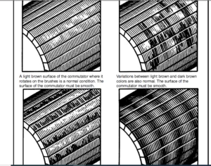
SATISFACTORY SURFACE.......................................................................................... 29
STREAKING AND THREADING SURFACE............................................................................... 30
GROOVING ON SURFACE........................................................................................... 31
COPPER DRAG ON SURFACE........................................................................................ 33
OVERHEATING................................................................................................... 33
FIELD ASSEMBLY................................................................................................ 35
INSPECTION CHECKLIST.......................................................................................... 35
CHECKING AND REPLACING MOTOR BRUSHES.......................................................................... 35
Inspecting Brushes........................................................................................ 35
INSPECT THE COMMUTATOR........................................................................................ 36
REPLACING BRUSHES............................................................................................. 36
SEATING BRUSHES (STONING PROCEDURE)........................................................................... 36
CHECK THE MOTORS FOR OPENS, GROUNDS AND SHORTS................................................................ 37
Check The Motor For Opens................................................................................. 37
Check The Motor For Grounds............................................................................... 37
Check The Motor For Shorts................................................................................ 37
COMMUTATOR INSPECTION......................................................................................... 39
POLISHING COMMUTATOR.......................................................................................... 40
TURNING COMMUTATOR............................................................................................ 40
UNDERCUTTING COMMUTATOR....................................................................................... 40
SLOT RAKING AND BRUSHING COMMUTATOR........................................................................... 40
0620SRM294-897076(03-2003)-EN......................................................................................... 42
toc............................................................................................................... 42
DC Motor Maintenance.......................................................................................... 42
Safety Precautions Maintenance and Repair..................................................................... 43
General....................................................................................................... 46
Brush and Commutator Inspection............................................................................... 46
Hydraulic Pump Motor and Traction Motor................................................................... 46
Steering Pump Motor....................................................................................... 49
Normal Commutator Surface................................................................................. 49
Commutator Problems....................................................................................... 49
Brush Replacement............................................................................................. 53
Stoning the Commutator........................................................................................ 55
Motors Repair................................................................................................. 57
Disassemble............................................................................................... 57
Traction Motor and Hydraulic Pump Motor............................................................... 57
Steering Pump Motor................................................................................... 59
Assemble.................................................................................................. 61
Traction Motor and Hydraulic Pump Motor............................................................... 61
Steering Pump Motor................................................................................... 62
Brush Alignment, Traction and Hydraulic Motors................................................................ 64
Tests for Damaged Field and Armature.......................................................................... 64
Test for an Open Circuit in Armature...................................................................... 64
Test for Short Circuit in One Armature Winding............................................................ 65
Test for Short Circuit to Armature Shaft.................................................................. 65
Test for Open Circuit in Field Coil....................................................................... 65
Test for Short Circuit in Field Coil...................................................................... 66
Test for Short Circuit between Field and Motor Case....................................................... 66
Brush Holder Test......................................................................................... 66
Troubleshooting............................................................................................... 66
tables............................................................................................................ 42
Table 1. Normal Commutator Surfaces........................................................................... 48
Table 2. Commutator Problems.................................................................................. 49
Table 3. Brush Wear Replacement Guide......................................................................... 53
0630SRM794-1482607(05-2000)-EN........................................................................................ 72
toc............................................................................................................... 72
Master Drive Unit (ZF)........................................................................................ 72
Safety Precautions Maintenance and Repair..................................................................... 73
General....................................................................................................... 76
Description................................................................................................... 76
Top Section Housing....................................................................................... 76
Transmission Housing...................................................................................... 76
Repair........................................................................................................ 77
Remove.................................................................................................... 77
Disassemble............................................................................................... 78
Top Section Housing................................................................................... 78
Transmission Housing.................................................................................. 81
Assemble.................................................................................................. 83
Installing Spiral Bevel Pinion Shaft.................................................................. 83
Measuring Bearing Movement in Bevel Pinion Shaft...................................................... 85
Assembly of Helical Gear.............................................................................. 86
Assembling Crown Gear and Wheel Shaft................................................................. 86
Assembling Transmission Housing Cover................................................................. 88
Assembling Input Motor Pinion Gear.................................................................... 88
Inspecting Top Section Housing........................................................................ 88
Measuring Pivoting Bearing Movement................................................................... 89
Installing Top Section Housing........................................................................ 89
Install................................................................................................... 90
Tooth Contact Pattern Adjustment.............................................................................. 91
Changing Transmission Oil..................................................................................... 92
Troubleshooting............................................................................................... 93
tables............................................................................................................ 72
Table 1. Tooth Contact Pattern................................................................................ 91
0630SRM795-1482613(04-2000)-EN........................................................................................ 98
toc............................................................................................................... 98
Master Drive Unit (Kordel).................................................................................... 98
Safety Precautions Maintenance and Repair..................................................................... 99
General.......................................................................................................102
Description...................................................................................................102
Upper Section.............................................................................................102
Lower Section.............................................................................................104
Drive Unit Repair.............................................................................................104
Remove....................................................................................................104
Disassemble...............................................................................................105
Assemble..................................................................................................108
General...............................................................................................108
Assemble Component Subassemblies......................................................................108
Assemble Components Into Lower Section................................................................108
Assemble Upper and Lower Sections.....................................................................109
Install...................................................................................................109
Check and Change Transmission Oil.............................................................................110
Tooth Contact Pattern Adjustment..............................................................................111
Troubleshooting...............................................................................................112
tables............................................................................................................ 98
Table 1. Tooth Contact Pattern................................................................................111
1600SRM485-897450(05-1996)-EN.........................................................................................116
STEERING SYSTEMS FOR ELECTRICAL LIFT TRUCKS.......................................................................116
GENERAL.......................................................................................................116
DESCRIPTION...................................................................................................118
STEERING WHEEL AND COLUMN ASSEMBLY............................................................................119
Removal Of The Assembly Components........................................................................119
Installation Of The Assembly Components...................................................................123
POWER STEERING MOTOR AND PUMP.....................................................................................124
DESCRIPTION...................................................................................................124
REMOVAL AND DISASSEMBLY, E1.25-3.00XL (E25-60XL), J2.00-3.00XL (J40-60XL), E2.00-3.20XM (E45-65XM), N30XMH....124
REMOVAL AND DISASSEMBLY, E3.50-5.50XL (E70-120XL).............................................................124
REMOVAL AND DISASSEMBLY, J2.00-3.20XM (J40-65XM)..............................................................125
REMOVAL AND DISASSEMBLY, A1.00-1.50XL (A20-30XL)..............................................................127
REMOVAL AND DISASSEMBLY, E1.50-2.00XMS (E25-40XMS)............................................................128
ASSEMBLY AND INSTALLATION {All models with a vertical mount except the J2.00-3.20XM (J40-65XM)}...............128
ASSEMBLY AND INSTALLATION, J2.00-3.20XM (J40-65XM)............................................................128
ASSEMBLY AND INSTALLATION, E1.50-2.00XMS (25-40XMS)...........................................................131
REPAIRS, POWER STEERING PUMP..................................................................................132
Seal Replacement..........................................................................................133
HYDRAULIC STEERING MOTOR..........................................................................................133
DESCRIPTION...................................................................................................133
REPAIRS, HYDRAULIC STEERING MOTOR.............................................................................134
Removal...................................................................................................134
Disassembly ..............................................................................................134
Cleaning And Inspection...................................................................................134
Assembly..................................................................................................135
Installation, Hydraulic Steering Motor....................................................................136
CHECKS AND ADJUSTMENTS............................................................................................136
AIR IN THE STEERING SYSTEM....................................................................................136
CHECK STEERING PRESSURE.......................................................................................136
CHECK THE TENSION OF THE STEERING CHAIN (Units With MDU Only).................................................138
CHECK OPTICAL ENCODER AND ACTIVATOR CIRCUITS..................................................................138
TROUBLESHOOTING...................................................................................................140
1600SRM796-1482620(03-2000)-EN........................................................................................142
toc...............................................................................................................142
Steering System...............................................................................................142
Safety Precautions Maintenance and Repair.....................................................................143
General.......................................................................................................146
Description...................................................................................................146
Steering Wheel and Column Assembly........................................................................147
Steering Control Unit Repair..................................................................................151
Remove....................................................................................................151
Install...................................................................................................151
Hydraulic Steering Motor Repair...............................................................................152
Description...............................................................................................152
Remove....................................................................................................152
Disassemble...............................................................................................152
Clean and Inspect.........................................................................................154
Assemble..................................................................................................154
Install...................................................................................................155
Direction Control Lever Repair................................................................................155
Remove....................................................................................................155
Assemble..................................................................................................156
Install...................................................................................................156
Power Steering Adjustments....................................................................................156
Air in Steering System....................................................................................156
Steering Pressure.........................................................................................156
Steering Chain, Adjust....................................................................................157
Troubleshooting...............................................................................................157
1600SRM797-1482617(03-2000)-EN........................................................................................162
toc...............................................................................................................162
Steering Control Unit.........................................................................................162
Safety Precautions Maintenance and Repair.....................................................................163
General.......................................................................................................166
Description...................................................................................................166
Operation.....................................................................................................166
Steering Wheel and Column Assembly Repair.....................................................................168
Steering Column Assembly Repair...............................................................................169
Remove and Disassemble....................................................................................169
Assemble and Install......................................................................................169
Steering Control Unit, Disassemble........................................................................170
Steering Control Unit, Clean..............................................................................172
Steering Control Unit, Assemble...........................................................................173
System Air Removal............................................................................................176
Troubleshooting...............................................................................................177
1800SRM803-1482623(03-2000)-EN........................................................................................182
toc...............................................................................................................182
Brake System..................................................................................................182
Safety Precautions Maintenance and Repair.....................................................................183
General.......................................................................................................186
Description and Operation.....................................................................................186
Master Cylinder Repair........................................................................................188
Remove and Disassemble....................................................................................188
Clean and Inspect.........................................................................................189
Assemble and Install......................................................................................189
Service and Parking Brakes Repair.............................................................................190
Remove and Disassemble....................................................................................190
Clean.....................................................................................................191
Inspect...................................................................................................191
Assemble and Install......................................................................................192
Brake System Air Removal......................................................................................192
Service Brakes Adjustment.....................................................................................193
Brake Pedal Adjustment........................................................................................193
Parking Brake Adjustment......................................................................................194
Troubleshooting...............................................................................................194
1900SRM802-1482626(04-2000)-EN........................................................................................200
toc...............................................................................................................200
Hydraulic System..............................................................................................200
Safety Precautions Maintenance and Repair.....................................................................201
General.......................................................................................................204
Description...................................................................................................204
Control Valve Repair..........................................................................................206
Description...............................................................................................206
Operation.................................................................................................206
Lift..................................................................................................206
Tilt and Auxiliary....................................................................................206
Relief Valve..........................................................................................210
Check Valves..........................................................................................210
Description.......................................................................................210
Clean and Inspect.................................................................................210
Repairs...................................................................................................210
Remove................................................................................................210
Disassemble...........................................................................................211
Relief Valve Repair...................................................................................211
Clean and Inspect.....................................................................................212
Assemble..............................................................................................212
Install...............................................................................................212
Checks....................................................................................................212
Relief Valve Check....................................................................................212
Adjust....................................................................................................213
Relief Valve..........................................................................................213
Control Levers, Linkage and Switches..................................................................213
Hydraulic Pump Repair.........................................................................................215
Description...............................................................................................215
Repairs...................................................................................................215
Remove................................................................................................215
Seal, Replace.........................................................................................216
Install...............................................................................................217
Specifications................................................................................................219
Relief Valves Pressures...................................................................................219
Hydraulic System Capacity.................................................................................219
Troubleshooting...............................................................................................219
Hydraulic Pump............................................................................................219
Control Valve.............................................................................................220
2100SRM103-910102(10-2003)-UK-EN......................................................................................226
toc...............................................................................................................226
Tilt Cylinders................................................................................................226
Safety Precautions Maintenance and Repair.....................................................................227
General.......................................................................................................230
Description...................................................................................................230
Tilt Cylinder Repair..........................................................................................230
Remove....................................................................................................230
Disassemble...............................................................................................230
Clean.....................................................................................................230
Assemble..................................................................................................231
Tilt Cylinders With O-Ring or Single-Lip Seals........................................................231
Tilt Cylinders for XM and XMS Models..................................................................232
Tilt Cylinders for H700-800A and Early Model H700-920B................................................233
Install...................................................................................................234
Tilt Cylinders Using Chevron Packing..................................................................235
Install...........................................................................................236
Tilt Cylinder Leak Check......................................................................................238
Tilt Cylinder Stroke and Mast Tilt Angle Adjustment...........................................................239
Torque Specifications.........................................................................................240
Piston Rod Nut............................................................................................240
Retainer..................................................................................................241
Troubleshooting...............................................................................................243
tables............................................................................................................226
Table 1. Movement Rates (Maximum) for Tilt Cylinders..........................................................239
2200SRM0143-910110(08-2004)-UK-EN.....................................................................................246
toc...............................................................................................................246
Instrument Panel Indicators and Senders.......................................................................246
Safety Precautions Maintenance and Repair.....................................................................247
General.......................................................................................................250
Description...................................................................................................251
Steering Column Gauges, Meters, and Indicators............................................................251
LED Display Panel.........................................................................................251
Battery Discharge Indicators..........................................................................251
Brush Wear Indicators.................................................................................258
Motor Temperature Indicators..........................................................................258
LX Series Display Panel...................................................................................260
Hourmeter Functions...................................................................................260
Battery Indicator Function............................................................................261
Status Code Function..................................................................................262
ZX Series Display Panels..................................................................................262
Display Panel.........................................................................................262
Basic Display Panels..................................................................................262
Performance Display...................................................................................265
Brush Wear Indicators.................................................................................268
Adjustments - General.........................................................................................269
Replacement - General Information.............................................................................269
Meter Replacement.............................................................................................270
Sender Replacement............................................................................................271
Fuel Level Sender.........................................................................................271
Pressure and Temperature Sender...........................................................................271
ITW Display Panel Replacement.................................................................................272
Remove....................................................................................................272
Column Mount Display Panel (EV-100/200ZX Motor Controllers) Repl..............................................273
Remove....................................................................................................273
Display Panel Assembly, Replace...........................................................................273
Indicator LEDs............................................................................................274
Battery Indicators........................................................................................274
Digital Display (Performance Display Panel Only)..........................................................274
Status Code or Performance Level Switches and Indicator LEDs (Pe..........................................274
Basic Display Panel, Replace Parts........................................................................274
Performance Display Panel, Replace Parts..................................................................276
Dash Mount Display Panel (EV100/200ZX Motor Controllers) Replace..............................................277
Remove and Replace........................................................................................277
Specifications................................................................................................277
Meter Specifications......................................................................................277
Sender Specifications.....................................................................................278
Troubleshooting...............................................................................................278
Meter.....................................................................................................278
2200SRM0144-910111(05-1997)-EN........................................................................................282
ELECTRICAL WARNING DEVICES........................................................................................282
GENERAL.......................................................................................................282
DESCRIPTION...................................................................................................282
Operator Controlled Horns.................................................................................282
System Warning Lights, Buzzers and Bells..................................................................282
Reverse Warning Horns.....................................................................................283
Warning Lights............................................................................................283
REPLACEMENT...................................................................................................284
General...................................................................................................284
Replacing Horns or Bells..................................................................................284
Replacing Horn Relay or Buzzer............................................................................284
Replacing Warning Lights..................................................................................284
Light Assemblies..........................................................................................285
Replacing Flashing Units..................................................................................285
2200SRM0806-1482629(10-2001)-EN.......................................................................................286
toc...............................................................................................................286
Sevcon® SC2126 Motor Controller...............................................................................286
Safety Precautions Maintenance and Repair.....................................................................287
General.......................................................................................................290
Lift Truck Control........................................................................................290
Plugging..................................................................................................291
Contactors................................................................................................291
Circuit Protection........................................................................................292
Current Limit.........................................................................................292
Fuses.................................................................................................292
Controller Operation..........................................................................................293
General Operation.........................................................................................293
Operating Frequency...................................................................................293
Temperature Monitoring................................................................................293
Safe Operating Area (SOA).............................................................................293
Undervoltage and Overvoltage Protection...............................................................293
Diagnostic LED........................................................................................294
Fault Clearance.......................................................................................294
Software Version and Revision Indication..............................................................294
Setup Menu............................................................................................294
Multi Languages.......................................................................................294
Power Circuit Descriptions....................................................................................294
Traction Operation........................................................................................295
Start Up Sequence.....................................................................................295
Static Return to Off (SRO)............................................................................295
Seat Switch...........................................................................................295
Acceleration Delay....................................................................................295
Deceleration Delay....................................................................................295
Creep.................................................................................................295
Regenerative Braking..................................................................................295
Plug Braking..........................................................................................296
Brake Constant Factor.................................................................................296
Antirollback..........................................................................................296
Analog Inputs.........................................................................................296
Traction Accelerator..................................................................................296
Digital Switch Inputs.................................................................................296
Contactors............................................................................................297
Contactor Chopping....................................................................................297
Fail-Safe.............................................................................................297
Pump Operation............................................................................................297
Pump Speeds and Priorities............................................................................298
Additive Speeds.......................................................................................298
Power Steer Speed.....................................................................................298
Pump Inhibit Input....................................................................................298
Pump Speed Compensation...............................................................................298
Calibration and Adjustments...................................................................................299
Traction Personalities (Controller Adjustments)...........................................................299
Traction Status Information...............................................................................301
Traction Test Information.................................................................................301
BDI Adjustments...........................................................................................302
Fault Log.................................................................................................302
Setup Menu (Enables/Disables Features)....................................................................302
Pump Personalities (Controller Adjustments)...............................................................302
Pump Status Information...................................................................................303
Pump Test Information.....................................................................................304
Pump Setup Menu...........................................................................................304
Traction and Pump Adjustment Descriptions.................................................................304
Setup Menu Descriptions...................................................................................306
Controller Connections........................................................................................307
Power Connections.........................................................................................307
Controller Connections................................................................................307
Contactor Connections.................................................................................307
Contactor Types.......................................................................................307
Fuse Ratings..........................................................................................307
Back Panel Connectors.....................................................................................307
Connector A - 24 Pin..................................................................................308
Connector B - 12 Pin..................................................................................308
Connector C - 6 Pin...................................................................................309
Controller Area Network (CAN) Overview....................................................................309
Diagnostics...................................................................................................309
Service and Fault Logs........................................................................................311
Service Log...............................................................................................311
Fault Log.................................................................................................311
Technical Specifications......................................................................................312
Environmental.............................................................................................312
Mechanical................................................................................................312
Electrical................................................................................................312
Voltage Specifications:...............................................................................312
Current Specifications:...............................................................................313
Miscellaneous Controller Specifications:..............................................................313
Contactor Repair..............................................................................................314
General...................................................................................................316
Remove Contactor Assembly.................................................................................316
Contactor Contacts........................................................................................316
Coil......................................................................................................316
Control Switches..............................................................................................318
Key Switch................................................................................................318
Seat Switch...............................................................................................318
Start Switch..............................................................................................318
Brake Pedal Adjustment........................................................................................318
Accelerator Pedal Adjustment..................................................................................319
tables............................................................................................................286
Table 1. Over- and Undervoltage Protection....................................................................293
2200SRM1014-1515047(11-2001)-EN.......................................................................................322
toc...............................................................................................................322
Sevcon Traction and Pump Controllers..........................................................................322
Safety Precautions Maintenance and Repair.....................................................................323
Sevcon PCpak..................................................................................................328
Introduction..............................................................................................328
System Requirements.......................................................................................328
Traction Controller Safety....................................................................................328
Traction Controller Introduction..............................................................................329
Traction Controller Installation..............................................................................329
Mounting..................................................................................................329
Traction Controller Calibration...............................................................................331
Adjustments...............................................................................................331
Status and Test Information...............................................................................332
Traction Controller Configuration.............................................................................333
System Configuration......................................................................................333
System Voltage............................................................................................333
System I/O Configuration..................................................................................333
System/Motor Setup........................................................................................335
Armature Field Map........................................................................................335
Armature and Field Current Limit..........................................................................336
Contactor Chopping........................................................................................337
Accelerator Full/Zero Setting.............................................................................337
Performance...............................................................................................337
Acceleration Delay........................................................................................337
Deceleration Delay........................................................................................337
Control Mode..............................................................................................338
Plugging..................................................................................................338
Types of Braking..........................................................................................338
Braking Levels............................................................................................338
Footbraking...............................................................................................338
Footbrake Pot.............................................................................................339
Footbrake Priority........................................................................................340
Creep Speed...............................................................................................340
Maximum Speed.............................................................................................340
Traction Controller Commissioning.............................................................................340
Checklist.................................................................................................340
Traction Controller Features..................................................................................342
Accelerator Characteristics...............................................................................342
Features..................................................................................................343
Standard Controller Features..............................................................................343
Power Steer...............................................................................................343
High Speed Switch and Anti-Tie Down.......................................................................344
Seat Switch...............................................................................................345
Traction Drive Hours Meter................................................................................345
Personality Checksum......................................................................................345
Reverse Buzzer............................................................................................345
Traction Controller Safety Features...........................................................................345
Start Up Sequence.........................................................................................345
SRO (Static Return to Off)................................................................................345
Belly Switch (not used)...................................................................................346
Anti-Rollback.............................................................................................346
Anti-Rolloff..............................................................................................346
Fail-Safe.................................................................................................346
Traction Controller Protection................................................................................346
Controller Protection Features............................................................................346
Temperature Monitoring....................................................................................346
Maximum Temperature Logging...............................................................................347
Timed Current Cutback.....................................................................................347
Safe Operating Area (SOA).................................................................................348
Under-Voltage and Over-Voltage Protection.................................................................349
Traction Controller Diagnostics...............................................................................350
Fault Codes...............................................................................................350
Fault Code Clearance......................................................................................351
Software Version and Serial Number Indication.............................................................351
Traction Controller Specifications............................................................................352
Power Configurations......................................................................................352
EMC Standards.............................................................................................352
Socket B Protection.......................................................................................352
Contactor Drive Ratings...................................................................................352
Analogue Input Impedance..................................................................................352
Digital Input Impedance...................................................................................352
EMC Guidelines............................................................................................352
Power Cables..............................................................................................353
Signal Cables.............................................................................................353
Controller................................................................................................353
Pump Controller Safety........................................................................................353
Pump Controller Introduction..................................................................................353
Pump Controller Installation..................................................................................354
Mounting..................................................................................................354
MillipaK Pump Power Wiring................................................................................354
Pump Controller Calibration...................................................................................355
Adjustments...............................................................................................355
Status and Test Information...............................................................................356
Pump Controller Configuration.................................................................................357
System Configuration......................................................................................357
System Voltage............................................................................................357
System I/O Configuration..................................................................................357
Current Limit.............................................................................................358
Accelerator Full/Zero Setting.............................................................................358
Performance...............................................................................................359
Lift and Power Steer Ramps................................................................................359
Creep Speed...............................................................................................359
Maximum Speed.............................................................................................359
Pump Controller Commissioning.................................................................................360
Under-Voltage Protection..................................................................................360
Commissioning Checklist...................................................................................360
Personalities Record......................................................................................361
Pump Controller Features......................................................................................362
Features..................................................................................................362
Standard Controller Features..............................................................................362
Lift Switch Inputs - Priority.............................................................................362
Lift Switch Inputs - Additive.............................................................................363
Compensation..............................................................................................363
Power Steer Input.........................................................................................363
Lift Inhibit Input........................................................................................364
Cooling Fan...............................................................................................364
Pump Hours Meter..........................................................................................364
Personality Checksum......................................................................................364
Pump Controller Safety Features...............................................................................364
Fail-safe.................................................................................................364
Pump Controller Protection....................................................................................364
Controller Protection Features............................................................................364
Temperature Monitoring....................................................................................364
Maximum Temperature Logging...............................................................................365
Timed Current Cutback.....................................................................................365
Safe Operating Area (SOA).................................................................................366
Pump Controller Diagnostics...................................................................................366
Diagnostics...............................................................................................366
Fault Clearance...........................................................................................367
Using Status and Test Menus...............................................................................367
Software Version and Serial Number Indication.............................................................368
Pump Controller Specifications................................................................................369
Power Configurations......................................................................................369
EMC Standards.............................................................................................369
Socket B Protection.......................................................................................369
Contactor Drive Ratings...................................................................................369
Analogue Input Impedance..................................................................................369
Digital Input Impedance...................................................................................369
Ordering Information..........................................................................................370
EMC Guidelines............................................................................................370
Power Cables..............................................................................................370
Signal Cables.............................................................................................370
Controller................................................................................................370
tables............................................................................................................322
Table 1. Adjustment Menus.....................................................................................331
Table 2. Status and Test Information Menus....................................................................332
Table 3. Description of each Digital I/O Configuration........................................................333
Table 4. Digital Functions....................................................................................334
Table 5. Pin Allocations......................................................................................335
Table 6. Analogue Functions...................................................................................335
Table 7. Personality Record...................................................................................340
Table 8. Internal Power Steer Triggers........................................................................343
Table 9. Timed Current Limit Cutback Levels...................................................................347
Table 10. Under- and Over-Voltage Cutback Levels..............................................................349
Table 11. Flash Fault Descriptions............................................................................350
Table 12. Fault Codes and Descriptions........................................................................350
Table 13. Software Version Format.............................................................................351
Table 14. Serial Number Format................................................................................352
Table 15. Power Configurations................................................................................352
Table 16. Analogue Function...................................................................................358
Table 17. Personality Record..................................................................................361
2240SRM001-899648(03-2003)-EN.........................................................................................374
toc...............................................................................................................374
Industrial Battery............................................................................................374
Safety Precautions Maintenance and Repair.....................................................................375
General.......................................................................................................378
Lead-Acid Batteries...........................................................................................378
Specific Gravity..............................................................................................379
Chemical Reaction in a Cell...................................................................................379
Electrical Terms..............................................................................................380
Battery Selection.............................................................................................381
Battery Voltage...............................................................................................382
Battery as a Counterweight....................................................................................382
Battery Ratings...............................................................................................382
Kilowatt-Hours............................................................................................382
Battery Maintenance...........................................................................................383
Safety Procedures.........................................................................................383
Maintenance Records.......................................................................................383
New Battery...............................................................................................383
Cleaning Battery..........................................................................................384
Adding Water to Battery...................................................................................385
Hydrometer................................................................................................386
Battery Temperature.......................................................................................386
Charging Battery..........................................................................................387
Types of Battery Charges..............................................................................388
Methods of Charging...................................................................................389
Troubleshooting Charger...............................................................................390
Knowing When Battery Is Fully Charged.................................................................390
Where to Charge Batteries.................................................................................390
Equipment Needed......................................................................................390
Battery Connectors........................................................................................391
Battery Care..............................................................................................391
tables............................................................................................................374
Table 1. Battery Capacity Terms...............................................................................382
2260SRM138-910114(10-2000)-EN.........................................................................................396
INTRODUCTION......................................................................................................396
GENERAL.......................................................................................................396
INDICATORS WITH METER MOVEMENTS...............................................................................397
BATTERY INDICATORS WITH LCD OR LED DISPLAYS...................................................................398
Liquid Crystal Displays...................................................................................398
Light Emitting Diode Displays.............................................................................399
CHECKS AND ADJUSTMENTS............................................................................................402
BATTERY INDICATORS WITHOUT LIFT INTERRUPT, EARYLY MODELS......................................................402
BATTERY INDICATORS WITH LIFT INTERRUPT, EARLY MODELS..........................................................403
Reset Potentiometer.......................................................................................403
Specific Gravity Alarm....................................................................................403
BATTERY INDICATORS WITHOUT LIFT INTERRUPT, LATER MODELS.......................................................403
BATTERY INDICATORS WITH LIFT INTERRUPT, LATER MODELS..........................................................403
Reset Potentiometer.......................................................................................404
Discharge Potentiometer...................................................................................404
LED DISPLAY WITH LIFT INTERRUPT...............................................................................404
CHECKING CURTIS 933-1 METER...................................................................................404
Reset Check ..............................................................................................405
Discharge Check...........................................................................................405
Lockout Check.............................................................................................406
Hour Glass Icon...........................................................................................406
ADJUSTMENT OF CURTIS 933-1 METER..............................................................................407
CHECKING CURTIS 1215 BATTERY INDICATOR........................................................................407
ADJUSTING CURTIS 1215 BATTERY INDICATOR.......................................................................408
Voltage Selection.........................................................................................409
REPAIRS...........................................................................................................410
BATTERY INDICATORS................................................................................................410
Replacement...................................................................................................410
CONTROLLER FOR THE BATTERY INDICATOR..............................................................................410
Replacement...................................................................................................410
DISPLAY PANEL COMPONENTS..........................................................................................410
4000SRM222-899237(04-2000)-EN.........................................................................................411
INTRODUCTION......................................................................................................411
GENERAL.......................................................................................................411
MAST WELDMENTS................................................................................................411
CARRIAGE......................................................................................................411
MAST MOUNTS...................................................................................................412
VISTA® TWO-STAGE MAST.............................................................................................413
DESCRIPTION AND OPERATION.....................................................................................413
VISTA® FREE-LIFT MAST.............................................................................................415
DESCRIPTION...................................................................................................415
OPERATION.....................................................................................................415
VISTA® THREE-STAGE MAST...........................................................................................417
DESCRIPTION...................................................................................................417
OPERATION.....................................................................................................417
VISTA® FOUR-STAGE MAST............................................................................................418
DESCRIPTION...................................................................................................418
OPERATION.....................................................................................................419
4000SRM374-897209(03-1993)-EN.........................................................................................421
SAFETY PROCEDURES WHEN WORKING NEAR THE MAST......................................................................421
INTRODUCTION......................................................................................................422
GENERAL.......................................................................................................422
FORKS.........................................................................................................422
CARRIAGE......................................................................................................423
Removal...................................................................................................423
Installation..............................................................................................423
MAST..............................................................................................................424
REMOVAL FROM THE LIFT TRUCK...................................................................................424
DISASSEMBLY...................................................................................................425
Two-Stage And Free-Lift Masts.............................................................................425
Three-Stage Mast..........................................................................................426
CLEANING AND INSPECTION.......................................................................................428
ASSEMBLY......................................................................................................429
Two-Stage And Free-Lift Mast..............................................................................429
Two-Stage Mast............................................................................................430
Free-Lift Mast............................................................................................430
Three-Stage Mast..........................................................................................430
INSTALLATION..................................................................................................431
LIFT CYLINDERS....................................................................................................432
DESCRIPTION...................................................................................................432
LOWERING CONTROL VALVE........................................................................................434
REMOVAL OF THE LIFT CYLINDERS WITHOUT REMOVING THE MAST.......................................................435
DISASSEMBLY...................................................................................................436
Main Lift Cylinders.......................................................................................436
Free-lift Cylinder........................................................................................436
ASSEMBLY......................................................................................................436
Main Lift Cylinders.......................................................................................436
Free-Lift Cylinders.......................................................................................436
INSTALLATION OF THE LIFT CYLINDERS INTO THE MASTS.............................................................437
Main Lift Cylinders.......................................................................................437
Free-Lift Cylinder........................................................................................437
TILT CYLINDER.................................................................................................437
DESCRIPTION...................................................................................................437
REMOVAL.......................................................................................................438
DISASSEMBLY...................................................................................................438
CLEANING......................................................................................................438
ASSEMBLY......................................................................................................438
INSTALLATION..................................................................................................438
SIDE-SHIFT CARRIAGE...........................................................................................439
Removal...................................................................................................439
Removal...................................................................................................439
Repairs...................................................................................................439
Installation..............................................................................................440
CHECKS AND ADJUSTMENTS............................................................................................442
CHECK FOR LEAKS IN THE LIFT AND TILT SYSTEM...................................................................442
Check The Lift Cylinder For Leaks.........................................................................442
Check The Tilt Cylinder For Leaks.........................................................................443
ADJUSTMENT OF THE TILT CYLINDER STROKE AND THE BACKWARD TILT ANGLE............................................443
LIFT CHAIN ADJUSTMENTS........................................................................................443
MAST ADJUSTMENTS..............................................................................................444
CARRIAGE ADJUSTMENT...........................................................................................446
SIDE-SHIFT CYLINDER ADJUSTMENT................................................................................446
8000SRM231-910442(03-2004)-EN.........................................................................................448
toc...............................................................................................................448
Metric and Inch (SAE) Fasteners...............................................................................448
Safety Precautions Maintenance and Repair.....................................................................449
General.......................................................................................................452
Threaded Fasteners........................................................................................452
Nomenclature, Threads.....................................................................................452
Strength Identification...................................................................................453
Cotter (Split) Pins.......................................................................................453
Fastener Torque Tables....................................................................................458
Conversion Table..........................................................................................460
tables............................................................................................................448
Table 1. Bolts and Screws.....................................................................................454
Table 2. Studs and Nuts.......................................................................................455
Table 3. Torque Nuts..........................................................................................456
Table 4. Torque Nuts With Nylon Insert........................................................................457
Table 5. Torque Values for Metric Fasteners*..................................................................458
Table 6. Torque Values for Inch Fasteners*....................................................................459
Table 7. Conversion Table for Metric and English Units........................................................460
Table 8. Cotter Pin Dimensional Data..........................................................................461
Table 9. Cotter Pin Dimensional Data..........................................................................462
Table 10. Cotter Pin Dimensional Data.........................................................................463
Table 11. Cotter Pin Dimensional Data.........................................................................465
8000SRM798-1482632(03-2000)-EN........................................................................................468
toc...............................................................................................................468
Periodic Maintenance..........................................................................................468
Safety Precautions Maintenance and Repair.....................................................................469
General.......................................................................................................472
How to Move Disabled Lift Truck...........................................................................472
How to Tow Lift Truck.................................................................................472
How to Put Lift Truck on Blocks...........................................................................473
How to Raise Load Wheels..............................................................................473
How to Raise Steer Wheels.............................................................................474
Safety Procedures When Working Near Mast......................................................................474
Maintenance Schedule..........................................................................................476
Maintenance Procedures Every 8 Hours or Daily.................................................................478
Checks Before Operation...................................................................................478
Hydraulic System......................................................................................478
Battery...............................................................................................479
Battery Restraint System..............................................................................479
Operator Restraint System.............................................................................480
Mast, Forks, and Lift Chains..........................................................................480
Lift Chain Adjustments................................................................................482
Tires and Wheels......................................................................................482
Check Operation...........................................................................................483
Gauges and Horn.......................................................................................483
Control Levers and Pedals.............................................................................483
Lift System Operation.................................................................................483
Service Brakes........................................................................................484
Parking Brake.........................................................................................484
Steering System.......................................................................................484
Maintenance Procedures Every 500 Hours or 2 Months............................................................484
Hydraulic Tank Breather...................................................................................484
Wheel Nut Torques.........................................................................................484
Master Drive Unit (MDU)...................................................................................484
Mast......................................................................................................485
Lift Chains...............................................................................................485
Forks.....................................................................................................486
Safety Labels.............................................................................................486
Brake Fluid...............................................................................................486
Other Lubrication.........................................................................................486
Electrical Inspection.....................................................................................487
Contactors............................................................................................487
Motor Brushes.........................................................................................487
Maintenance Procedures Every 2000 Hours or Yearly.............................................................488
Hydraulic System..........................................................................................488
Change Hydraulic Oil Filter...........................................................................488
Change Hydraulic Oil..................................................................................488
Brake Shoes...............................................................................................488
Steering System...........................................................................................488
Master Drive Unit.........................................................................................488
Adjust Service Brakes.....................................................................................489
Adjust Parking Brake......................................................................................489
Lift and Tilt System Leak Check...............................................................................490
Lift System...............................................................................................490
Tilt System...............................................................................................491
Battery Maintenance...........................................................................................491
How to Charge Battery.....................................................................................491
How to Change Battery.....................................................................................492
Battery Size Specifications...............................................................................493
Wheel and Tire Maintenance....................................................................................494
General...................................................................................................494
How to Change Tires.......................................................................................494
Solid Rubber Tires on Pneumatic Wheels....................................................................494
Remove Wheels From Lift Truck.........................................................................494
Remove Solid Rubber Tire From Pneumatic Wheel.........................................................495
Install Solid Rubber Tire on Pneumatic Wheel..........................................................496
Wheels, Install.......................................................................................497
tables............................................................................................................468
Table 1. Maintenance Schedule.................................................................................477
Table 2. Battery Size Specifications - Type: Lead-Acid Battery................................................493
8000SRM804-1482635(04-2000)-EN........................................................................................500
toc...............................................................................................................500
Capacities and Specifications.................................................................................500
Safety Precautions Maintenance and Repair.....................................................................501
Wheels and Tires..............................................................................................504
Hydraulic System..............................................................................................504
Motors (24 Volt)..............................................................................................504
Mast Creep Speeds.............................................................................................504
Mast Speeds...................................................................................................505
Battery Size Specifications...................................................................................506
Torque Specifications.........................................................................................506
Frame.....................................................................................................506
Master Drive Unit (MDU) (ZF Gotha)........................................................................506
Master Drive Unit (MDU) (Kordel)..........................................................................506
Steering System...........................................................................................506
Brake System..............................................................................................507
Hydraulic System..........................................................................................507
Mast......................................................................................................507
Wheels....................................................................................................507
Sevcon SC2126 Motor Controller Adjustments....................................................................507
8000SRM805-1482638(10-2001)-EN........................................................................................510
Schematics........................................................................................................512
Figure 1. Lift Truck Control Wire Diagram Last Used 10/01.....................................................512
Figure 2. Electrical Connection Diagram.......................................................................517
Figure 3. Hydraulic Schematic.................................................................................519
Figure 4. Control Unit Connector Layout.......................................................................520
Figure 5. Control Wire Diagrams First Used 10/01..............................................................521
Figure 6. Control Unit Connector Diagrams First Used 10/01....................................................523
HYSTER C203 (A1.00-1.50XL A20-30XL) SERVICE MANUAL – PDF DOWNLOAD:
IMAGES PREVIEW OF THE MANUAL:
PLEASE NOTE:
- This is the SAME exact manual used by your dealers to fix your vehicle.
- The same can be yours in the next 2-3 mins as you will be directed to the download page immediately after paying for the manual.
- Any queries / doubts regarding your purchase, please feel free to contact [email protected]
S.V