Trusted Business
Verified & Licensed
Virus Free Files
100% Safe Downloads
Secure Payment
SSL Protected
Instant Delivery
Available Immediately
Sale!


Hyster CHALLENGER H1.50XM H1.75XM H2.00XMS (E001) Parts Manual – PDF DOWNLOAD
Original price was: $89.95.$29.95Current price is: $29.95.
Hyster CHALLENGER H1.50XM H1.75XM H2.00XMS (E001) Parts Manual – PDF DOWNLOAD
Instant PDF Download
Available immediately
Save to Your Device
Download & keep forever
Antivirus Scanned
100% virus-free
Trusted Worldwide
175,000+ customers
Description
Hyster CHALLENGER H1.50XM H1.75XM H2.00XMS (E001) Parts Manual – PDF DOWNLOAD
DESCRIPTION:
Hyster CHALLENGER H1.50XM H1.75XM H2.00XMS (E001) Parts Manual – PDF DOWNLOAD
HOW TO USE THE ILLUSTRATED PARTS MANUAL :
- This parts manual describes and illustrates assemblies, sub-assemblies, and detail parts needed for service replacement.
- The different constructions are indicated by keys and footnotes. The call outs correspond to descriptions found on the next page.
HOW TO FIND THE DESIRED PART NUMBER
WHEN THE PART NUMBER AND THE NEXT HIGHER ASSEMBLY IS NOT KNOWN:
1. Determine the function and application of the part required. Turn to the Sections Page. Choose the general area of reference most likely to include the part.
WHEN THE PART NUMBER AND THE NEXT HIGHER ASSEMBLY IS NOT KNOWN:
1. Determine the function and application of the part required. Turn to the Sections Page. Choose the general area of reference most likely to include the part.
2. Turn to the section you chose. Use the Section Table of Contents to determine the assembly which would normally contain the part required. Then locate the part on the assembly breakdown page.
WHEN THE PART NUMBER IS NOT KNOWN AND THE NEXT HIGHER ASSEMBLY IS KNOWN:
3. Determine the assembly the required part is used on. Turn to the Table of Contents (Page i).
WHEN THE PART NUMBER IS NOT KNOWN AND THE NEXT HIGHER ASSEMBLY IS KNOWN:
3. Determine the assembly the required part is used on. Turn to the Table of Contents (Page i).
4. Locate the assembly the required part is used on and turn to the page indicated for that assembly. Then locate the part on the assembly breakdown page.
WHEN THE PART NUMBER IS KNOWN:
5. Use the Numerical Index (Page 13-1) to find the part number. Turn to the page listed and locate the part as indicated by the item number.
GENERAL:
The assembly breakdowns include part numbers, descriptions, quantities required, keys and footnotes to help in selecting correct parts.
6. Parts Super session Information. Part numbers that have this history will be displayed in the parts list in the order that they were superseded (from oldest to newest). The superseded part numbers will be shown with a line through them.
- Five periods in the PART NO. column (. . . . .) indicate that the part is either Not Serviced Separately or there is a reference to another figure. A figure reference is denoted by a pointing hand followed by a figure number in the DESCRIPTION column (Figure 10)
7. Keys are used to show two or more similar assemblies, RH and LH assembly parts, etc. Select the appropriate key, “A”, “B”, “C”, “D”, or “E” and the corresponding quantity column to find the required parts. Two periods in the QTY column (..) indicate that the part is not used for that assembly.
TABLE OF CONTENTS:
Hyster CHALLENGER H1.50XM H1.75XM H2.00XMS (E001) Parts Manual – PDF DOWNLOAD
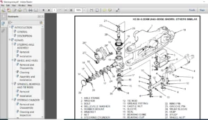
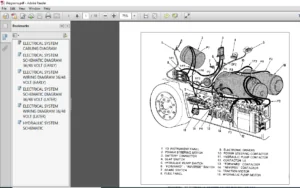
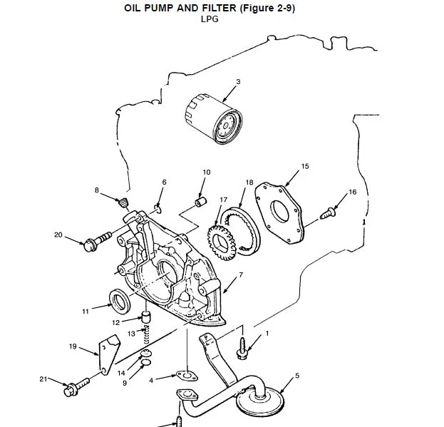
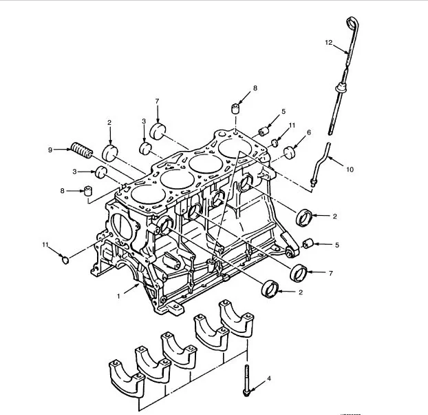
toc..........................................................  1
	1........................................................ 19
		FRAME AND FLOORPLATE (Figure 1-1).................... 22
		FENDER (Figure 1-2).................................. 24
		OVERHEAD GUARD (Figure 1-3).......................... 26
		ENGINE COVER (Figure 1-4)............................ 28
		SEAT (Figure 1-5).................................... 30
		SEAT (Figure 1-6).................................... 32
		SEAT (Figure 1-7).................................... 34
		LABELS (Figure 1-8).................................. 36
		COUNTERWEIGHT (Figure 1-9)........................... 40
		NOISE REDUCTION (Figure 1-10)........................ 42
		NOISE REDUCTION (Figure 1-11)........................ 44
	2........................................................ 47
		CYLINDER HEAD (Figure 2-1)........................... 50
		CYLINDER BLOCK (Figure 2-2).......................... 52
		TIMING GEAR COVER AND OIL SUMP (Figure 2-3).......... 54
		CRANKSHAFT AND PISTON (Figure 2-4)................... 56
		CAMSHAFT AND VALVES (Figure 2-5)..................... 58
		INTAKE AND EXHAUST MANIFOLD (Figure 2-6)............. 60
		ENGINE ELECTRICAL SYSTEM (Figure 2-7)................ 62
		ENGINE FUEL SYSTEM (Figure 2-8)...................... 64
		OIL PUMP AND FILTER (Figure 2-9)..................... 66
		COOLING SYSTEM (Figure 2-10)......................... 68
		RADIATOR AND HOSES (Figure 2-11)..................... 70
		ENGINE MOUNT (Figure 2-12)........................... 72
		CYLINDER HEAD (Figure 2-13).......................... 74
		CYLINDER BLOCK (Figure 2-14)......................... 76
		TIMING GEAR COVER AND OIL SUMP (Figure 2-15)......... 78
		CRANKSHAFT AND PISTON (Figure 2-16).................. 80
		CAMSHAFT AND VALVES (Figure 2-17).................... 82
		INTAKE AND EXHAUST MANIFOLD (Figure 2-18)............ 84
		OIL PUMP AND FILTER (Figure 2-19).................... 86
		COOLING SYSTEM (Figure 2-20)......................... 88
		RADIATOR AND HOSES (Figure 2-21)..................... 90
		ENGINE ELECTRICAL SYSTEM (Figure 2-22)............... 92
		ENGINE MOUNT (Figure 2-23)........................... 94
		COUNTERWEIGHT EXHAUST (Figure 2-24).................. 96
		EXHAUST (Figure 2-25)................................ 98
		UPSWEPT EXHAUST (Figure 2-26)........................100
		UPSWEPT EXHAUST (Figure 2-27)........................102
	3........................................................105
		THROTTLE ASSEMBLY (Figure 3-1).......................108
		MONOTROL PEDAL (Figure 3-2)..........................110
		THROTTLE LINKAGE (Figure 3-3)........................112
		THROTTLE LINKAGE (Figure 3-4)........................113
		AIR FILTER (Figure 3-5)..............................114
		AIR FILTER (Figure 3-6)..............................116
		TANK (Figure 3-7)....................................118
		FUEL SYSTEM (Figure 3-8).............................120
		CARBURETTOR (Figure 3-9).............................124
		REGULATOR (Figure 3-10)..............................126
		GOVERNOR (Figure 3-11)...............................128
		FUEL SYSTEM (Figure 3-12)............................130
		NOZZLE HOLDER (Figure 3-13)..........................132
		FUEL FILTER (Figure 3-14)............................134
		INJECTION PUMP (Figure 3-15).........................136
		FUEL TANK AND LINES (Figure 3-16)....................138
	4........................................................141
		ELECTRICAL SYSTEM (Figure 4-1).......................144
		ELECTRICAL SYSTEM (Figure 4-2).......................148
		ELECTRICAL (Figure 4-3)..............................150
		INSTRUMENT CLUSTER (Figure 4-4)......................154
		LEVER (Figure 4-5)...................................156
		BATTERY (Figure 4-6).................................158
		WIRE HARNESS (Figure 4-7)............................160
		WIRE HARNESS (Figure 4-8)............................162
		WIRE HARNESS (Figure 4-9)............................163
		WIRE HARNESS (Figure 4-10)...........................164
		WIRE HARNESS (Figure 4-11)...........................165
		WIRE HARNESS (Figure 4-12)...........................166
		WIRE HARNESS (Figure 4-13)...........................167
		DISTRIBUTOR (Figure 4-14)............................168
		STARTER MOTOR (Figure 4-15)..........................170
		STARTER MOTOR (Figure 4-16)..........................172
		ALTERNATOR (Figure 4-17).............................174
	5........................................................177
		TORQUE CONVERTER (Figure 5-1)........................180
		CHARGE PUMP (Figure 5-2).............................182
		SOLENOID VALVE (Figure 5-3)..........................183
		TRANSMISSION HOUSING (Figure 5-4)....................184
		TRANSMISSION GEARS (Figure 5-5)......................186
		TRANSMISSION HYDRAULIC LINES (Figure 5-6)............188
		HYDRAULIC CLUTCH (Figure 5-7)........................190
		CONTROL VALVE (Figure 5-8)...........................192
		DIFFERENTIAL (Figure 5-9)............................194
		DRIVE AXLE (Figure 5-10).............................196
		END PLATE (Figure 5-11)..............................198
	6........................................................201
		STEERING COLUMN (Figure 6-1).........................204
		STEERING HAND PUMP (Figure 6-2)......................206
		TRAIL AXLE (Figure 6-3)..............................208
		STEERING CYLINDER (Figure 6-4).......................210
	7........................................................211
		BRAKE LINKAGE (Figure 7-1)...........................214
		BRAKE LINES (Figure 7-2).............................216
		BRAKE ASSEMBLY (Figure 7-3)..........................218
		PARK BRAKE LEVER (Figure 7-4)........................220
		BRAKE MASTER CYLINDER (Figure 7-5)...................222
	8........................................................225
		HYDRAULICS GROUP (Figure 8-1)........................228
		HYDRAULIC PUMP (Figure 8-2)..........................232
		HYDRAULIC PUMP (Figure 8-3)..........................234
		PUMP DRIVE (Figure 8-4)..............................236
		VALVE ATTACHING PARTS (Figure 8-5)...................238
		CONTROL VALVE (Figure 8-6)...........................242
		VALVE ATTACHING PARTS (Figure 8-7)...................246
		CONTROL VALVE (Figure 8-8)...........................248
		TILT CYLINDER (Figure 8-9)...........................251
		TILT CYLINDER (Figure 8-10)..........................252
		TILT CYLINDER (Figure 8-11)..........................253
	9........................................................255
		OUTER MAST (Figure 9-1)..............................258
		INNER MAST (Figure 9-2)..............................260
		FREE LIFT (Figure 9-3)...............................262
		LIFT CYLINDER (Figure 9-4)...........................264
		LIFT CYLINDER (Figure 9-5)...........................266
		CARRIAGE (Figure 9-6)................................268
		LOAD BACKREST EXTENSION (Figure 9-7).................270
		MAST INSTALLATION (Figure 9-8).......................272
		HEADER HOSE (Figure 9-9).............................274
		HEADER HOSE (Figure 9-10)............................276
		FORK (Figure 9-11)...................................278
		FORK (Figure 9-12)...................................279
	10.......................................................281
		OUTER MAST (Figure 10-1).............................284
		INNER MAST (Figure 10-2).............................286
		MAIN LIFT (Figure 10-3)..............................288
		FREE LIFT (Figure 10-4)..............................290
		MAIN CYLINDER (Figure 10-5)..........................292
		MAIN CYLINDER (Figure 10-6)..........................294
		FREE-LIFT CYLINDER (Figure 10-7).....................296
		CARRIAGE (Figure 10-8)...............................298
		LOAD BACKREST EXTENSION (Figure 10-9)................300
		MAST INSTALLATION (Figure 10-10).....................302
		HEADER HOSE (Figure 10-11)...........................304
		HEADER HOSE (Figure 10-12)...........................308
		FORK (Figure 10-13)..................................311
		FORK (Figure 10-14)..................................312
	11.......................................................313
		OUTER MAST (Figure 11-1).............................316
		INTERMEDIATE MAST (Figure 11-2)......................318
		INNER MAST (Figure 11-3).............................320
		MAIN LIFT (Figure 11-4)..............................322
		FREE LIFT (Figure 11-5)..............................324
		MAIN CYLINDER (Figure 11-6)..........................326
		MAIN CYLINDER (Figure 11-7)..........................328
		FREE-LIFT CYLINDER (Figure 11-8).....................330
		CARRIAGE (Figure 11-9)...............................332
		LOAD BACKREST EXTENSION (Figure 11-10)...............334
		MAST INSTALLATION (Figure 11-11).....................336
		HEADER HOSE (Figure 11-12)...........................338
		HEADER HOSE (Figure 11-13)...........................340
		FORK (Figure 11-14)..................................343
		FORK (Figure 11-15)..................................344
	12.......................................................345
		SIDE-SHIFT CARRIAGE (Figure 12-1)....................348
		SIDE-SHIFT CYLINDER (Figure 12-2)....................350
		INTEGRAL SIDE-SHIFT CARRIAGE (Figure 12-3)...........352
		INTEGRAL SIDE-SHIFT CARRIAGE (Figure 12-4)...........354
		INTEGRAL SIDE-SHIFT CYLINDER (Figure 12-5)...........356
		INTEGRAL SIDE-SHIFT HYDRAULIC HOSES (Figure 12-6)....357
		INTEGRAL SIDE-SHIFT HYDRAULIC HOSES (Figure 12-7)....358
		AUXILIARY FUNCTION TUBE (Figure 12-8)................359
		AUXILIARY FUNCTION TUBE (Figure 12-9)................360
		DRIVE TIRE AND WHEEL (Figure 12-10)..................362
		DRIVE TIRE AND WHEEL (Figure 12-11)..................364
		DRIVE TIRE AND WHEEL (Figure 12-12)..................366
		DRIVE WHEEL AND TIRE (Figure 12-13)..................368
		STEER TIRE AND WHEEL (Figure 12-14)..................370
		SIDELIGHT (Figure 12-15).............................372
		DRIVE, REAR LIGHTS AND SPOTLIGHT (Figure 12-16)......374
		STROBE LIGHT (Figure 12-17)..........................376
		TAIL LIGHT (Figure 12-18)............................378
		WIRE HARNESS (Figure 12-19)..........................380
		BACK-UP ALARM (Figure 12-20).........................381
		MIRROR (Figure 12-21)................................382
IMAGES PREVIEW OF THE MANUAL:
HYSTER CHALLENGER H1.50XM H1.75XM H2.00XMS (E001) PARTS MANUAL – PDF DOWNLOAD:
PLEASE NOTE:
- This is the SAME manual used by the dealers to troubleshoot any faults in your vehicle. This can be yours in 2 minutes after the payment is made.
- Contact us at [email protected] should you have any queries before your purchase or that you need any other service / repair / parts operators manual.
S.V