Trusted Business
Verified & Licensed
Virus Free Files
100% Safe Downloads
Secure Payment
SSL Protected
Instant Delivery
Available Immediately
Sale!
Hyster ELECTRIC N30XMH2 (C210) Parts Manual 1475781 – PDF DOWNLOAD
Original price was: $89.95.$29.95Current price is: $29.95.
Hyster ELECTRIC N30XMH2 (C210) Parts Manual 1475781 – PDF DOWNLOAD
Instant PDF Download
Available immediately
Save to Your Device
Download & keep forever
Antivirus Scanned
100% virus-free
Trusted Worldwide
175,000+ customers
Description
Hyster ELECTRIC N30XMH2 (C210) Parts Manual 1475781 – PDF DOWNLOAD
DESCRIPTION:
Hyster ELECTRIC N30XMH2 (C210) Parts Manual 1475781 – PDF DOWNLOAD
HOW TO USE THE ILLUSTRATED PARTS MANUAL :
- This parts manual describes and illustrates assemblies, sub-assemblies, and detail parts needed for service replacement.
- The different constructions are indicated by keys and footnotes. The call outs correspond to descriptions found on the next page.
HOW TO FIND THE DESIRED PART NUMBER
WHEN THE PART NUMBER AND THE NEXT HIGHER ASSEMBLY IS NOT KNOWN:
1. Determine the function and application of the part required. Turn to the Sections Page. Choose the general area of reference most likely to include the part.
WHEN THE PART NUMBER AND THE NEXT HIGHER ASSEMBLY IS NOT KNOWN:
1. Determine the function and application of the part required. Turn to the Sections Page. Choose the general area of reference most likely to include the part.
2. Turn to the section you chose. Use the Section Table of Contents to determine the assembly which would normally contain the part required. Then locate the part on the assembly breakdown page.
WHEN THE PART NUMBER IS NOT KNOWN AND THE NEXT HIGHER ASSEMBLY IS KNOWN:
3. Determine the assembly the required part is used on. Turn to the Table of Contents (Page i).
WHEN THE PART NUMBER IS NOT KNOWN AND THE NEXT HIGHER ASSEMBLY IS KNOWN:
3. Determine the assembly the required part is used on. Turn to the Table of Contents (Page i).
4. Locate the assembly the required part is used on and turn to the page indicated for that assembly. Then locate the part on the assembly breakdown page.
WHEN THE PART NUMBER IS KNOWN:
5. Use the Numerical Index (Page 9-1) to find the part number. Turn to the page listed and locate the part as indicated by the item number.
GENERAL:
The assembly breakdowns include part numbers, descriptions, quantities required, keys and footnotes to help in selecting correct parts.
6. Parts Super session Information. Part numbers that have this history will be displayed in the parts list in the order that they were superseded (from oldest to newest). The superseded part numbers will be shown with a line through them.
- Five periods in the PART NO. column (. . . . .) indicate that the part is either Not Serviced Separately or there is a reference to another figure. A figure reference is denoted by a pointing hand followed by a figure number in the DESCRIPTION column (Figure 10)
7. Keys are used to show two or more similar assemblies, RH and LH assembly parts, etc. Select the appropriate key, “A”, “B”, “C”, “D”, or “E” and the corresponding quantity column to find the required parts. Two periods in the QTY column (..) indicate that the part is not used for that assembly.
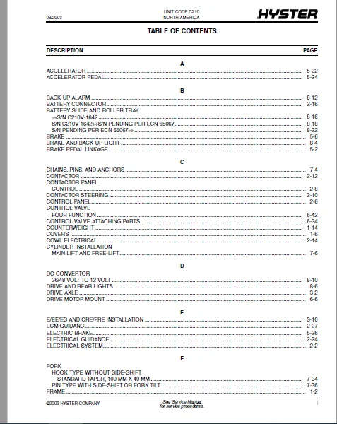
TABLE OF CONTENTS:
Hyster ELECTRIC N30XMH2 (C210) Parts Manual 1475781 – PDF DOWNLOAD
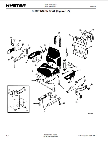
toc.........................................................  1
	1 FRAME................................................. 17
		FRAME (Figure 1-1).................................. 20
		COVERS (Figure 1-2)................................. 24
		HOOD (Figure 1-3)................................... 26
		OVERHEAD GUARD (Figure 1-4)......................... 30
		COUNTERWEIGHT (Figure 1-5).......................... 32
		NON-SUSPENSION SEAT (Figure 1-6).................... 34
		SUSPENSION SEAT (Figure 1-7)........................ 36
		FULL SUSPENSION SEAT (Figure 1-8)................... 40
		FULL SUSPENSION SEAT (Figure 1-9)................... 42
		LABELS (Figure 1-10)................................ 44
	2 ELECTRICAL SYSTEM..................................... 47
		ELECTRICAL SYSTEM (Figure 2-1)...................... 50
		CONTROL PANEL (Figure 2-2).......................... 54
		CONTACTOR PANEL (Figure 2-3)........................ 56
		CONTACTOR STEERING (Figure 2-4)..................... 58
		CONTACTOR (Figure 2-5).............................. 60
		COWL ELECTRICAL (Figure 2-6)........................ 62
		BATTERY CONNECTOR (Figure 2-7)...................... 64
		WIRE HARNESS (Figure 2-8)........................... 66
		WIRE HARNESS (Figure 2-9)........................... 67
		WIRE HARNESS (Figure 2-10).......................... 68
		WIRE HARNESS (Figure 2-11).......................... 70
		ELECTRICAL GUIDANCE (Figure 2-12)................... 72
		LOAD END SENSOR (Figure 2-13)....................... 74
		ECM GUIDANCE (Figure 2-14).......................... 75
		GUIDANCE SWITCH AND SIGNAL (Figure 2-15)............ 76
	3 DRIVE UNIT............................................ 77
		DRIVE AXLE (Figure 3-1)............................. 80
		TRANSMISSION AND DIFFERENTIAL (Figure 3-2).......... 84
		E/EE/ES AND CRE/FRE INSTALLATION (Figure 3-3)....... 88
		TRACTION MOTOR (Figure 3-4)......................... 90
		TRACTION MOTOR (Figure 3-5)......................... 92
	4 STEERING SYSTEM....................................... 95
		STEERING POD (Figure 4-1)........................... 98
		SHIFT LEVER (Figure 4-2)............................100
		STEERING CONTROL UNIT (Figure 4-3)..................102
		STEERING HYDRAULIC (Figure 4-4).....................104
		STEERING CYLINDER (Figure 4-5)......................106
		GEAR PUMP (Figure 4-6)..............................107
		GEAR PUMP (Figure 4-7)..............................108
		STEERING MOTOR (Figure 4-8).........................110
		STEERING MOTOR (Figure 4-9).........................112
		STEERING MOTOR (Figure 4-10)........................114
		STEERING MOTOR (Figure 4-11)........................116
		STEERING AXLE (Figure 4-12).........................118
		STEERING AXLE (Figure 4-13).........................122
		STEERING CONTROL UNIT (Figure 4-14).................126
		STEERING AXLE GUIDANCE (Figure 4-15)................128
	5 BRAKE/ACCELERATOR SYSTEM..............................131
		BRAKE PEDAL LINKAGE (Figure 5-1)....................134
		MASTER CYLINDER (Figure 5-2)........................136
		BRAKE (Figure 5-3)..................................138
		PARK BRAKE (Figure 5-4).............................140
		PARK BRAKE LINKAGE (Figure 5-5).....................144
		PARK BRAKE LINKAGE (Figure 5-6).....................148
		PARK BRAKE (Figure 5-7).............................150
		PARK BRAKE (Figure 5-8).............................152
		ACCELERATOR (Figure 5-9)............................154
		ACCELERATOR PEDAL (Figure 5-10).....................156
		ELECTRIC BRAKE (Figure 5-11)........................158
	6 HYDRAULIC SYSTEM......................................159
		HYDRAULIC (Figure 6-1)..............................162
		DRIVE MOTOR MOUNT (Figure 6-2)......................166
		HYDRAULIC PUMP (Figure 6-3).........................168
		HYDRAULIC PUMP (Figure 6-4).........................170
		HYDRAULIC PUMP (Figure 6-5).........................172
		HYDRAULIC PUMP (Figure 6-6).........................174
		HYDRAULIC PUMP (Figure 6-7).........................176
		HYDRAULIC PUMP (Figure 6-8).........................178
		HYDRAULIC PUMP (Figure 6-9).........................180
		HYDRAULIC MOTOR (Figure 6-10).......................182
		HYDRAULIC MOTOR (Figure 6-11).......................184
		HYDRAULIC MOTOR (Figure 6-12).......................186
		HYDRAULIC MOTOR (Figure 6-13).......................188
		HYDRAULIC MOTOR (Figure 6-14).......................190
		HYDRAULIC MOTOR (Figure 6-15).......................192
		CONTROL VALVE ATTACHING PARTS (Figure 6-16).........194
		HAND LEVER (Figure 6-17)............................198
		HAND LEVER (Figure 6-18)............................200
		CONTROL VALVE (Figure 6-19).........................202
		HYDRAULIC TANK (Figure 6-20)........................206
		GUIDANCE HYDRAULICS (Figure 6-21)...................208
	7 MAST-THREE STAGE FULL FREE-LIFT.......................211
		OUTER, INTERMEDIATE, AND INNER MAST (Figure 7-1)....214
		CHAINS, PINS, AND ANCHORS (Figure 7-2)..............216
		CYLINDER INSTALLATION (Figure 7-3)..................218
		LIFT HYDRAULICS (Figure 7-4)........................220
		FREE-LIFT CYLINDER (Figure 7-5).....................222
		MAIN LIFT CYLINDER (Figure 7-6).....................224
		MAST MOUNTING (Figure 7-7)..........................226
		TRAVERSE BOOM (Figure 7-8)..........................228
		TRAVERSE FRAME (Figure 7-9).........................232
		TRAVERSE FRAME (Figure 7-10)........................236
		TRAVERSE CYLINDER (Figure 7-11).....................238
		SIDE-SHIFT CYLINDER (Figure 7-12)...................240
		HEADER HOSE (Figure 7-13)...........................242
		HOSE REEL (Figure 7-14).............................244
		FORK (Figure 7-15)..................................246
		FORK (Figure 7-16)..................................248
	8 OPTIONS...............................................249
		TIRE AND WHEEL (Figure 8-1).........................252
		BRAKE AND BACK-UP LIGHT (Figure 8-2)................254
		DRIVE AND REAR LIGHTS (Figure 8-3)..................256
		STROBE LIGHT (Figure 8-4)...........................258
		DC CONVERTOR (Figure 8-5)...........................260
		BACK-UP ALARM (Figure 8-6)..........................262
		WIRE HARNESS (Figure 8-7)...........................263
		WIRE HARNESS (Figure 8-8)...........................264
		GUIDE ROLLER (Figure 8-9)...........................265
		BATTERY SLIDE AND ROLLER TRAY (Figure 8-10).........266
		BATTERY SLIDE AND ROLLER TRAY (Figure 8-11).........268
		BATTERY SLIDE AND ROLLER TRAY (Figure 8-12).........272
		WIRE HARNESS (Figure 8-13)..........................274
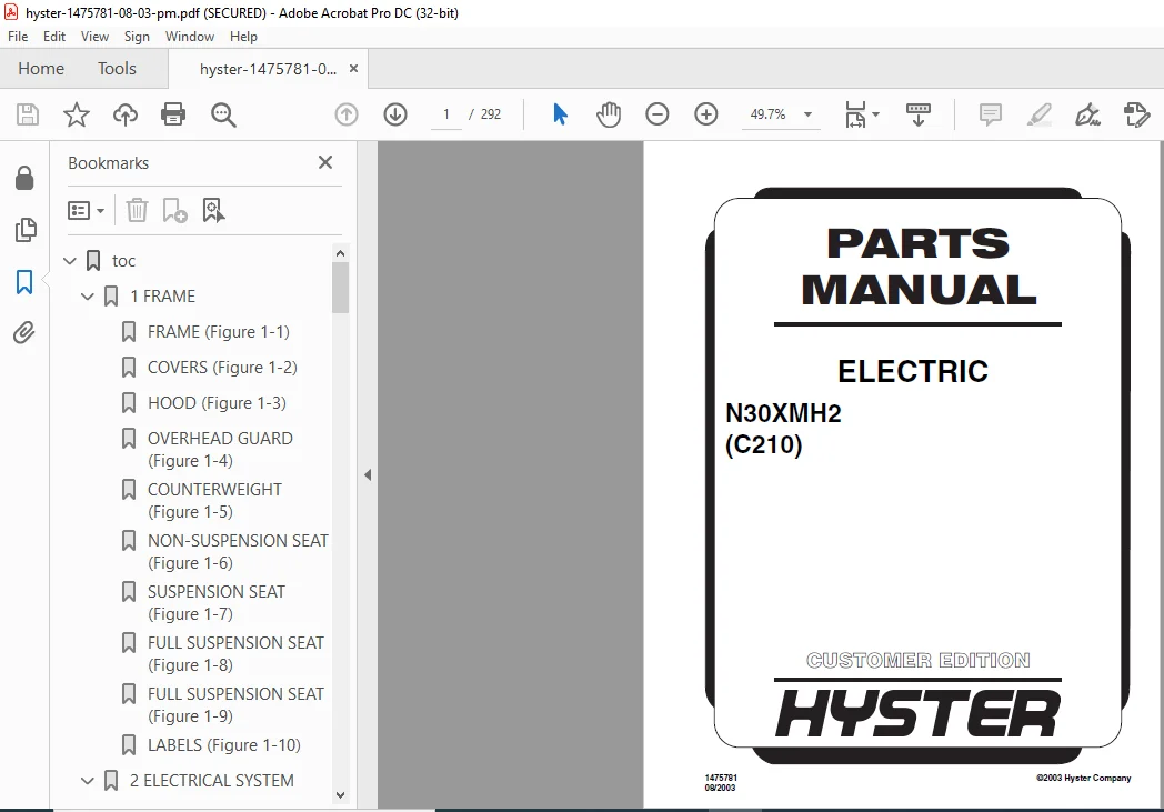
IMAGES PREVIEW OF THE MANUAL:
HYSTER ELECTRIC N30XMH2 (C210) PARTS MANUAL 1475781 – PDF DOWNLOAD:
PLEASE NOTE:
- This is the same manual used by the dealers to diagnose and troubleshoot your vehicle
- You will be directed to the download page as soon as the purchase is completed. The whole payment and downloading process will take anywhere between 2-5 minutes
- Need any other service / repair / parts manual, please feel free to contact [email protected] . We still have 50,000 manuals unlisted
S.V


Alberto Marlon –
Found what I was looking for and got a bit of discount. So far looks very good. Second time i’m buying from heydownloads.