Trusted Business
Verified & Licensed
Virus Free Files
100% Safe Downloads
Secure Payment
SSL Protected
Instant Delivery
Available Immediately
Sale!

Hyster ELECTRIC N30XMXDR3 N45XMXR3 (B264) Parts Manual – PDF DOWNLOAD
Original price was: $98.95.$29.95Current price is: $29.95.
Hyster ELECTRIC N30XMXDR3 N45XMXR3 (B264) Parts Manual – PDF DOWNLOAD
Instant PDF Download
Available immediately
Save to Your Device
Download & keep forever
Antivirus Scanned
100% virus-free
Trusted Worldwide
175,000+ customers
Description
Hyster ELECTRIC N30XMXDR3 N45XMXR3 (B264) Parts Manual – PDF DOWNLOAD
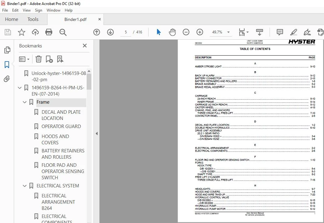
TABLE OF CONTENTS:
Hyster ELECTRIC N30XMXDR3 N45XMXR3 (B264) Parts Manual – PDF DOWNLOAD
Unlock-hyster-1496159-08-02-pm...............................................  1
1496159-B264-H-PM-US-EN-(07-2014)............................................183
	Frame....................................................................197
		DECAL AND PLATE LOCATION.............................................200
		OPERATOR GUARD.......................................................202
		HOODS AND COVERS.....................................................204
		BATTERY RETAINERS AND ROLLERS........................................206
		FLOOR PAD AND OPERATOR SENSING SWITCH................................208
	ELECTRICAL SYSTEM........................................................209
		ELECTRICAL ARRANGEMENT B264..........................................212
		ELECTRICAL COMPONENTS................................................216
		ELECTRICAL COMPONENTS................................................218
		CONTACTOR PANEL......................................................220
		MULTI-FUNCTION CONTROL HANDLE ASSEMBLY...............................222
		MULTI-FUNCTION CONTROL HANDLE ASSEMBLY...............................224
		MULTI-FUNCTION CONTROL HANDLE B264...................................226
		POWER STEER CONTACTOR................................................228
		TRACTION CONTACTOR...................................................229
		LIFT CONTACTOR.......................................................230
		WIRE HARNESS HYDRAULIC CONTROL.......................................232
		BATTERY CONNECTOR....................................................234
	DRIVE UNIT...............................................................235
		DRIVE UNIT ASSEMBLY..................................................238
		MASTER DRIVE UNIT....................................................240
		MASTER DRIVE UNIT....................................................244
		DRIVE UNIT ASSEMBLY..................................................246
		DRIVE UNIT ASSEMBLY..................................................248
		DRIVE UNIT ASSEMBLY..................................................250
		TRACTION MOTOR.......................................................252
		TRACTION MOTOR.......................................................254
	STEERING SYSTEM..........................................................257
		POWER STEER ARRANGEMENT..............................................260
		POWER STEER ARANGEMENT...............................................262
		HYDRAULIC STEER MOTOR................................................264
		HYDRAULIC STEER MOTOR................................................266
		STEER CONTROL UNIT...................................................268
		STEER AND AUXILIARY PUMP AND MOTOR...................................270
		STEER AND AUXILIARY MOTOR 36 VOLT - "E" CONSTRUCTION ................272
		STEER AND AUXILIARY PUMP.............................................274
		CASTER WHEEL.........................................................276
	BRAKE/ACCELERATOR SYSTEM.................................................279
		BRAKE ASSEMBLY.......................................................282
		BRAKE PEDAL ASSEMBLY.................................................283
		TANDEM LOAD WHEEL....................................................284
	HYDRAULIC SYSTEM.........................................................287
		HYDRAULIC SYSTEM.....................................................290
		HYDRAULIC TANK ASSEMBLY..............................................294
		SINGLE REACH HYDRAULICS..............................................296
		DOUBLE REACH HYDRAULICS..............................................298
		HYDRAULIC PUMP MOTOR.................................................300
		HYDRAULIC PUMP.......................................................302
		HYDRAULIC CONTROL VALVE..............................................304
		HYDRAULIC CONTROL VALVE..............................................306
		REACH CONTROL VALVE..................................................308
	Mast-Three Stage Full Free-Lift..........................................309
		INNER, INTERMEDIATE, AND OUTER MAST THREE STAGE FULL FREE-LIFT.......312
		MAST ATTACHING PARTS.................................................316
		HOSE ARRANGEMENT B585 MAST...........................................318
		HOSE ARRANGEMENT C570 MAST...........................................320
		CHAINS, PINS, AND ANCHORS THREE STAGE FULL FREE-LIFT.................324
		MAIN LIFT CYLINDER THREE STAGE FULL FREE-LIFT  (→ 8/2002) ...........327
		MAIN LIFT CYLINDER THREE STAGE FULL FREE-LIFT  (8/2002 →) ...........330
		MAIN CYLINDER ARRANGEMENT THREE STAGE FULL FREE-LIFT  (8/2002 →) ....334
		MAIN CYLINDER ARRANGEMENT THREE STAGE FULL FREE-LIFT  (→ 8/2002) ....336
		FREE-LIFT CYLINDER THREE STAGE FULL FREE-LIFT........................338
		LIFT LIMIT SWITCH THREE STAGE FULL FREE-LIFT.........................342
		HOSE AND WIRE TAKE-UP................................................344
	Carriage.................................................................347
		FORKS SHAFT TYPE.....................................................350
		FORKS HOOK TYPE  (→ 10/2001) ........................................352
		FORKS HOOK TYPE  (10/2001 →) ........................................354
		LOAD BACKREST........................................................355
		INTEGRAL TILT ASSEMBLY...............................................356
		INTEGRAL TILT ASSEMBLY WITH SIDE-SHIFT...............................358
		SCISSOR ASSEMBLY 24 IN. REACH........................................362
		SCISSOR ASSEMBLY 42 INCH REACH.......................................364
		CARRIAGE INNER FRAME.................................................368
		REACH CYLINDER 24 IN. REACH..........................................371
		REACH CYLINDER 42 IN. REACH  (→ S/N B264N01716B) ....................372
		REACH CYLINDER 42 IN. REACH  (S/N B264N01717B →) ....................373
	OPTIONS..................................................................375
		PMC HEATER...........................................................378
		SHELF HEIGHT SELECTOR................................................380
		LINEAR SENSOR........................................................382
		PMC HEATER...........................................................384
		REAR WORKING LIGHT...................................................386
		HEADLIGHTS...........................................................387
		LIGHT AND FAN ASSEMBLY WITHOUT SPOTLIGHT.............................388
		AMBER STROBE LIGHT...................................................390
		BACK-UP ALARM........................................................392
		BATTERY STAND AND PULLER.............................................394
		DIAGNOSTIC HANDSET...................................................396
	FIELD CONVERSION KITS....................................................397
		MISCELLANEOUS CONVERSION KITS........................................400
	NUMERICAL INDEX..........................................................401
DESCRIPTION:
Hyster ELECTRIC N30XMXDR3 N45XMXR3 (B264) Parts Manual – PDF DOWNLOAD
HOW TO USE THE ILLUSTRATED PARTS MANUAL :
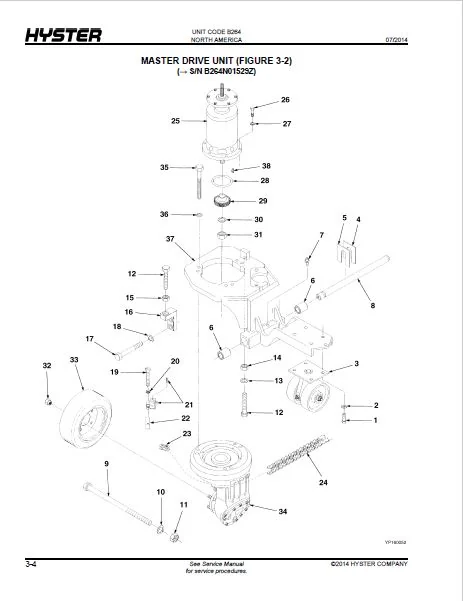
- This parts manual describes and illustrates assemblies, subassemblies, and detail parts needed for service replacement.
- The different constructions are indicated by keys and footnotes. The callouts correspond to descriptions found on the next page.
HOW TO FIND THE DESIRED PART NUMBER
WHEN THE PART NUMBER AND THE NEXT HIGHER ASSEMBLY IS NOT KNOWN:
1. Determine the function and application of the part required. Turn to the Sections Page. Choose the general area of reference most likely to include the part.
WHEN THE PART NUMBER AND THE NEXT HIGHER ASSEMBLY IS NOT KNOWN:
1. Determine the function and application of the part required. Turn to the Sections Page. Choose the general area of reference most likely to include the part.
2. Turn to the section you chose. Use the Section Table of Contents to determine the assembly which would normally contain the part required. Then locate the part on the assembly breakdown page.
WHEN THE PART NUMBER IS NOT KNOWN AND THE NEXT HIGHER ASSEMBLY IS KNOWN:
3. Determine the assembly the required part is used on. Turn to the Table of Contents (Page i).
WHEN THE PART NUMBER IS NOT KNOWN AND THE NEXT HIGHER ASSEMBLY IS KNOWN:
3. Determine the assembly the required part is used on. Turn to the Table of Contents (Page i).
4. Locate the assembly the required part is used on and turn to the page indicated for that assembly. Then locate the part on the assembly breakdown page.
WHEN THE PART NUMBER IS KNOWN:
5. Use the Numerical Index (Page 10-1) to find the part number. Turn to the page listed and locate the part as indicated by the item number.
GENERAL:
The assembly breakdowns include part numbers, descriptions, quantities required, keys and footnotes to help in selecting correct parts.
WHEN THE PART NUMBER IS KNOWN:
5. Use the Numerical Index (Page 10-1) to find the part number. Turn to the page listed and locate the part as indicated by the item number.
GENERAL:
The assembly breakdowns include part numbers, descriptions, quantities required, keys and footnotes to help in selecting correct parts.
6. Parts Supersession Information. Part numbers that have this history will be displayed in the parts list in the order that they were superseded (from oldest to newest). The superseded part numbers will be shown with a line through them.
- Five periods in the PART NO. column (. . . . .) indicate that the part is either Not Serviced Separately or there is a reference to another figure. A figure reference is denoted by a pointing hand followed by a figure number in the DESCRIPTION column (FFigure 10)
7. Keys are used to show two or more similar assemblies, RH and LH assembly parts, etc. Select the appropriate key, “A”, “B”, “C”, “D”, or “E” and the corresponding quantity column to find the required parts. Two periods in the QTY column (..) indicate that the part is not used for that assembly.
HYSTER ELECTRIC N30XMXDR3 N45XMXR3 (B264) PARTS MANUAL – PDF DOWNLOAD:
IMAGES PREVIEW OF THE MANUAL:
PLEASE NOTE:
- This is the same manual used by the DEALERSHIPS to SERVICE your vehicle.
- The manual can be all yours – Once payment is complete, you will be taken to the download page from where you can download the manual. All in 2-5 minutes time!!
- Need any other service / repair / parts manual, please feel free to contact us at heydownloadss @gmail.com . We may surprise you with a nice offer
S.V