Trusted Business
Verified & Licensed
Virus Free Files
100% Safe Downloads
Secure Payment
SSL Protected
Instant Delivery
Available Immediately
Sale!


Hyster Forklift S30 50E, S60ES service manual – PDF DOWNLOAD
Original price was: $92.95.$32.95Current price is: $32.95.
Hyster Forklift S30 50E, S60ES service manual
Instant PDF Download
Available immediately
Save to Your Device
Download & keep forever
Antivirus Scanned
100% virus-free
Trusted Worldwide
175,000+ customers
Description
Hyster Forklift S30 50E, S60ES service manual
File Details:
Hyster Forklift S30 50E, S60ES service manual
Language : English
Pages : 355
Size : 9.70 MB
Downloadable : Yes
Format : PDF
HYSTER FORKLIFT S30 50E, S60ES SERVICE MANUAL – PDF DOWNLOAD:
Image Preview:
Description:
Hyster Forklift S30 50E, S60ES service manual
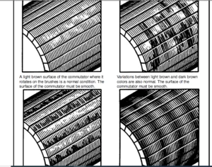
- NOTE: For this SRM section, the alternators are in two groups, Type A and Type B. The two types are very similar, but the Type A alternators have a set of three diodes (diode set) as well as the diode bridge. The Type B alternator has zener diodes as part of the diodes in the diode bridge.
- This alternator does not have a diode set, but does have an additional fan inside the rear housing. The basic operation of both types is very similar. The alternator generates an alternating current when the engine is running. The alternator is either ON or OFF. The alternator generates maximum current when it is ON and no current when it is OFF. The regulator switches the alternator between ON and OFF to get the average current needed to charge the battery.
- Alternator output is directly changed by engine speed and rotor field current. The alternating current is changed to a direct current by the diode bridge inside the alternator.
Table of Contents:
Hyster Forklift S30 50E, S60ES service manual
INTRODUCTION.............................................................................................  1
	GENERAL..............................................................................................  1
	DESCRIPTION..........................................................................................  1
REPAIRS..................................................................................................  3
	GENERAL..............................................................................................  3
	REMOVAL AND DISASSEMBLY (Type A).....................................................................  3
	CLEANING.............................................................................................  3
	ASSEMBLY (Type A)....................................................................................  4
	REMOVAL AND DISAASSEMBLY (Type B)....................................................................  6
	CLEANING.............................................................................................  8
	ASSEMBLY (Type B)....................................................................................  8
	INSTALLATION (Type A and Type B).....................................................................  9
CHECKS AND ADJUSTMENTS...................................................................................  9
	GENERAL..............................................................................................  9
	CHECK THE ALTERNATOR FOR LOW OUTPUT (Type A or Type B)............................................... 10
	CHECK THE ALTERNATOR FOR HIGH OUTPUT (Type A or Type B).............................................. 11
	CHECK THE CIRCUIT FOR THE BRUSHES.................................................................... 13
		Delco Alternators................................................................................ 13
		Motorola Alternators............................................................................. 13
	CHECK THE DIODES..................................................................................... 13
	CHECK THE DIODE BRIDGE............................................................................... 13
		Delco and Leece–Neville Alternators.............................................................. 13
		Motorola Alternators............................................................................. 13
	CHECK THE FIELD WINDING FOR THE ROTOR................................................................ 14
	CHECK THE WINDINGS IN THE STATOR..................................................................... 14
	CHECK THE VOLTAGE REGULATOR.......................................................................... 15
TROUBLESHOOTING.......................................................................................... 15
INTRODUCTION............................................................................................. 16
	GENERAL.............................................................................................. 16
	DESCRIPTION AND OPERATION............................................................................ 16
REPAIRS.................................................................................................. 20
	CLEANING PROCEDURES.................................................................................. 20
	REMOVAL AND DISASSEMBLY.............................................................................. 20
	INSPECTION........................................................................................... 21
	ASSEMBLY............................................................................................. 22
CHECKS AND ADJUSTMENTS................................................................................... 24
	ADJUSTING THE SERVICE BRAKES......................................................................... 24
	ADJUSTING THE PARKING BRAKE.......................................................................... 24
	REMOVING THE AIR FROM THE BRAKE SYSTEM............................................................... 24
	ADJUSTING THE SERVICE BRAKE PEDAL.................................................................... 25
TROUBLESHOOTING.......................................................................................... 26
INTRODUCTION............................................................................................. 31
	GENERAL.............................................................................................. 31
	DESCRIPTION.......................................................................................... 31
REPAIRS.................................................................................................. 34
	FAN ASSEMBLY......................................................................................... 34
		Removal (S30–120E)............................................................................... 34
		Removal (H60–110E)............................................................................... 34
		Disassembly (S30–120E)........................................................................... 34
		Disassembly (H60–110E)........................................................................... 35
		Assembly (Both Series)........................................................................... 35
		Fan Belt Adjustment.............................................................................. 38
		Installation..................................................................................... 38
	RADIATOR............................................................................................. 39
		Removal.......................................................................................... 39
		Installation..................................................................................... 39
		Cleaning and Inspection.......................................................................... 40
TROUBLESHOOTING.......................................................................................... 41
INTRODUCTION............................................................................................. 48
	General.............................................................................................. 48
	Description.......................................................................................... 48
REPAIRS.................................................................................................. 49
	Removal.............................................................................................. 49
	Installation......................................................................................... 50
	Axle Housing For S30-100E And S40-50F Lift Trucks.................................................... 51
	Wheels And Tires..................................................................................... 53
TROUBLESHOOTING.......................................................................................... 55
SPECIFICATIONS........................................................................................... 56
HIGH ENERGY IGNITION (HEI)............................................................................... 58
	DESCRIPTION.......................................................................................... 58
REPAIRS.................................................................................................. 60
	DISTRIBUTOR.......................................................................................... 60
		Removal.......................................................................................... 60
		Disassembly...................................................................................... 60
		Assembly......................................................................................... 65
	INSTALLATION, IF THE CRANKSHAFT WAS NOT ROTATED WHEN DISTRIBUTOR WAS REMOVED......................... 66
	NSTALLATION, IF THE CRANKSHAFT WAS ROTATED WHEN THE DISTRIBUTOR WAS REMOVED.......................... 67
	IGNITION COIL........................................................................................ 67
		Removal, Some 4 And 6 Cylinder Models............................................................ 67
		Installation, Some 4 And 6 Cylinder Models....................................................... 68
		Removal, V8, Some 4 And 6 Cylinder Models........................................................ 68
		Installation, V8, Some 4 And 6 Cylinder Models................................................... 69
	ELECTRONIC MODULE.................................................................................... 70
		Removal.......................................................................................... 70
		Installation..................................................................................... 70
	SENSING COIL......................................................................................... 71
		Removal.......................................................................................... 71
		Installation..................................................................................... 71
	SPARK PLUGS.......................................................................................... 71
		Removal.......................................................................................... 71
		Installation..................................................................................... 72
	CHECKS AND ADJUSTMENTS............................................................................... 72
		Visual Checks.................................................................................... 72
		Check The High Voltage Wires..................................................................... 72
		Checking The Ignition Coil....................................................................... 72
		Coil In Distributor Cap Design................................................................... 72
		Separate Coil Design............................................................................. 73
		Checking The Sensing Coil........................................................................ 73
		Check The Electronic Module...................................................................... 74
		Ignition Timing Adjustment....................................................................... 74
		Ignition System, GM V8-366 (6-litre)............................................................. 75
		Ignition Timing and Idle Speed Adjustment, GM V6-LPG (4.3-litre)................................. 75
SPECIFICATIONS........................................................................................... 75
TROUBLESHOOTING.......................................................................................... 76
ELECTRICAL WARNING DEVICES............................................................................... 77
	GENERAL.............................................................................................. 77
	DESCRIPTION.......................................................................................... 77
		Operator Controlled Horns........................................................................ 77
		System Warning Lights, Buzzers and Bells......................................................... 77
		Reverse Warning Horns............................................................................ 78
		Warning Lights................................................................................... 78
	REPLACEMENT.......................................................................................... 79
		General.......................................................................................... 79
		Replacing Horns or Bells......................................................................... 79
		Replacing Horn Relay or Buzzer................................................................... 79
		Replacing Warning Lights......................................................................... 79
		Light Assemblies................................................................................. 80
		Replacing Flashing Units......................................................................... 80
INTRODUCTION............................................................................................. 81
	General.............................................................................................. 81
	Description.......................................................................................... 81
	Operation............................................................................................ 81
		Flow Regulator Valve............................................................................. 82
		Steering Relief Valve............................................................................ 83
		Relief Valve for Cold Oil........................................................................ 84
REPAIRS.................................................................................................. 84
	Removal.............................................................................................. 84
	Disassembly.......................................................................................... 84
	Cleaning and Inspection.............................................................................. 84
	Assembly and Installation............................................................................ 84
CHECKS AND ADJUSTMENTS................................................................................... 85
	Removing air from the Hydraulic System............................................................... 85
	Adjusting the Setting of the Relief Valve............................................................ 85
INTRODUCTION............................................................................................. 87
	General.............................................................................................. 87
	Description.......................................................................................... 87
DISASSEMBLY AND ASSEMBLY................................................................................. 88
	Counterweight........................................................................................ 88
	Hood and Seat........................................................................................ 90
	Operator Restraint System............................................................................ 91
	Exhaust System....................................................................................... 92
	Overhead Guard....................................................................................... 92
	Engine (Removal and Installation).................................................................... 95
REPAIRS.................................................................................................. 97
	Fuel and Hydraulic Tanks............................................................................. 97
	Decal Replacement.................................................................................... 98
INTRODUCTION.............................................................................................100
	GENERAL..............................................................................................100
	DESCRIPTION..........................................................................................101
	REMOVAL AND INSTALLATION OF THE ENGINE...............................................................101
	CYLINDER HEAD AND MECHANISM..........................................................................101
		Cylinder Head, Removal...........................................................................101
		Cylinder Head, Disassembly.......................................................................102
		Cleaning And Inspection..........................................................................103
		Valve And Valve Seats............................................................................104
		Studs For The Rocker Arms........................................................................104
		Hydraulic Valve Lifters, Replacement.............................................................104
		Hydraulic Valve Lifters, Cleaning And Inspection.................................................105
		Cylinder Head, Assembly..........................................................................105
		Cylinder Head, Installation......................................................................105
		Rocker Arm Cover, Installation...................................................................106
	TIMING GEAR COVER....................................................................................107
		Removal..........................................................................................107
		Installation.....................................................................................107
	CAMSHAFT.............................................................................................108
		Removal..........................................................................................108
		Inspection.......................................................................................109
		Camshaft Bearings, Removal.......................................................................109
		Camshaft Bearings, Installation..................................................................109
	DISTRIBUTOR..........................................................................................110
		Removal..........................................................................................110
		Installation.....................................................................................110
	LUBRICATION SYSTEM...................................................................................111
		Oil Sump, Removal................................................................................111
		Oil Sump, Installation...........................................................................111
		Oil Pump, Removal................................................................................111
		Oil Pump, Disassembly and Repair.................................................................111
		Oil Pump, Assembly...............................................................................112
		Oil Pump, Installation...........................................................................112
	PISTON AND CONNECTING ROD ASSEMBLIES.................................................................112
		Connecting Rod Bearings, Replacement.............................................................112
		Piston And Connecting Rod Assemblies, Removal....................................................113
		Disassembly......................................................................................114
		Piston, Cleaning And Inspection..................................................................114
		Cylinder Bores, Inspection And Repair............................................................114
		Piston Rings.....................................................................................115
		Assembly.........................................................................................116
		Piston And Connecting Rod Assemblies, Installation...............................................116
	CRANKSHAFT...........................................................................................117
		Main Bearings, Replacement.......................................................................117
		Oil Seal For The Rear Main Bearing, Replacement (GM 4-181 and 3.0L Only).........................118
		Oil Seal For The Rear Main Bearing, Replacement (Engines That Have A Two-Piece Oil Seal).........118
		Crankshaft, Removal..............................................................................119
		Inspection and Repair............................................................................120
		How To Check The Clearance Between The Main Bearings And Their Journals..........................120
		Installation.....................................................................................121
	FLYWHEEL AND FLYWHEEL HOUSING........................................................................122
		Flywheel, Removal................................................................................122
		Ring Gear, Replacement...........................................................................123
		Flywheel, Installation...........................................................................123
	COOLING SYSTEM.......................................................................................123
		Coolant Pump.....................................................................................123
		Fan Drive........................................................................................124
		Viscous Fan Drive................................................................................124
ENGINE SPECIFICATIONS....................................................................................125
	ENGINE DATA..........................................................................................125
	CYLINDER HEAD........................................................................................125
	HYDRAULIC VALVE LIFTER...............................................................................126
	CAMSHAFT.............................................................................................126
	PISTONS..............................................................................................126
	CYLINDER BORE........................................................................................127
	CRANKSHAFT...........................................................................................127
	CONNECTING RODS......................................................................................127
	COOLING SYSTEM.......................................................................................128
	LUBRICATION SYSTEM...................................................................................128
TORQUE SPECIFICATIONS....................................................................................128
HIGH ENERGY IGNITION (HEI)...............................................................................131
	DESCRIPTION..........................................................................................131
REPAIRS..................................................................................................133
	DISTRIBUTOR..........................................................................................133
		Removal..........................................................................................133
		Disassembly......................................................................................133
		Assembly.........................................................................................138
	INSTALLATION, IF THE CRANKSHAFT WAS NOT ROTATED WHEN DISTRIBUTOR WAS REMOVED.........................139
	NSTALLATION, IF THE CRANKSHAFT WAS ROTATED WHEN THE DISTRIBUTOR WAS REMOVED..........................140
	IGNITION COIL........................................................................................140
		Removal, Some 4 And 6 Cylinder Models............................................................140
		Installation, Some 4 And 6 Cylinder Models.......................................................141
		Removal, V8, Some 4 And 6 Cylinder Models........................................................141
		Installation, V8, Some 4 And 6 Cylinder Models...................................................142
	ELECTRONIC MODULE....................................................................................143
		Removal..........................................................................................143
		Installation.....................................................................................143
	SENSING COIL.........................................................................................144
		Removal..........................................................................................144
		Installation.....................................................................................144
	SPARK PLUGS..........................................................................................144
		Removal..........................................................................................144
		Installation.....................................................................................145
	CHECKS AND ADJUSTMENTS...............................................................................145
		Visual Checks....................................................................................145
		Check The High Voltage Wires.....................................................................145
		Checking The Ignition Coil.......................................................................145
		Coil In Distributor Cap Design...................................................................145
		Separate Coil Design.............................................................................146
		Checking The Sensing Coil........................................................................146
		Check The Electronic Module......................................................................147
		Ignition Timing Adjustment.......................................................................147
		Ignition System, GM V8-366 (6-litre).............................................................148
		Ignition Timing and Idle Speed Adjustment, GM V6-LPG (4.3-litre).................................148
SPECIFICATIONS...........................................................................................148
TROUBLESHOOTING..........................................................................................149
INTRODUCTION.............................................................................................150
	DESCRIPTION..........................................................................................150
	OPERATION............................................................................................150
		Flow Control Valve...............................................................................152
		Relief Valve.....................................................................................152
REPAIRS..................................................................................................153
	REMOVAL..............................................................................................153
	DISASSEMBLY..........................................................................................153
	CLEANING.............................................................................................155
	INSPECTION...........................................................................................155
	ASSEMBLY.............................................................................................156
	INSTALLATION.........................................................................................157
CHECKS AND ADUSTMENTS....................................................................................158
	CHECK THE OUTPUT OF THE PUMP.........................................................................158
	CHECK FOR AIR IN THE HYDRAULIC SYSTEM................................................................158
TROUBLESHOOTING..........................................................................................160
INTRODUCTION.............................................................................................163
	GENERAL..............................................................................................163
	DESCRIPTION..........................................................................................163
REPAIRS..................................................................................................163
	REMOVAL AND DISASSEMBLY..............................................................................163
	CLEANING.............................................................................................165
	INSPECTION...........................................................................................165
	ASSEMBLY AND INSTALLATION............................................................................165
TROUBLESHOOTING..........................................................................................167
	GENERAL..............................................................................................167
INTRODUCTION.............................................................................................168
	GENERAL..............................................................................................168
DESCRIPTION..............................................................................................168
	GENERAL..............................................................................................168
	STEERING COLUMN GAUGES, METERS AND INDICATORS........................................................171
	LED DISPLAY PANEL....................................................................................171
		Battery Discharge Indicators.....................................................................171
		Brush Wear Indicators............................................................................172
		Motor Temperature Indicators.....................................................................173
	"LX" SERIES DISPLAY PANEL............................................................................174
		Hourmeter Functions..............................................................................175
		Battery Indicator Function.......................................................................175
		Status Code Function.............................................................................175
	"ZX" SERIES DISPLAY PANELS...........................................................................175
		Display Panel....................................................................................176
		Basic Display Panels.............................................................................176
		Performance Display..............................................................................178
		Brush Wear Indicators............................................................................181
CHECKS AND ADJUSTMENTS...................................................................................181
	GENERAL..............................................................................................181
REPLACEMENT..............................................................................................182
	GENERAL..............................................................................................182
	METER REPLACEMENT....................................................................................182
	SENDER REPLACEMENT...................................................................................183
		Fuel Level Sender................................................................................183
		Pressure And Temperature Sender..................................................................183
	I.T.W. DISPLAY PANEL.................................................................................184
		Removal..........................................................................................184
	DISPLAY PANELS FOR THE EV - 100/200ZX MOTOR CONTROLLERS, COLUMN MOUNT................................185
		Removal..........................................................................................185
		Replacing Display Panel Assembly.................................................................185
		Indicator LEDs...................................................................................185
		Battery Indicators...............................................................................185
		Digital Display (Performance Disply Panel Only)..................................................185
		Status Code Or Performance Level Switches And Indicator LEDs (Performance Display Panel Only)....185
		Replacing Parts Of The Basic Display Panel.......................................................186
		Replacing Parts Of The Performance Display Panel.................................................188
	DISPLAY PANELS FOR THE EV-100/200ZX MOTOR CONTROLLERS, DASH MOUNT....................................188
		Removal And Replacement..........................................................................188
SPECIFICATIONS...........................................................................................189
TROUBLESHOOTING..........................................................................................190
SAFETY PROCEDURES WHEN WORKING NEAR THE MAST.............................................................191
	SAFETY PROCEDURES WHEN WORKING NEAR THE MAST.........................................................191
LIFT CYLINDERS...........................................................................................194
	GENERAL..............................................................................................194
	DESCRIPTION..........................................................................................194
		Lowering Control Valve...........................................................................194
		Cylinders (General)..............................................................................197
		Cylinders (H520-620B,H700-800A)..................................................................199
		Cylinders (H360-460B)............................................................................200
		Cylinders (Two-Speed)............................................................................200
REPAIRS..................................................................................................201
	REMOVAL OF THE LIFT CYLINDER WITHOUT REMOVING THE MAST...............................................201
		Standard Masts with the Main Lift Cylinder Fastened to the Crossmember of the Inner Mast.........201
		Standard and Full Free-Lift Masts with the Lift Cylinder to a Crosshead..........................205
		Masts that have Two Cylinders, A Main Lift Cylinder  and a Free-Lift Cylinder....................203
	DISASSEMBLY..........................................................................................203
	ASSEMBLY.............................................................................................205
	INSTALLATION OF THE LIFT CYLINDER IN THE MAST........................................................205
		Standard Masts with the Main Lift Cylinder Fastened to the Crossmember of the Inner Mast.........205
		Standard and Full-Free-Lift Masts with the Lift Cylinder Fastened to a Crosshead.................205
	CHEVRON PACKING......................................................................................206
LIFT CYLINDERS FOR VISTA MASTS...........................................................................209
	DESCRIPTION..........................................................................................209
		Lowering Control Valve...........................................................................211
	REMOVAL..............................................................................................212
	DISASSEMBLY..........................................................................................212
	ASSEMBLY.............................................................................................212
	INSTALLATION.........................................................................................213
		Main Lift Cylinders..............................................................................213
		Free-Lift Cylinders..............................................................................213
CHECKS AND ADJUSTMENTS...................................................................................214
	CHECK FOR LEAKS IN LIFT SYSTEM.......................................................................214
TROUBLESHOOTING..........................................................................................215
SPECIFICATIONS...........................................................................................216
THE LPG FUEL SYSTEM (IMPCO CA 50, CA 100)................................................................217
	GENERAL..............................................................................................217
	DESCRIPTION..........................................................................................217
		Fuel Tank........................................................................................218
		Fuel Filter And Fuel Valve Unit..................................................................219
		Vaporizer........................................................................................219
		The IMPCO CA 100 Carbureto.......................................................................221
		IMPCO CA 50 Carburetor...........................................................................223
		The Governor (GM Engines Only)...................................................................224
		Governor With Electronic Controller..............................................................225
REPAIRS..................................................................................................226
	LPG TANK.............................................................................................226
		Removal..........................................................................................226
		Installation.....................................................................................227
	REPLACE THE HOSES....................................................................................227
	HYDROSTATIC RELIEF VALVE.............................................................................227
		Removal and Installation.........................................................................227
	FILTER UNIT..........................................................................................228
		Replacement Of the Fuel Filter Element...........................................................228
		Replacement of the Diaphragm and Fuel Valve......................................................229
	VAPORIZER............................................................................................229
		Removal..........................................................................................229
		Disassembly......................................................................................229
		Cleaning.........................................................................................229
		Inspection.......................................................................................229
		Assembly.........................................................................................231
		Installation.....................................................................................231
	CARBURETOR (IMPCO CA 100)............................................................................233
		Removal..........................................................................................233
		Disassembly......................................................................................233
		Cleaning.........................................................................................233
		Assembly.........................................................................................233
		Installation.....................................................................................236
	CARBURETER (IMPCO CA 50).............................................................................235
		Removal..........................................................................................235
		Disassembly......................................................................................235
		Cleaning.........................................................................................236
		Inspection.......................................................................................236
		Assembly (See FIGURE 26.)........................................................................236
		Installation.....................................................................................236
CHECKS AND ADJUSTMENTS...................................................................................237
	CHECK THE FILTER UNIT................................................................................237
	CHECK THE VAPORIZER..................................................................................237
		Pressure Reducer Valve...........................................................................237
		Vapor Valve......................................................................................237
	ADJUST THE CARBURETOR................................................................................237
		Idle Mixture.....................................................................................237
		Idle Speed.......................................................................................237
		Power Mixture....................................................................................237
	ADJUST THE GOVERNOR (GM Engines Only)................................................................238
		Checks...........................................................................................238
		Main Adjusting Screw.............................................................................238
		Secondary Adjusting Screw........................................................................238
		AISAN Governor...................................................................................239
		Adjustment, AISAN Governor.......................................................................239
TROUBLESHOOTING..........................................................................................240
INTRODUCTION.............................................................................................244
	GENERAL..............................................................................................244
	DESCRIPTION..........................................................................................244
	OPERATION............................................................................................246
		Lift Spool.......................................................................................246
		Tilt Spool.......................................................................................246
		Relief Valve, Single–Stage.......................................................................249
		Relief Valve, Two–Stage..........................................................................250
REPAIRS..................................................................................................250
	REMOVAL AND DISASSEMBLY..............................................................................250
	CLEANING AND INSPECTION..............................................................................251
	ASSEMBLY.............................................................................................251
	INSTALLATION.........................................................................................251
CHECKS AND ADJUSTMENTS...................................................................................251
	ADJUST THE SINGLE–STAGE RELIEF VALVE.................................................................251
	ADJUST THE TWO–STAGE RELIEF VALVE....................................................................252
	ADJUST THE RELIEF VALVE ON THE AUXILIARY CONTROL VALVE, H60–110E ONLY................................253
TROUBLESHOOTING..........................................................................................253
INTRODUCTION.............................................................................................255
	GENERAL..............................................................................................255
	STANDARD MASTS (Mast Assemblies Having Less Than Full Free-Lift.)....................................257
	FULL FREE-LIFT MASTS.................................................................................257
	THREE-STAGE MASTS....................................................................................259
	FOUR-STAGE MASTS.....................................................................................260
	SEQUENCE VALVE.......................................................................................260
INTRODUCTION.............................................................................................262
	GENERAL..............................................................................................262
REPAIRS..................................................................................................262
	FORKS................................................................................................262
	CARRIAGE.............................................................................................262
		Removal..........................................................................................262
	SAFETY PROCEDURES WHEN WORKING NEAR THE MAST.........................................................263
		Installation.....................................................................................264
	MASTS................................................................................................266
		Removal..........................................................................................266
		Disassembly......................................................................................268
		Cleaning and Inspection..........................................................................272
		Assembly.........................................................................................273
	INSTALLATION.........................................................................................274
CHECKS AND ADJUSTMENTS...................................................................................274
	CHECKING FOR LEAKS IN THE LIFT SYSTEM................................................................274
	ADJUSTING THE TILT CYLINDER STROKE AND THE BACKWARD TILT ANGLE.......................................275
	LIFT CHAIN ADJUSTMENTS...............................................................................275
	MAST ADJUSTMENTS.....................................................................................276
		Guide Shoe Adjustment............................................................................277
	CARRIAGE ADJUSTMENT..................................................................................279
TROUBLESHOOTING..........................................................................................281
INTRODUCTION.............................................................................................282
	GENERAL..............................................................................................282
	DESCRIPTION..........................................................................................282
REPAIRS..................................................................................................282
	REMOVAL AND DISASSEMBLY..............................................................................282
	CLEANING ............................................................................................283
	ASSEMBLY.............................................................................................283
CHECKS AND ADJUSTMENTS...................................................................................283
	CHECKS...............................................................................................283
INTRODUCTION.............................................................................................284
	General..............................................................................................284
	Description..........................................................................................284
REAPAIRS.................................................................................................286
	Removal..............................................................................................286
	Cleaning.............................................................................................286
	Inspection...........................................................................................286
	Installation.........................................................................................286
CHECKS AND ADJUSTMENTS...................................................................................288
	Adjusting the Clutch Pedal Height....................................................................288
	Adjusting the Clearance of the Release Mechanism.....................................................288
TROUBLESHOOTING..........................................................................................289
INTRODUCTION.............................................................................................291
	General..............................................................................................291
	Maintenance Schedule.................................................................................291
MAINTENANCE PROCEDURES...................................................................................294
EVERY 8 HOURS OR DAILY...................................................................................294
	Checks With The Engine Running.......................................................................298
	Checks With The Engine Stopped.......................................................................294
EVERY 350 HOURS OR TWO MONTHS............................................................................299
	Engine Oil And Filter ...............................................................................299
	Fuel Filter (Diesel).................................................................................299
	Removing Air From The Diesel Fuel System.............................................................300
	Brake Fluid..........................................................................................300
	Hydraulic Tank Breather..............................................................................300
	Cooling Fan..........................................................................................301
	Other Lubrication Points.............................................................................301
	Uprights.............................................................................................301
	Forks................................................................................................302
EVERY 1000 HOURS OR SIX MONTHS...........................................................................303
	Ignition System (Gas Engine).........................................................................303
	PCV Valve (Gas Engine)...............................................................................303
EVERY 2000 HOURS OR YEARLY...............................................................................303
	PCV Valve (Gas Engine)...............................................................................303
	Differential.........................................................................................303
	Adjusting The Oil Clutch Pedal.......................................................................304
	Oil Filter For The Powershift Transmission Or The Oil Clutch.........................................304
	Hydraulic System.....................................................................................304
	Changing The Gasoline Fuel Filter....................................................................304
	Changing The Fule Filter For LPG.....................................................................304
WHEELS AND TIRES.........................................................................................305
	Changing Tires.......................................................................................305
INTRODUCTION.............................................................................................306
	General..............................................................................................306
	Description..........................................................................................306
ENGINE REPAIRS...........................................................................................306
REMOVAL AND INSTALLATION.................................................................................306
CYLINDER HEAD............................................................................................306
	Removal..............................................................................................306
	Installation.........................................................................................306
CYLINDER HEAD REPAIRS....................................................................................308
Valve Seats..............................................................................................308
Valve Springs............................................................................................308
	Cylinder Head........................................................................................308
	Valves...............................................................................................309
	Valve Guides.........................................................................................309
ROCKER ARM ASSEMBLY......................................................................................309
	Disassembly and Repair...............................................................................309
	Assembly and Installation............................................................................310
COMBUSTION CHAMBER PLUGS.................................................................................310
TIMING GEAR CASE AND TIMING GEARS........................................................................310
	Removal..............................................................................................310
	Installation.........................................................................................311
PISTONS AND CONNECTING RODS..............................................................................313
	Removal..............................................................................................313
	Disassembly..........................................................................................313
	Inspection...........................................................................................314
	Assembly.............................................................................................314
	Installation.........................................................................................315
CRANKCASE, MAIN BEARINGS AND CYLINDER LINERS.............................................................315
	Removal of the Crankshaft............................................................................315
	Inspection...........................................................................................316
	Installation.........................................................................................317
	Cylinder Liners......................................................................................318
		Removal..........................................................................................318
		Installation.....................................................................................318
CAMSHAFT AND CAM FOLLOWERS...............................................................................319
	Removal..............................................................................................319
	Inspection...........................................................................................319
	Assembly and Installation............................................................................319
FUEL SYSTEM..............................................................................................320
	Fuel Pump............................................................................................320
		Removal..........................................................................................320
		Installation.....................................................................................321
	Fuel Injection Pump..................................................................................321
		Removal..........................................................................................321
		Repairs..........................................................................................321
		Installation.....................................................................................322
	Fuel Injectors.......................................................................................322
		Removal..........................................................................................322
		Repairs..........................................................................................322
		Installation.....................................................................................322
	Cold Start aid.......................................................................................322
		Description......................................................................................322
		Removal..........................................................................................322
		Installation.....................................................................................323
COOLING SYSTEM...........................................................................................323
	Thermostat...........................................................................................323
	Water Pump...........................................................................................323
		Removal..........................................................................................323
		Installation.....................................................................................324
OIL PUMP.................................................................................................325
	Removal..............................................................................................325
	Installation.........................................................................................326
FLYWHEEL AND FLYWHEEL HOUSING............................................................................326
	Removal..............................................................................................326
	Installation.........................................................................................326
CHECKS AND ADJUSTMENTS...................................................................................327
	Checking the Fuel Injector...........................................................................327
	Removing the Air from the Fuel System................................................................327
	Timing of the Fuel Injection Pump....................................................................328
		Checking the Timing for Old Style Pumps..........................................................328
		Making New Timing Mark on a New Timing Gear Case.................................................330
		Checking the Timing Mark of a New Fuel Injection Pump............................................331
	Valve Clearance Adjustment...........................................................................331
	Adjusting the Throttle Linkage.......................................................................332
TROUBLESHOOTING..........................................................................................333
SPECIFICATIONS...........................................................................................334
INTRODUCTION.............................................................................................337
	GENERAL..............................................................................................337
	DESCRIPTION..........................................................................................337
	OPERATION............................................................................................338
		The Float System.................................................................................338
		The Idle System..................................................................................338
		The Main Metering System (GM 6-250)..............................................................339
		The Power System (GM 6-250)......................................................................340
		The Accelerator Pump System......................................................................340
		Choke System.....................................................................................340
REPAIRS..................................................................................................341
	REMOVAL..............................................................................................341
	DISASSEMBLY..........................................................................................341
	Cleaning.............................................................................................341
	ASSEMBLY.............................................................................................341
	INSTALLATION.........................................................................................341
	GOVERNOR (ELECTONIC) (IMPCO Type) (Later Units)......................................................346
	GOVERNOR (PNEUMATIC) (Early Units)...................................................................347
CHECKS AND ADJUSTMENTS...................................................................................348
	GENERAL..............................................................................................348
	ADJUST THE CHOKE CONTROL.............................................................................348
	ADJUST THE IDLE SPEED................................................................................348
	ADJSUT THE IDLE MIXTURE..............................................................................349
	ADJUST THE FAST IDLE.................................................................................349
	ADJUST THE THROTTLE LINKAGE,(Later Models)...........................................................350
	ADJUST THE THROTTLE LINKAGE,(Early Models)...........................................................351
	GOVERNOR (IMPCO Type) (Later GM 4-153 and 4-181 Engines Only)........................................351
		Check the Governor...............................................................................351
	GOVERNOR (AISAN Type) (Early GM Engines Only)........................................................352
		Checks...........................................................................................353
		Adjustments......................................................................................353
	GOVERNOR (HOOF Type) (Early GM Engines Only).........................................................353
		Adjust the Governor..............................................................................353
TROUBLESHOOTING..........................................................................................355
Please Note:
- This is the SAME exact manual used by your dealers to fix your vehicle.
- The same can be yours in the next 2-3 mins as you will be directed to the download page immediately after paying for the manual.
- Any queries / doubts regarding your purchase, please feel free to contact [email protected]